Page 1642 of 2438
CAMSHAFT SERVICE
SEE AUTO LASH ADJUSTER FUNCTION CHECK BEFORE DISASSEMBLY
REMOVAL
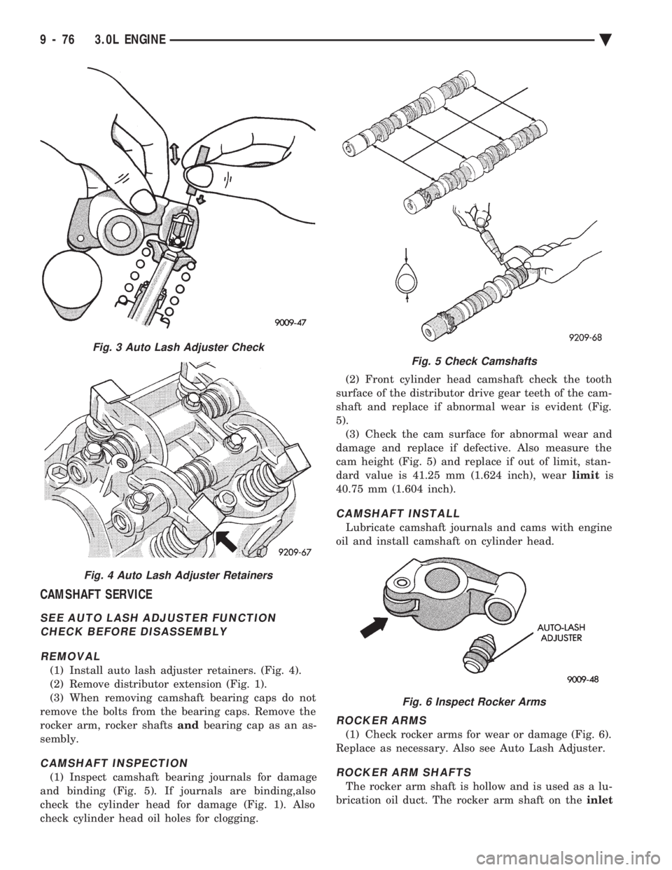
(1) Install auto lash adjuster retainers. (Fig. 4).
(2) Remove distributor extension (Fig. 1).
(3) When removing camshaft bearing caps do not
remove the bolts from the bearing caps. Remove the
rocker arm, rocker shafts andbearing cap as an as-
sembly.
CAMSHAFT INSPECTION
(1) Inspect camshaft bearing journals for damage
and binding (Fig. 5). If journals are binding,also
check the cylinder head for damage (Fig. 1). Also
check cylinder head oil holes for clogging. (2) Front cylinder head camshaft check the tooth
surface of the distributor drive gear teeth of the cam-
shaft and replace if abnormal wear is evident (Fig.
5). (3) Check the cam surface for abnormal wear and
damage and replace if defective. Also measure the
cam height (Fig. 5) and replace if out of limit, stan-
dard value is 41.25 mm (1.624 inch), wear limitis
40.75 mm (1.604 inch).
CAMSHAFT INSTALL
Lubricate camshaft journals and cams with engine
oil and install camshaft on cylinder head.
ROCKER ARMS
(1) Check rocker arms for wear or damage (Fig. 6).
Replace as necessary. Also see Auto Lash Adjuster.
ROCKER ARM SHAFTS
The rocker arm shaft is hollow and is used as a lu-
brication oil duct. The rocker arm shaft on the inlet
Fig. 3 Auto Lash Adjuster Check
Fig. 4 Auto Lash Adjuster Retainers
Fig. 5 Check Camshafts
Fig. 6 Inspect Rocker Arms
9 - 76 3.0L ENGINE Ä
Page 1643 of 2438
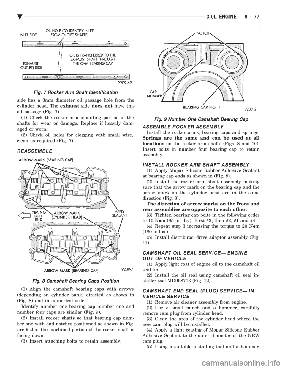
side has a 3mm diameter oil passage hole from the
cylinder head. The exhaustsidedoes not have this
oil passage (Fig. 7). (1) Check the rocker arm mounting portion of the
shafts for wear or damage. Replace if heavily dam-
aged or worn. (2) Check oil holes for clogging with small wire,
clean as required (Fig. 7).
REASSEMBLE
(1) Align the camshaft bearing caps with arrows
(depending on cylinder bank) directed as shown in
(Fig. 8) and in numerical order. Identify number one bearing cap number one and
number four caps are similar (Fig. 9). (2) Install rocker shafts so that bearing cap num-
ber one with end notches positioned as shown in Fig-
ure 9 that the machined portion of the rocker shaft is
facing down. (3) Insert attaching bolts to retain assembly.
ASSEMBLE ROCKER ASSEMBLY
Install the rocker arms, bearing caps and springs.
Springs are the same and can be used at all
locations on the rocker arm shafts (Figs. 8 and 10).
Insert bolts in number four bearing cap to retain
assembly.
INSTALL ROCKER ARM SHAFT ASSEMBLY
(1) Apply Mopar Silicone Rubber Adhesive Sealant
at bearing cap ends as shown in (Fig. 8). (2) Install the rocker arm shaft assembly making
sure that the arrow mark on the bearing cap and the
arrow mark on the cylinder head are in the same
direction (Fig. 8). The direction of arrow marks on the front and
rear assemblies are opposite to each other. (3) Tighten bearing cap bolts in the following order
to 10 N Im (85 in. lbs.). First #3, then #2, #1 and #4.
(4) Repeat step 3 increasing the torque to 20 N Im
(180 in.lbs.). (5) Install distributor drive adaptor assembly (Fig.
11).
CAMSHAFT OIL SEAL SERVICEÐ ENGINE OUT OF VEHICLE
(1) Apply light coat of engine oil to the camshaft oil
seal lip. (2) Install the oil seal using camshaft oil seal in-
staller tool MD998713 (Fig. 12).
CAMSHAFT END SEAL (PLUG) SERVICEÐ IN VEHICLE SERVICE
(1) Remove air cleaner assembly from engine.
(2) Use a small punch and a hammer, carefully
remove cam plug from cylinder head. (3) Clean the area of the cylinder head where the
new cam plug will be installed. (4) Apply a light coating of Mopar Silicone Rubber
Adhesive Sealant to the outer diameter of the NEW
cam plug. (5) Using a suitable installing tool and a hammer,
Fig. 7 Rocker Arm Shaft Identification
Fig. 8 Camshaft Bearing Caps Position
Fig. 9 Number One Camshaft Bearing Cap
Ä 3.0L ENGINE 9 - 77
Page 1644 of 2438
install the new cam plug to a depth of 0.5mm (0.020
inch) below the surface of the cylinder head. (6) Replace air cleaner assembly.
CAMSHAFT END SEAL (PLUG) SERVICE ÐOUT OF VEHICLE SERVICE
Install end seal plug with Special Tool MD998306.
(Fig. 13).CYLINDER HEAD
REMOVAL
(1) See Timing System this group for disassembly
and remove camshaft sprockets.
Fig. 10 Assemble Rocker Arm and Shafts
Fig. 11 Distributor Drive
Fig. 12 Install Camshaft Oil Seal
9 - 78 3.0L ENGINE Ä
Page 1645 of 2438
(2) See Camshaft Rocker Arms Removal.
(3) Remove upper intake manifold assembly. Refer
to Intake and Exhaust Manifolds, Group 11. (4) Remove distributor.
(5) Remove exhaust manifolds and cross over Refer
to Intake and Exhaust Manifolds, Group 11.
(6) Remove cylinder head bolts in sequence shown
in (Fig. 14) and remove cylinder head.
INSPECTION
(1) Before cleaning, check for leaks, damage and
cracks. (2) Clean cylinder head and oil passages.
(3) Check cylinder head for flatness (Fig. 15).
(4) Cylinder head must be flat within;
² Standard dimension = less than 0.05mm (.002
inch)
² Service Limit = 0.2mm (.008 inch)
² Grinding Limit = Maximum of 0.2 mm (.008 inch)
is permitted.
CAUTION: This is a combined total dimension of
stock removal from cylinder head if any and block
top surface.
Fig. 13 Install Camshaft End SealÐPlug
Fig. 14 Cylinder Head Bolt Removal Sequence
Fig. 15 Check Cylinder Head
Fig. 16 Cylinder Head Bolt Tightening Sequence
Ä 3.0L ENGINE 9 - 79
Page 1650 of 2438
PISTON RINGSÐINSTALLATION
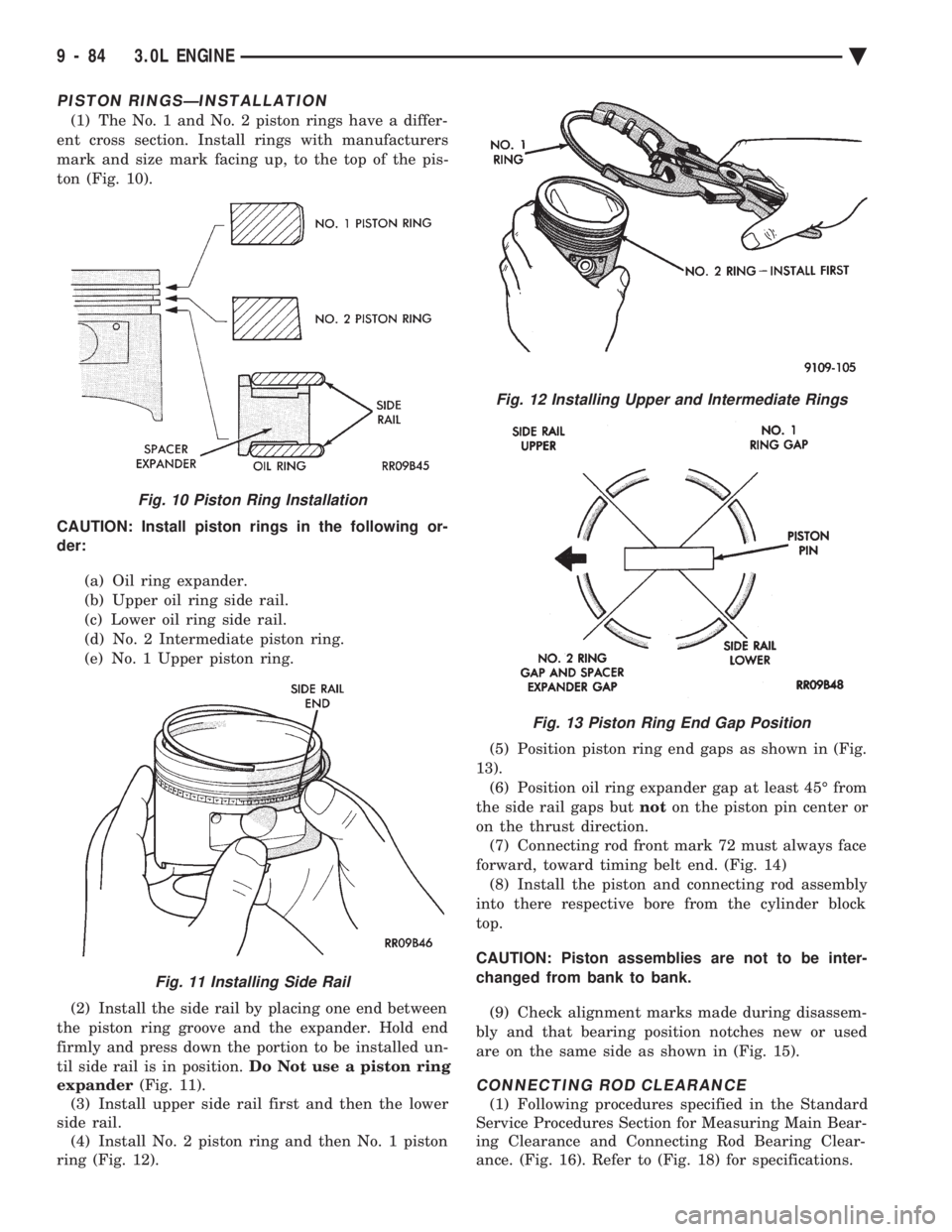
(1) The No. 1 and No. 2 piston rings have a differ-
ent cross section. Install rings with manufacturers
mark and size mark facing up, to the top of the pis-
ton (Fig. 10).
CAUTION: Install piston rings in the following or-
der:
(a) Oil ring expander.
(b) Upper oil ring side rail.
(c) Lower oil ring side rail.
(d) No. 2 Intermediate piston ring.
(e) No. 1 Upper piston ring.
(2) Install the side rail by placing one end between
the piston ring groove and the expander. Hold end
firmly and press down the portion to be installed un-
til side rail is in position. Do Not use a piston ring
expander (Fig. 11).
(3) Install upper side rail first and then the lower
side rail. (4) Install No. 2 piston ring and then No. 1 piston
ring (Fig. 12). (5) Position piston ring end gaps as shown in (Fig.
13). (6) Position oil ring expander gap at least 45É from
the side rail gaps but noton the piston pin center or
on the thrust direction. (7) Connecting rod front mark 72 must always face
forward, toward timing belt end. (Fig. 14) (8) Install the piston and connecting rod assembly
into there respective bore from the cylinder block
top.
CAUTION: Piston assemblies are not to be inter-
changed from bank to bank.
(9) Check alignment marks made during disassem-
bly and that bearing position notches new or used
are on the same side as shown in (Fig. 15).
CONNECTING ROD CLEARANCE
(1) Following procedures specified in the Standard
Service Procedures Section for Measuring Main Bear-
ing Clearance and Connecting Rod Bearing Clear-
ance. (Fig. 16). Refer to (Fig. 18) for specifications.
Fig. 10 Piston Ring Installation
Fig. 11 Installing Side Rail
Fig. 12 Installing Upper and Intermediate Rings
Fig. 13 Piston Ring End Gap Position
9 - 84 3.0L ENGINE Ä
Page 1652 of 2438
CRANKSHAFT AND CYLINDER BLOCK, ASSEMBLY SERVICE
CRANKSHAFT SERVICE
The crankshaft is supported in four main bearings.
All upper bearing shells in the crankcase have oil
grooves. All lower bearing shells in stalled in the
monoblock main bearing cap are plain. Crankshaft
end play is controlled by thrust washers on the num-
ber three main bearing journal.
CRANKSHAFTÐREMOVAL
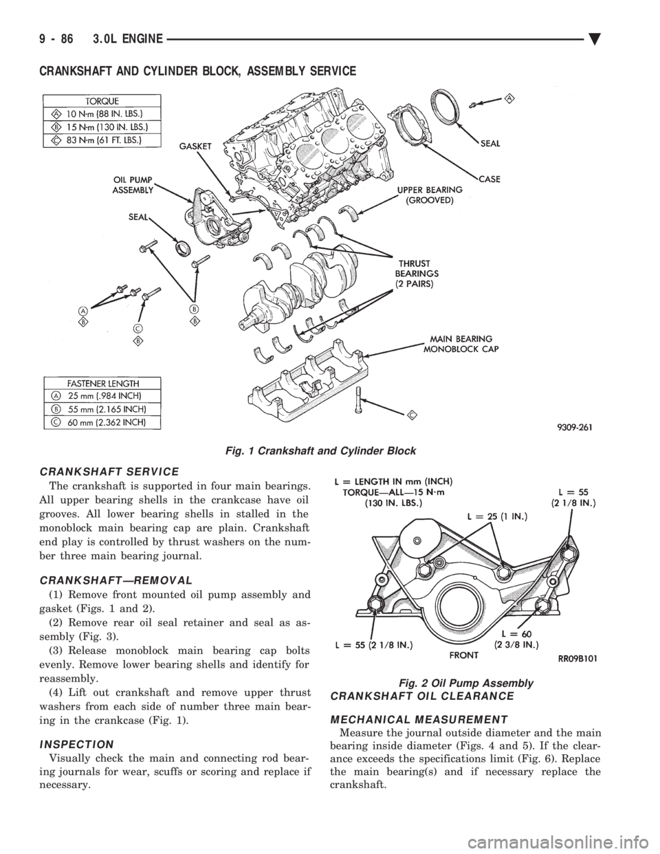
(1) Remove front mounted oil pump assembly and
gasket (Figs. 1 and 2). (2) Remove rear oil seal retainer and seal as as-
sembly (Fig. 3). (3) Release monoblock main bearing cap bolts
evenly. Remove lower bearing shells and identify for
reassembly. (4) Lift out crankshaft and remove upper thrust
washers from each side of number three main bear-
ing in the crankcase (Fig. 1).
INSPECTION
Visually check the main and connecting rod bear-
ing journals for wear, scuffs or scoring and replace if
necessary.
CRANKSHAFT OIL CLEARANCE
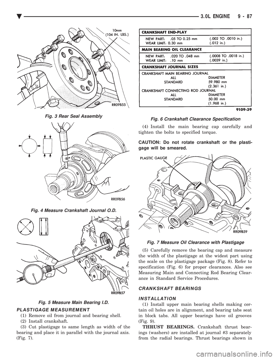
MECHANICAL MEASUREMENT
Measure the journal outside diameter and the main
bearing inside diameter (Figs. 4 and 5). If the clear-
ance exceeds the specifications limit (Fig. 6). Replace
the main bearing(s) and if necessary replace the
crankshaft.
Fig. 1 Crankshaft and Cylinder Block
Fig. 2 Oil Pump Assembly
9 - 86 3.0L ENGINE Ä
Page 1653 of 2438
PLASTIGAGE MEASUREMENT
(1) Remove oil from journal and bearing shell.
(2) Install crankshaft.
(3) Cut plastigage to same length as width of the
bearing and place it in parallel with the journal axis.
(Fig. 7). (4) Install the main bearing cap carefully and
tighten the bolts to specified torque.
CAUTION: Do not rotate crankshaft or the plasti-
gage will be smeared.
(5) Carefully remove the bearing cap and measure
the width of the plastigage at the widest part using
the scale on the plastigage package (Fig. 8). Refer to
specification (Fig. 6) for proper clearances. Also see
Measuring Main and Connecting Rod Bearing Clear-
ance in Standard Service Procedures.
CRANKSHAFT BEARINGS
INSTALLATION
(1) Install upper main bearing shells making cer-
tain oil holes are in alignment, and bearing tabs seat
in block tabs. All upper bearings have oil grooves
(Fig. 9). THRUST BEARINGS. Crankshaft thrust bear-
ings (washers) are installed at journal #3 separately
from the radial bearings. Thrust bearings shown in
Fig. 3 Rear Seal Assembly
Fig. 4 Measure Crankshaft Journal O.D.
Fig. 5 Measure Main Bearing I.D.
Fig. 6 Crankshaft Clearance Specification
Fig. 7 Measure Oil Clearance with Plastigage
Ä 3.0L ENGINE 9 - 87
Page 1654 of 2438
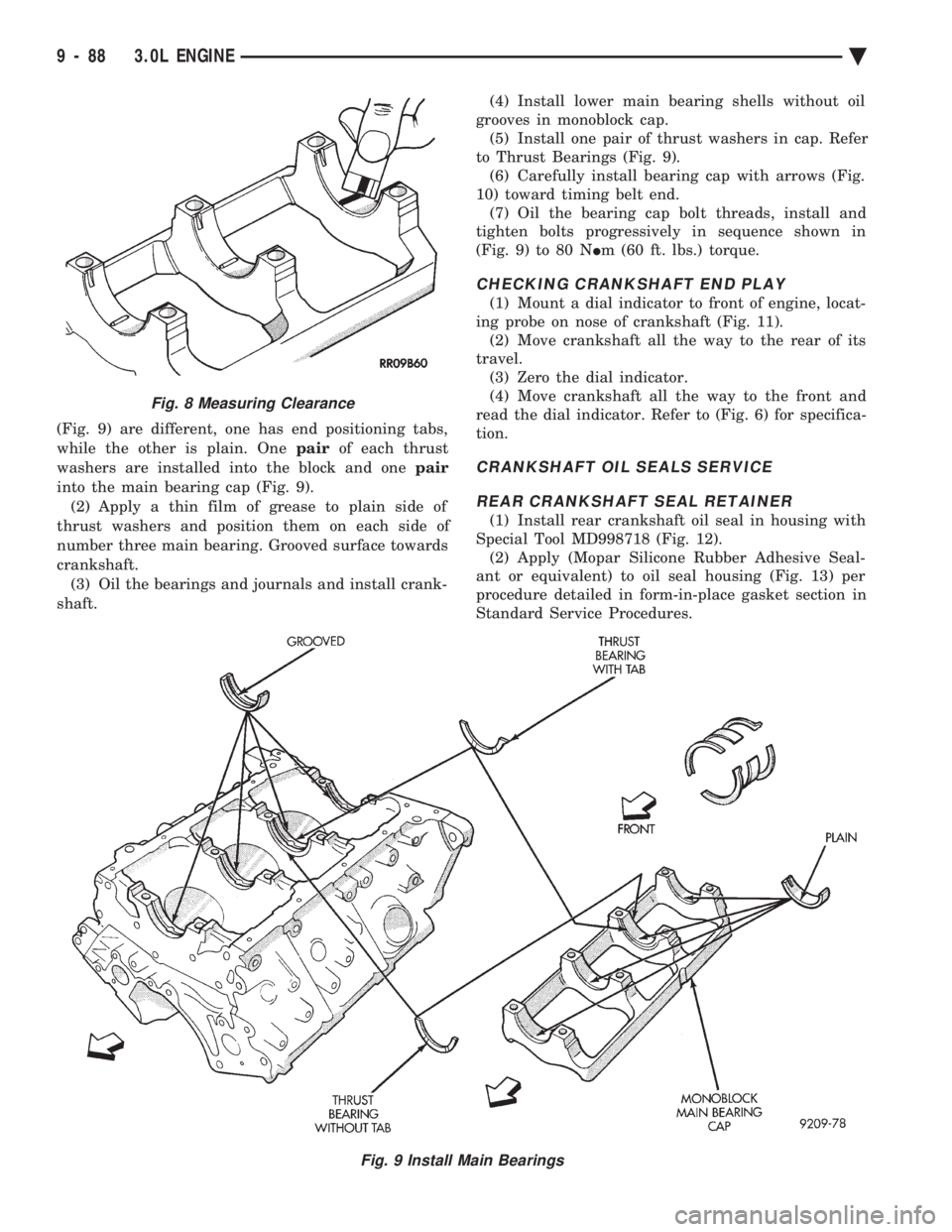
(Fig. 9) are different, one has end positioning tabs,
while the other is plain. One pairof each thrust
washers are installed into the block and one pair
into the main bearing cap (Fig. 9). (2) Apply a thin film of grease to plain side of
thrust washers and position them on each side of
number three main bearing. Grooved surface towards
crankshaft. (3) Oil the bearings and journals and install crank-
shaft. (4) Install lower main bearing shells without oil
grooves in monoblock cap. (5) Install one pair of thrust washers in cap. Refer
to Thrust Bearings (Fig. 9). (6) Carefully install bearing cap with arrows (Fig.
10) toward timing belt end. (7) Oil the bearing cap bolt threads, install and
tighten bolts progressively in sequence shown in
(Fig. 9) to 80 N Im (60 ft. lbs.) torque.
CHECKING CRANKSHAFT END PLAY
(1) Mount a dial indicator to front of engine, locat-
ing probe on nose of crankshaft (Fig. 11). (2) Move crankshaft all the way to the rear of its
travel. (3) Zero the dial indicator.
(4) Move crankshaft all the way to the front and
read the dial indicator. Refer to (Fig. 6) for specifica-
tion.
CRANKSHAFT OIL SEALS SERVICE
REAR CRANKSHAFT SEAL RETAINER
(1) Install rear crankshaft oil seal in housing with
Special Tool MD998718 (Fig. 12). (2) Apply (Mopar Silicone Rubber Adhesive Seal-
ant or equivalent) to oil seal housing (Fig. 13) per
procedure detailed in form-in-place gasket section in
Standard Service Procedures.
Fig. 9 Install Main Bearings
Fig. 8 Measuring Clearance
9 - 88 3.0L ENGINE Ä