1993 CHEVROLET DYNASTY oil
[x] Cancel search: oilPage 1579 of 2438
² Drive shaft distress: See Driveshafts in Suspension,
Group 2.
² Any front end structural damage (after repair).
² Insulator replacement.
ENGINE MOUNT INSULATOR ADJUSTMENT
(1) Remove the load on the engine motor mounts by
carefully supporting the engine and transmission as-
sembly with a floor jack. (2) Loosen the right engine mount insulator vertical
fasteners, and the front engine mount bracket to front
crossmember screws and nuts. Left engine mount insulator is sleeved over
shaft and long support bolt to provide lateral
movement adjustment with engine weight re-
moved or not. (3) Pry the engine right or left as required to achieve
the proper drive shaft assembly length. See Drive
Shaft in Suspension Group 2 for driveshaft identifica-
tion and related assembly length measuring. (4) Tighten right engine mount insulator vertical
bolts to 68 N Im (50 ft. lbs.). Then tighten front engine
mount screws and nuts to 54 N Im (40 ft. lbs.) and
center left engine mount insulator. (5) Recheck drive shaft length.
ENGINE ASSEMBLY
REMOVAL
(1) Disconnect battery.
(2) Scribe hood hinge outline on hood and remove
hood. (3) Drain cooling system.
(4) Remove hoses from radiator and engine.
(5) Remove radiator and fan assembly.
(6) Remove air cleaner and hoses.
(7) Remove air conditioning compressor mounting
bolts and set compressor aside, if equipped. (8) Remove power steering pump mounting bolts
and set pump aside (9) Remove oil filter.
(10) Disconnect fuel line, heater hose and acceler-
ator cable. (11) Disconnect all electrical connections and har-
nesses at throttle body and engine. (12) Manual Transmission
(a) Disconnect clutch cable.
(b) Remove transmission case lower cover.
(c) Disconnect exhaust pipe at manifold.
(d) Disconnect starter and lay aside.
(e) Install transmission holding fixture.
(13) Automatic Transmission
(a) Disconnect exhaust pipe at manifold.
(b) Disconnect starter and lay aside.
(c) Remove transmission case lower cover.
(d) Mark flex plate to torque converter.
(e) Remove screws holding torque converter to
flex plate.
(14) Attach C clamp on front bottom of torque con-
verter housing to prevent torque converter from com-
ing out. (15) Install transmission holding fixture.
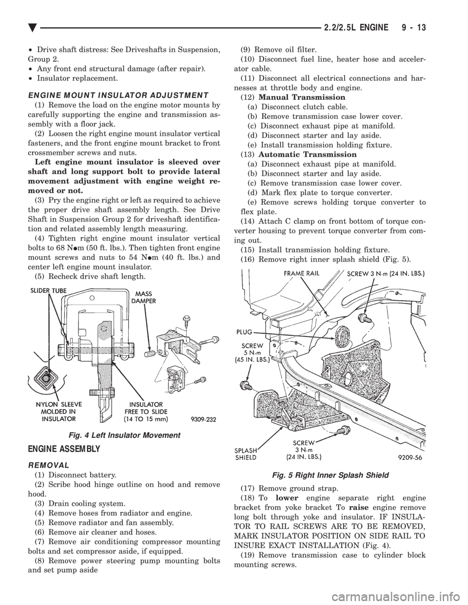
(16) Remove right inner splash shield (Fig. 5).
(17) Remove ground strap.
(18) To lowerengine separate right engine
bracket from yoke bracket To raiseengine remove
long bolt through yoke and insulator. IF INSULA-
TOR TO RAIL SCREWS ARE TO BE REMOVED,
MARK INSULATOR POSITION ON SIDE RAIL TO
INSURE EXACT INSTALLATION (Fig. 4). (19) Remove transmission case to cylinder block
mounting screws.Fig. 5 Right Inner Splash Shield
Fig. 4 Left Insulator Movement
Ä 2.2/2.5L ENGINE 9 - 13
Page 1580 of 2438
CAUTION: Make sure clutch cable has been discon-
nected. (20) Remove front engine mount screw and nut.
(21) Remove manual transmission damper.
(22) Remove left insulator through bolt from inside
wheelhouse or insulator bracket to transmission
screws. (23) Remove engine from vehicle.
INSTALLATION
(1) Install hoist to the engine and lower engine
into the engine compartment. SEE: ENGINE MOUNT RUBBER INSULATORS,
THIS GROUP. (2) Align engine mounts and install but do not
tighten until all mounting bolts have been installed.
(3) Install transmission case to cylinder block
mounting screws. Tighten to 95 N Im (70 ft. lbs.)
torque. (4) Remove engine hoist and transmission holding
fixture. (5) Install ground strap.
(6) Install right inner splash shield.
(7) Connect starter. See Electrical Group 8 for in-
stallation. (8) Connect exhaust system. See Exhaust Systems
Group 11 for installation. (9) Manual Transmission: Install transmission
case lower cover. Automatic Transmission: Remove C clamp from
torque converter housing. Align flexplate to torque
converter and install mounting screws. Tighten to 75
N Im (55 ft. lbs.) torque.
(10) Manual Transmission: Connect clutch cable.
See Clutch Group 6. (11) Install power steering pump. Refer to Cooling
System Group 7, Accessory Drive Section for belt
tension adjustment. (12) Connect fuel line, heater hose, and accelerator
cable. (13) Connect all electrical connections and har-
nesses at throttle body and engine. (14) Install oil filter. Fill engine crankcase with
proper oil to correct level. (15) Install air conditioning compressor (if
equipped). See Heater and Air Conditioning, Group
24 for installation. (16) Install air cleaner and hoses.
(17) Install radiator and shroud assembly . Install
radiator hoses. Fill cooling system. See Cooling Sys-
tem Group 7 for filling procedure. (18) Install hood.
(19) Connect battery.
(20) Start engine and run until operating temper-
ature is reached. (21) Adjust transmission linkage, if necessary.
SOLID MOUNT COMPRESSOR BRACKET SERVICE
When service procedures require solid mount
bracket removal and installation for example: cylin-
der head removal, etc., it is important that bracket
fasteners numbered 1 through 7 (Fig. 4) be removed
and installed in sequence, as instructed in Remove
and Install.
ACCESSORIES REMOVAL
(1) Remove (and install/adjust) belts,see Accessory
Drive Belts in Cooling System,Group 7. (2) Remove air conditioning compressor (in vehicle
with lines and set aside) (Fig. 6). (3) Remove generator pivot bolt and remove gener-
ator (in vehicle: turn wiring side up and disconnect,
then rotate generator, pulley end towards engine and
remove). (4) Remove air conditioner compressor belt idler.
SOLID MOUNT BRACKETÐREMOVAL (FIG. 4)
(1) Remove right engine mount yoke screw (see
Engine Remove Fig. 3) securing engine mount sup-
port strut to engine mount bracket. (2) Remove five side mounting bolts #1, #4 , #5,
#6, and #7 (Fig. 4). (3) Remove front mounting nut, #2, and remove
front bolt #3*. (4) Remove front mounting bolt and strut, rotate
solid mount bracket away from engine and slide
bracket on stud until #2 nut mounting stud until
free. Remove spacer from stud.
SOLID MOUNT BRACKETÐINSTALLATION
(1) Put spacer onto stud, then install bracket on
front (#2 nut) mounting stud and slide bracket over
timing belt cover into position. (2) Loosen assembly bracket to engine fasteners
(numbered #1 through #7 in Fig. 6). (3)
CAUTION: Fasteners MUST BE TIGHTENED IN SE-
QUENCE and to specified torque as follows :
² First Bolt #1 to 3.3 N Im (30 in. lbs.)
² Second Nut #2 and Bolt #3 to 54 N Im (40 ft. lbs.).
² Third Bolts #1 (second tightening) #4 and #5 to
54 N Im (40 ft. lbs.).
² Fourth Bolts #6 and #7 to 54 N Im (40 ft. lbs.).
(4) Install generator and compressor. Tighten com-
pressor mounting bracket bolts to 54 N Im (40 ft.
lbs.).
SOLID MOUNT COMPRESSOR BRACKET SERVICEÐTURBO III ENGINE
REMOVAL
(1) Disconnect negative battery cable
9 - 14 2.2/2.5L ENGINE Ä
Page 1585 of 2438
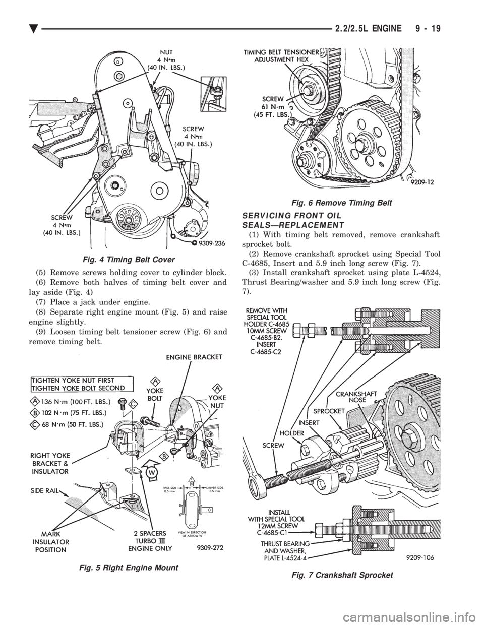
(5) Remove screws holding cover to cylinder block.
(6) Remove both halves of timing belt cover and
lay aside (Fig. 4) (7) Place a jack under engine.
(8) Separate right engine mount (Fig. 5) and raise
engine slightly. (9) Loosen timing belt tensioner screw (Fig. 6) and
remove timing belt.
SERVICING FRONT OIL SEALSÐREPLACEMENT
(1) With timing belt removed, remove crankshaft
sprocket bolt. (2) Remove crankshaft sprocket using Special Tool
C-4685, Insert and 5.9 inch long screw (Fig. 7). (3) Install crankshaft sprocket using plate L-4524,
Thrust Bearing/washer and 5.9 inch long screw (Fig.
7).
Fig. 4 Timing Belt Cover
Fig. 7 Crankshaft SprocketFig. 5 Right Engine Mount
Fig. 6 Remove Timing Belt
Ä 2.2/2.5L ENGINE 9 - 19
Page 1586 of 2438
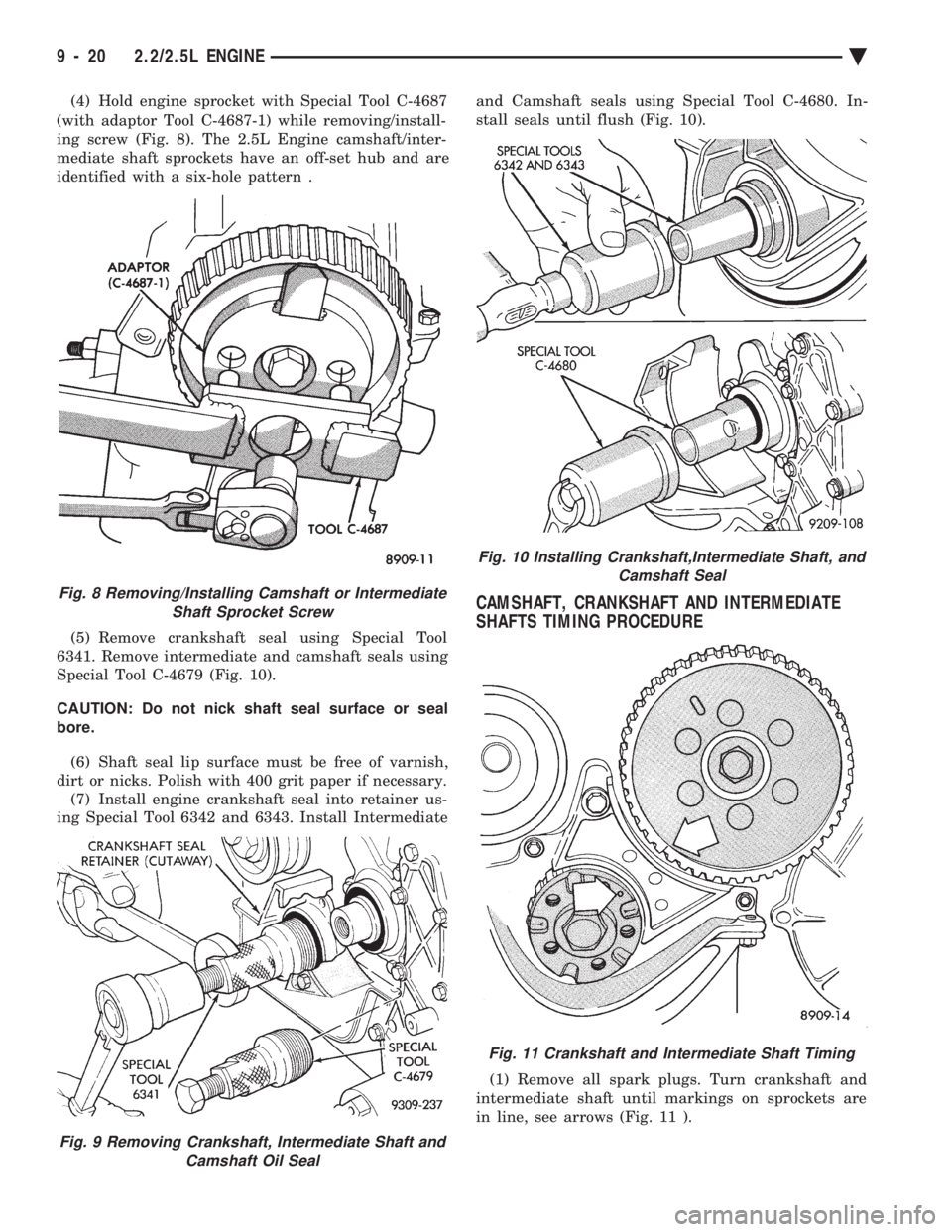
(4) Hold engine sprocket with Special Tool C-4687
(with adaptor Tool C-4687-1) while removing/install-
ing screw (Fig. 8). The 2.5L Engine camshaft/inter-
mediate shaft sprockets have an off-set hub and are
identified with a six-hole pattern .
(5) Remove crankshaft seal using Special Tool
6341. Remove intermediate and camshaft seals using
Special Tool C-4679 (Fig. 10).
CAUTION: Do not nick shaft seal surface or seal
bore.
(6) Shaft seal lip surface must be free of varnish,
dirt or nicks. Polish with 400 grit paper if necessary. (7) Install engine crankshaft seal into retainer us-
ing Special Tool 6342 and 6343. Install Intermediate and Camshaft seals using Special Tool C-4680. In-
stall seals until flush (Fig. 10).
CAMSHAFT, CRANKSHAFT AND INTERMEDIATE
SHAFTS TIMING PROCEDURE
(1) Remove all spark plugs. Turn crankshaft and
intermediate shaft until markings on sprockets are
in line, see arrows (Fig. 11 ).
Fig. 9 Removing Crankshaft, Intermediate Shaft and Camshaft Oil Seal
Fig. 8 Removing/Installing Camshaft or IntermediateShaft Sprocket Screw
Fig. 10 Installing Crankshaft,Intermediate Shaft, and Camshaft Seal
Fig. 11 Crankshaft and Intermediate Shaft Timing
9 - 20 2.2/2.5L ENGINE Ä
Page 1587 of 2438
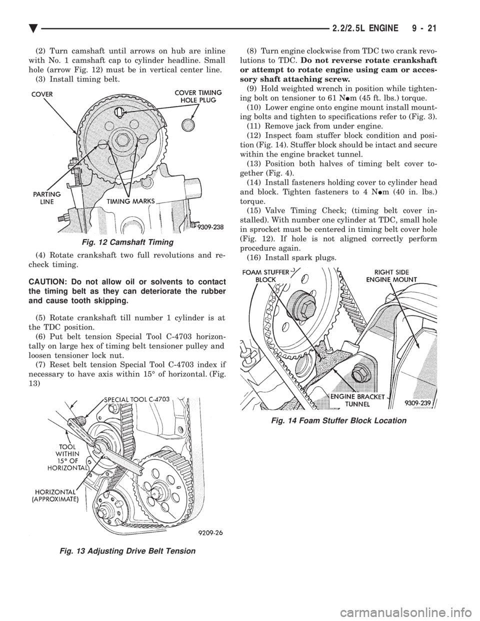
(2) Turn camshaft until arrows on hub are inline
with No. 1 camshaft cap to cylinder headline. Small
hole (arrow Fig. 12) must be in vertical center line. (3) Install timing belt.
(4) Rotate crankshaft two full revolutions and re-
check timing.
CAUTION: Do not allow oil or solvents to contact
the timing belt as they can deteriorate the rubber
and cause tooth skipping.
(5) Rotate crankshaft till number 1 cylinder is at
the TDC position. (6) Put belt tension Special Tool C-4703 horizon-
tally on large hex of timing belt tensioner pulley and
loosen tensioner lock nut. (7) Reset belt tension Special Tool C-4703 index if
necessary to have axis within 15É of horizontal. (Fig.
13) (8) Turn engine clockwise from TDC two crank revo-
lutions to TDC. Do not reverse rotate crankshaft
or attempt to rotate engine using cam or acces-
sory shaft attaching screw. (9) Hold weighted wrench in position while tighten-
ing bolt on tensioner to 61 N Im (45 ft. lbs.) torque.
(10) Lower engine onto engine mount install mount-
ing bolts and tighten to specifications refer to (Fig. 3). (11) Remove jack from under engine.
(12) Inspect foam stuffer block condition and posi-
tion (Fig. 14). Stuffer block should be intact and secure
within the engine bracket tunnel. (13) Position both halves of timing belt cover to-
gether (Fig. 4). (14) Install fasteners holding cover to cylinder head
and block. Tighten fasteners to 4 N Im (40 in. lbs.)
torque. (15) Valve Timing Check; (timing belt cover in-
stalled). With number one cylinder at TDC, small hole
in sprocket must be centered in timing belt cover hole
(Fig. 12). If hole is not aligned correctly perform
procedure again. (16) Install spark plugs.
Fig. 12 Camshaft Timing
Fig. 13 Adjusting Drive Belt Tension
Fig. 14 Foam Stuffer Block Location
Ä 2.2/2.5L ENGINE 9 - 21
Page 1589 of 2438
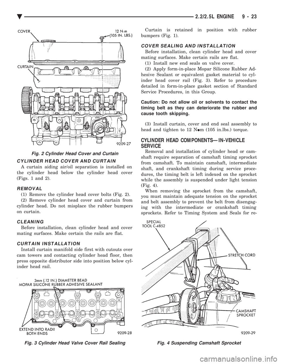
CYLINDER HEAD COVER AND CURTAIN
A curtain aiding air/oil separation is installed on
the cylinder head below the cylinder head cover
(Figs. 1 and 2).
REMOVAL
(1) Remove the cylinder head cover bolts (Fig. 2).
(2) Remove cylinder head cover and curtain from
cylinder head. Do not misplace the rubber bumpers
on curtain.
CLEANING
Before installation, clean cylinder head and cover
mating surfaces. Make certain the rails are flat.
CURTAIN INSTALLATION
Install curtain manifold side first with cutouts over
cam towers and contacting cylinder head floor, then
press opposite distributor side into position below cyl-
inder head rail. Curtain is retained in position with rubber
bumpers (Fig. 1).
COVER SEALING AND INSTALLATION
Before installation, clean cylinder head and cover
mating surfaces. Make certain rails are flat. (1) Install new end seals on valve cover.
(2) Apply form-in-place Mopar Silicone Rubber Ad-
hesive Sealant or equivalent gasket material to cyl-
inder head cover rail (Fig. 3). Refer to procedure
detailed in form-in-place gasket section of Standard
Service Procedures, in this Group.
Caution: Do not allow oil or solvents to contact the
timing belt as they can deteriorate the rubber and
cause tooth skipping.
(3) Install curtain, cover and end seal assembly to
head and tighten to 12 N Im (105 in.lbs.) torque.
CYLINDER HEAD COMPONENTSÐIN-VEHICLE
SERVICE
Removal and installation of cylinder head or cam-
shaft require separation of camshaft timing sprocket
from camshaft. To maintain camshaft, intermediate
shaft, and crankshaft timing during service proce-
dures, the timing belt is left indexed on the sprocket
while the assembly is suspended under light tension
(Fig. 4). When removing the sprocket from the camshaft,
you must maintain adequate tension on the sprocket
and belt assembly to prevent the belt from disengag-
ing with the intermediate or crankshaft timing
sprockets. Refer to Timing System and Seals for re-Fig. 2 Cylinder Head Cover and Curtain
Fig. 3 Cylinder Head Valve Cover Rail SealingFig. 4 Suspending Camshaft Sprocket
Ä 2.2/2.5L ENGINE 9 - 23
Page 1590 of 2438
moval and installation of camshaft sprocket proce-
dure and to Camshaft Service for removal and
installation of camshaft procedures.
CAUTION: Failure to maintain adequate tension on
camshaft, intermediate, and crankshaft sprocket
belt can result in lost engine timing. If timing is
lost, refer to Timing System and Seals and (Fig. 4).
CAMSHAFT SERVICE
Refer to TIMING SYSTEM AND SEALS for cam- shaft timing belt and sprocket removal and installa-
tion, and CYLINDER HEAD In Vehicle Service.
REMOVAL
(1) Remove the cylinder head cover and curtain.
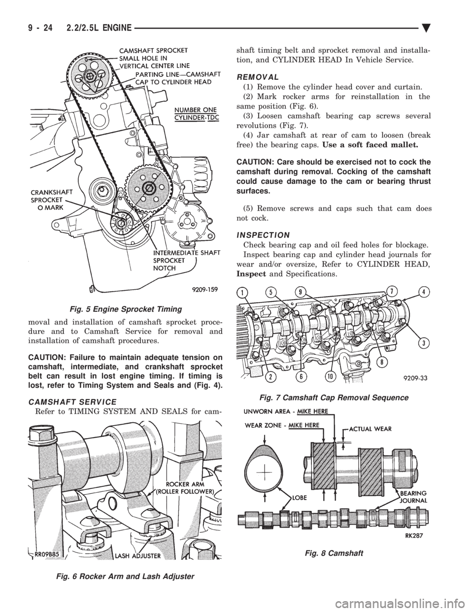
(2) Mark rocker arms for reinstallation in the
same position (Fig. 6). (3) Loosen camshaft bearing cap screws several
revolutions (Fig. 7). (4) Jar camshaft at rear of cam to loosen (break
free) the bearing caps. Use a soft faced mallet.
CAUTION: Care should be exercised not to cock the
camshaft during removal. Cocking of the camshaft
could cause damage to the cam or bearing thrust
surfaces.
(5) Remove screws and caps such that cam does
not cock.
INSPECTION
Check bearing cap and oil feed holes for blockage.
Inspect bearing cap and cylinder head journals for
wear and/or oversize, Refer to CYLINDER HEAD,
Inspect and Specifications.
Fig. 5 Engine Sprocket Timing
Fig. 6 Rocker Arm and Lash Adjuster
Fig. 7 Camshaft Cap Removal Sequence
Fig. 8 Camshaft
9 - 24 2.2/2.5L ENGINE Ä
Page 1591 of 2438
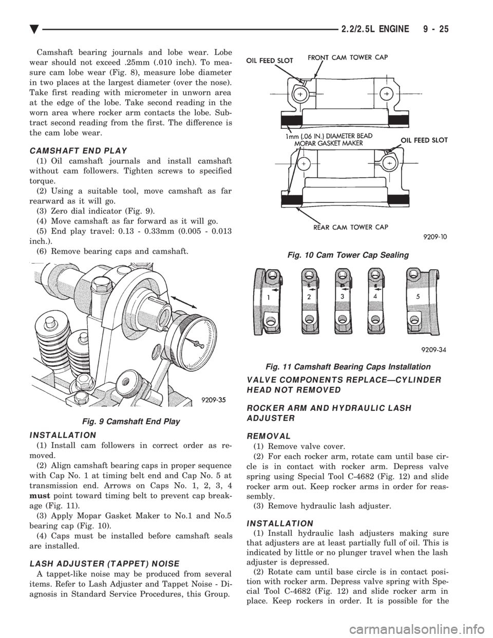
Camshaft bearing journals and lobe wear. Lobe
wear should not exceed .25mm (.010 inch). To mea-
sure cam lobe wear (Fig. 8), measure lobe diameter
in two places at the largest diameter (over the nose).
Take first reading with micrometer in unworn area
at the edge of the lobe. Take second reading in the
worn area where rocker arm contacts the lobe. Sub-
tract second reading from the first. The difference is
the cam lobe wear.
CAMSHAFT END PLAY
(1) Oil camshaft journals and install camshaft
without cam followers. Tighten screws to specified
torque. (2) Using a suitable tool, move camshaft as far
rearward as it will go. (3) Zero dial indicator (Fig. 9).
(4) Move camshaft as far forward as it will go.
(5) End play travel: 0.13 - 0.33mm (0.005 - 0.013
inch.). (6) Remove bearing caps and camshaft.
INSTALLATION
(1) Install cam followers in correct order as re-
moved. (2) Align camshaft bearing caps in proper sequence
with Cap No. 1 at timing belt end and Cap No. 5 at
transmission end. Arrows on Caps No. 1, 2, 3, 4
must point toward timing belt to prevent cap break-
age (Fig. 11). (3) Apply Mopar Gasket Maker to No.1 and No.5
bearing cap (Fig. 10). (4) Caps must be installed before camshaft seals
are installed.
LASH ADJUSTER (TAPPET) NOISE
A tappet-like noise may be produced from several
items. Refer to Lash Adjuster and Tappet Noise - Di-
agnosis in Standard Service Procedures, this Group.
VALVE COMPONENTS REPLACEÐCYLINDER HEAD NOT REMOVED
ROCKER ARM AND HYDRAULIC LASH ADJUSTER
REMOVAL
(1) Remove valve cover.
(2) For each rocker arm, rotate cam until base cir-
cle is in contact with rocker arm. Depress valve
spring using Special Tool C-4682 (Fig. 12) and slide
rocker arm out. Keep rocker arms in order for reas-
sembly. (3) Remove hydraulic lash adjuster.
INSTALLATION
(1) Install hydraulic lash adjusters making sure
that adjusters are at least partially full of oil. This is
indicated by little or no plunger travel when the lash
adjuster is depressed. (2) Rotate cam until base circle is in contact posi-
tion with rocker arm. Depress valve spring with Spe-
cial Tool C-4682 (Fig. 12) and slide rocker arm in
place. Keep rockers in order. It is possible for the
Fig. 9 Camshaft End Play
Fig. 10 Cam Tower Cap Sealing
Fig. 11 Camshaft Bearing Caps Installation
Ä 2.2/2.5L ENGINE 9 - 25