1993 CHEVROLET DYNASTY service
[x] Cancel search: servicePage 184 of 2438
SERVICE PRECAUTIONS
WARNING: DUST AND DIRT ON BRAKE PARTS
GENERATED DURING THE NORMAL USE AND
WEAR OF MOTOR VEHICLE BRAKE SYSTEMS CAN
CONTAIN ASBESTOS FIBERS. BREATHING EXCES-
SIVE CONCENTRATIONS OF ASBESTOS FIBERS
CAN CAUSE SERIOUS BODILY HARM, SUCH AS
ASBESTOSIS AND CANCER. EXTREME CARE
SHOULD BE EXERCISED WHILE SERVICING
BRAKE ASSEMBLIES OR COMPONENTS. DO NOT CLEAN BRAKE ASSEMBLIES OR COM-
PONENTS WITH COMPRESSED AIR OR BY DRY
BRUSHING; USE A VACUUM CLEANER SPECIFI-
CALLY RECOMMENDED FOR USE WITH ASBES-
TOS FIBERS. IF A SUITABLE VACUUM CLEANER IS
NOT AVAILABLE, CLEANING SHOULD BE DONE
WET USING A WATER DAMPENED CLOTH. DO NOT CREATE DUST BY SANDING, GRINDING,
AND/OR SHAVING BRAKE LININGS OR PADS UN-
LESS SUCH OPERATION IS DONE WHILE USING
PROPERLY EXHAUST VENTILATED EQUIPMENT. DISPOSE OF ALL DUST AND DIRT SUSPECTED
TO CONTAIN ANY ASBESTOS FIBERS IN SEALED
BAGS OR CONTAINERS TO MINIMIZE DUST EXPO-
SURE TO YOURSELF AND OTHERS. FOLLOW ALL RECOMMENDED PRACTICES PRE-
SCRIBED BY THE OCCUPATIONAL SAFETY AND
HEALTH ADMINISTRATION AND THE ENVIRONMEN-
TAL PROTECTION AGENCY. FOR THE HANDLING,
PROCESSING, AND DISPOSITION OF DUST OR DIRT
WHICH MAY CONTAIN ASBESTOS FIBERS. IT IS RECOMMENDED NOT TO BREATH ANY TYPE
OF BRAKE LINING MATERIAL DUST EVEN ASBES-
TOS FREE, DUE TO THE FIBROUS NATURE OF THE
MATERIALS BEING USED.
Grease or any other foreign material must be kept off
caliper assembly, surfaces of braking disc and external
surfaces of hub, during service procedures. Handling of the braking disc and caliper. Should be
done in such a way as to avoid deformation of the disc
and scratching or nicking of the brake linings. If inspection reveals that the square sectioned cali-
per piston seal is worn or damaged, it should be
replaced immediately. During removal and installation of a wheel and tire
assembly, use care not to strike the caliper. Before vehicle is moved after any brake service
work, be sure to obtain a firm brake pedal.
5 - 34 BRAKES Ä
Page 185 of 2438
KELSEY HAYES DOUBLE PIN FAMILY CALIPER
BRAKE SHOE SERVICE PROCEDURES
BRAKE SHOE REMOVAL
(1) Raise vehicle on jackstands or centered on a
hoist. See Hoisting Information in the Lubrication
and Maintenance section of this manual. (2) Remove front wheel and tire assemblies.
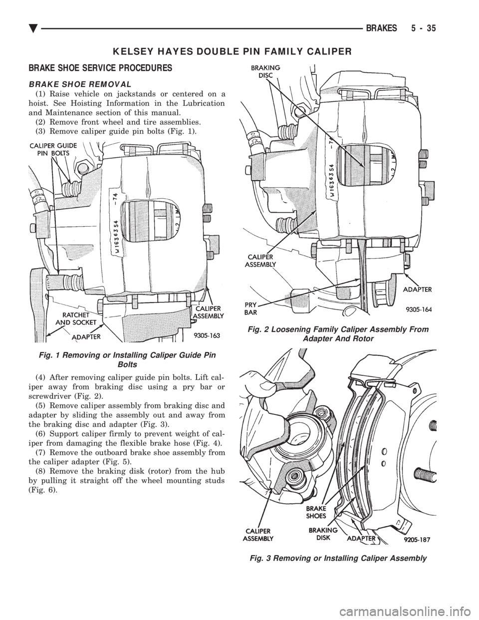
(3) Remove caliper guide pin bolts (Fig. 1).
(4) After removing caliper guide pin bolts. Lift cal-
iper away from braking disc using a pry bar or
screwdriver (Fig. 2). (5) Remove caliper assembly from braking disc and
adapter by sliding the assembly out and away from
the braking disc and adapter (Fig. 3). (6) Support caliper firmly to prevent weight of cal-
iper from damaging the flexible brake hose (Fig. 4). (7) Remove the outboard brake shoe assembly from
the caliper adapter (Fig. 5). (8) Remove the braking disk (rotor) from the hub
by pulling it straight off the wheel mounting studs
(Fig. 6).
Fig. 1 Removing or Installing Caliper Guide Pin Bolts
Fig. 2 Loosening Family Caliper Assembly FromAdapter And Rotor
Fig. 3 Removing or Installing Caliper Assembly
Ä BRAKES 5 - 35
Page 188 of 2438
KELSEY HAYES DOUBLE PIN NON-FAMILY CALIPER INDEX
page page
Assembling Disc Brake Caliper .............. 42
Cleaning and Inspection of Brake Caliper ...... 41 Disc Brake Caliper Disassembly
............. 40
Service Procedures ....................... 38
SERVICE PROCEDURES
BRAKE SHOES REMOVE
(1) Raise the vehicle on jackstands or centered on
a hoist. (2) Remove the front wheel and tire assemblies
from the vehicle. (3) Remove the brake caliper assembly to steering
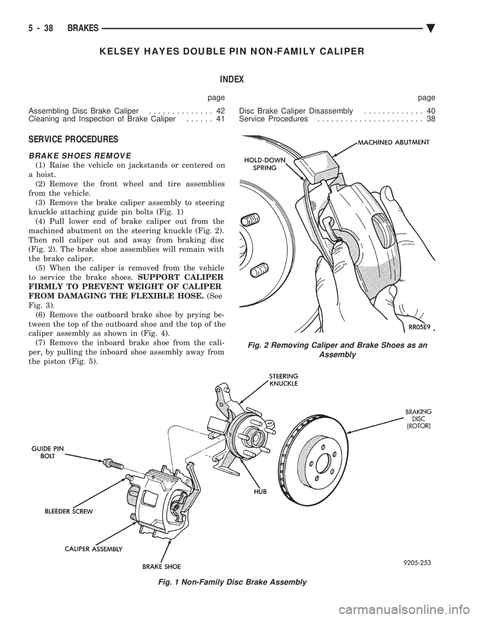
knuckle attaching guide pin bolts (Fig. 1) (4) Pull lower end of brake caliper out from the
machined abutment on the steering knuckle (Fig. 2).
Then roll caliper out and away from braking disc
(Fig. 2). The brake shoe assemblies will remain with
the brake caliper. (5) When the caliper is removed from the vehicle
to service the brake shoes. SUPPORT CALIPER
FIRMLY TO PREVENT WEIGHT OF CALIPER
FROM DAMAGING THE FLEXIBLE HOSE. (See
Fig. 3). (6) Remove the outboard brake shoe by prying be-
tween the top of the outboard shoe and the top of the
caliper assembly as shown in (Fig. 4). (7) Remove the inboard brake shoe from the cali-
per, by pulling the inboard shoe assembly away from
the piston (Fig. 5).
Fig. 1 Non-Family Disc Brake Assembly
Fig. 2 Removing Caliper and Brake Shoes as an Assembly
5 - 38 BRAKES Ä
Page 191 of 2438
(5) Clamp caliper in vise (with protective caps on
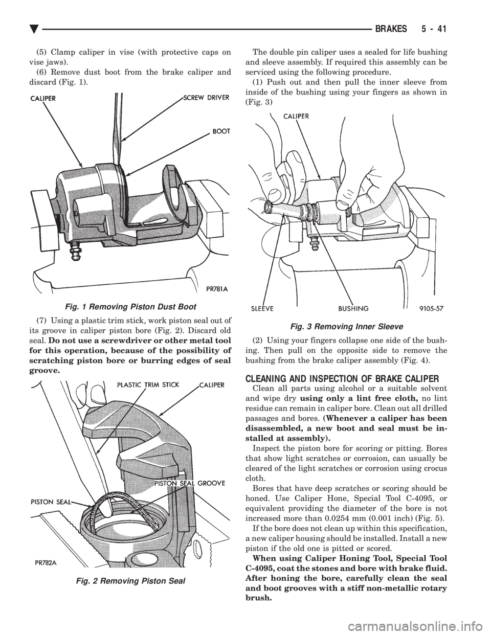
vise jaws). (6) Remove dust boot from the brake caliper and
discard (Fig. 1).
(7) Using a plastic trim stick, work piston seal out of
its groove in caliper piston bore (Fig. 2). Discard old
seal. Do not use a screwdriver or other metal tool
for this operation, because of the possibility of
scratching piston bore or burring edges of seal
groove. The double pin caliper uses a sealed for life bushing
and sleeve assembly. If required this assembly can be
serviced using the following procedure. (1) Push out and then pull the inner sleeve from
inside of the bushing using your fingers as shown in
(Fig. 3)
(2) Using your fingers collapse one side of the bush-
ing. Then pull on the opposite side to remove the
bushing from the brake caliper assembly (Fig. 4).
CLEANING AND INSPECTION OF BRAKE CALIPER
Clean all parts using alcohol or a suitable solvent
and wipe dry using only a lint free cloth, no lint
residue can remain in caliper bore. Clean out all drilled
passages and bores. (Whenever a caliper has been
disassembled, a new boot and seal must be in-
stalled at assembly). Inspect the piston bore for scoring or pitting. Bores
that show light scratches or corrosion, can usually be
cleared of the light scratches or corrosion using crocus
cloth. Bores that have deep scratches or scoring should be
honed. Use Caliper Hone, Special Tool C-4095, or
equivalent providing the diameter of the bore is not
increased more than 0.0254 mm (0.001 inch) (Fig. 5). If the bore does not clean up within this specification,
a new caliper housing should be installed. Install a new
piston if the old one is pitted or scored. When using Caliper Honing Tool, Special Tool
C-4095, coat the stones and bore with brake fluid.
After honing the bore, carefully clean the seal
and boot grooves with a stiff non-metallic rotary
brush.
Fig. 1 Removing Piston Dust Boot
Fig. 2 Removing Piston Seal
Fig. 3 Removing Inner Sleeve
Ä BRAKES 5 - 41
Page 195 of 2438
REAR DISC BRAKES INDEX
page page
Assembling Rear Disc Brake Caliper .......... 49
Brake Shoe Removal ..................... 46
Cleaning and Inspection ................... 49
Disassembling Rear Caliper Assembly ......... 48 General Information
....................... 45
Lining Wear ............................. 45
Service Precautions ....................... 46
GENERAL INFORMATION
The rear disc brakes are similar to front disc
brakes, however, there are several distinctive fea-
tures that require different service procedures. This
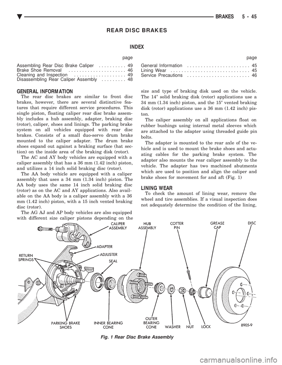
single piston, floating caliper rear disc brake assem-
bly includes a hub assembly, adapter, braking disc
(rotor), caliper, shoes and linings. The parking brake
system on all vehicles equipped with rear disc
brakes. Consists of a small duo-servo drum brake
mounted to the caliper adapter. The drum brake
shoes expand out against a braking surface (hat sec-
tion) on the inside area of the braking disk (rotor). The AC and AY body vehicles are equipped with a
caliper assembly that has a 36 mm (1.42 inch) piston,
and utilizes a 14 inch solid braking disc (rotor). The AA body vehicle are equipped with a caliper
assembly that uses a 34 mm (1.34 inch) piston. The
AA body uses the same 14 inch solid braking disc
(rotor) as on the AC and AY applications. Also avail-
able on the AA body is a caliper assembly with a 36
mm (1.42 inch) piston, with a 15 inch vented braking
disc (rotor). The AG AJ and AP body vehicles are also equipped
with different size caliper pistons depending on the size and type of braking disk used on the vehicle.
The 14 9solid braking disk (rotor) applications use a
34 mm (1.34 inch) piston, and the 15 9vented braking
disk (rotor) applications use a 36 mm (1.42 inch) pis-
ton. The caliper assembly on all applications float on
rubber bushings using internal metal sleeves which
are attached to the adapter using threaded guide pin
bolts. The adapter is mounted to the rear axle of the ve-
hicle and is used to mount the brake shoes and actu-
ating cables for the parking brake system. The
adapter also mounts the rear caliper assembly to the
vehicle. The adapter has two machined abutments
which are used to position and align the caliper and
brake shoes for movement for and aft (Fig. 1)
LINING WEAR
To check the amount of lining wear, remove the
wheel and tire assemblies. If a visual inspection does
not adequately determine the condition of the lining,
Fig. 1 Rear Disc Brake Assembly
Ä BRAKES 5 - 45
Page 196 of 2438
removal will be necessary. Remove the shoe and lin-
ing assemblies (see Brake Shoe Removal).Combined shoe and lining thickness should be
measured at the thinnest part of the assembly. When a shoe and lining assembly is worn to a
thickness of approximately 7.0 mm (9/32 inch) it
should be replaced. Replace both shoe assemblies (inboard and out-
board) on both wheels whenever shoe assemblies on
either side are replaced. If a shoe assembly does not require replacement.
Reinstall it, making sure each shoe assembly is re-
turned to its original position on the wheel of the ve-
hicle from which it was removed. (See Brake Shoe
Installation).
SERVICE PRECAUTIONS
WARNING: DUST AND DIRT ON BRAKE PARTS
GENERATED DURING THE NORMAL USE AND
WEAR OF MOTOR VEHICLE BRAKE SYSTEMS CAN
CONTAIN ASBESTOS FIBERS. BREATHING EXCES-
SIVE CONCENTRATIONS OF ASBESTOS FIBERS
CAN CAUSE SERIOUS BODILY HARM, SUCH AS
ASBESTOSIS AND CANCER. EXTREME CARE
SHOULD BE EXERCISED WHILE SERVICING
BRAKE ASSEMBLIES OR COMPONENTS. DO NOT CLEAN BRAKE ASSEMBLIES OR COM-
PONENTS WITH COMPRESSED AIR OR BY DRY
BRUSHING; USE A VACUUM CLEANER SPECIFI-
CALLY RECOMMENDED FOR USE WITH ASBES-
TOS FIBERS. IF A SUITABLE VACUUM CLEANER IS
NOT AVAILABLE, CLEANING SHOULD BE DONE
WET USING A WATER DAMPENED CLOTH. DO NOT CREATE DUST BY SANDING, GRINDIN-
G,AND/OR SHAVING BRAKE LININGS OR PADS
UNLESS SUCH OPERATION IS DONE WHILE USING
PROPERLY EXHAUST VENTILATED EQUIPMENT. DISPOSE OF ALL DUST AND DIRT SUSPECTED
TO CONTAIN ANY ASBESTOS FIBERS IN SEALED
BAGS OR CONTAINERS TO MINIMIZE DUST EXPO-
SURE TO YOURSELF AND OTHERS. FOLLOW ALL RECOMMENDED PRACTICES PRE-
SCRIBED BY THE OCCUPATIONAL SAFETY AND
HEALTH ADMINISTRATION AND THE ENVIRON-
MENTAL PROTECTION AGENCY. FOR THE HAN-
DLING, PROCESSING, AND DISPOSITION OF DUST
OR DIRT WHICH MAY CONTAIN ASBESTOS FI-
BERS. IT IS RECOMMENDED NOT TO BREATH ANY
TYPE OF BRAKE LINING MATERIAL DUST EVEN
ASBESTOS FREE, DUE TO THE FIBROUS NATURE
OF THE MATERIALS BEING USED.
Grease or any other foreign material must be kept
off the caliper assembly, surfaces of the braking disc
and external surfaces of the hub, during service pro-
cedures. Handling the braking disc and caliper should be done
in such a way as to avoid deformation of the disc and
scratching or nicking the brake linings (pads). During removal and installation of a wheel and tire
assembly, use care not to strike the caliper. Before vehicle is moved after any brake service
work, be sure to obtain a firm brake pedal.
BRAKE SHOE REMOVAL
(1) Raise vehicle on jackstands or centered on a
hoist. (2) Remove rear wheel and tire assemblies.
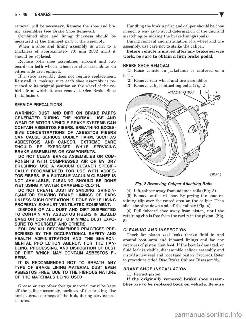
(3) Remove caliper attaching bolts (Fig. 2).
(4) Lift caliper away from adapter rails (Fig. 3).
(5) Remove outboard shoe. By prying the shoe re-
taining clip over the raised area on the caliper. Then
slide the shoe down and off the caliper (Fig. 4). (6) Pull inboard shoe away from piston, until the
retaining clip is free from the cavity in the piston. (Fig.
5).
CLEANING AND INSPECTION
Check for piston seal leaks (brake fluid in and
around boot area and inboard lining) and for any
ruptures of piston dust boot. If the boot is damaged, or
fluid leak is visible, disassemble caliper assembly and
install a new seal and boot (and piston if scored). Refer
to procedure titled Disc Brake Caliper Disassembly.
BRAKE SHOE INSTALLATION
(1) Retract piston.
If the originally removed brake shoe assem-
blies are to be replaced back on vehicle. Be sure
Fig. 2 Removing Caliper Attaching Bolts
5 - 46 BRAKES Ä
Page 199 of 2438
tool for this operation, because of the possibility
of scratching piston bore or burring edges of seal
groove. The double pin caliper uses a sealed for life bushing
and sleeve assembly. If required this assembly can be
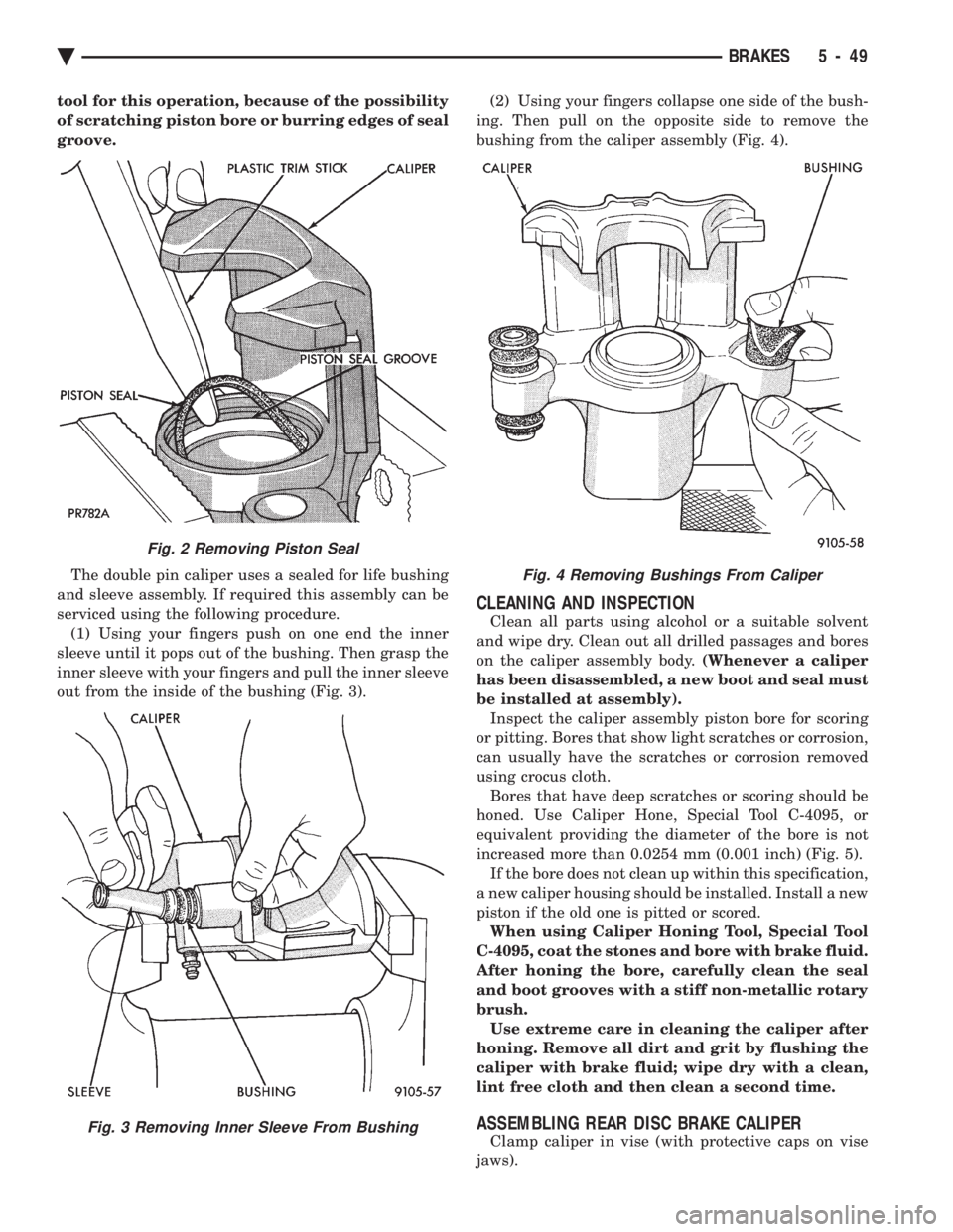
serviced using the following procedure. (1) Using your fingers push on one end the inner
sleeve until it pops out of the bushing. Then grasp the
inner sleeve with your fingers and pull the inner sleeve
out from the inside of the bushing (Fig. 3). (2) Using your fingers collapse one side of the bush-
ing. Then pull on the opposite side to remove the
bushing from the caliper assembly (Fig. 4).
CLEANING AND INSPECTION
Clean all parts using alcohol or a suitable solvent
and wipe dry. Clean out all drilled passages and bores
on the caliper assembly body. (Whenever a caliper
has been disassembled, a new boot and seal must
be installed at assembly). Inspect the caliper assembly piston bore for scoring
or pitting. Bores that show light scratches or corrosion,
can usually have the scratches or corrosion removed
using crocus cloth. Bores that have deep scratches or scoring should be
honed. Use Caliper Hone, Special Tool C-4095, or
equivalent providing the diameter of the bore is not
increased more than 0.0254 mm (0.001 inch) (Fig. 5). If the bore does not clean up within this specification,
a new caliper housing should be installed. Install a new
piston if the old one is pitted or scored. When using Caliper Honing Tool, Special Tool
C-4095, coat the stones and bore with brake fluid.
After honing the bore, carefully clean the seal
and boot grooves with a stiff non-metallic rotary
brush. Use extreme care in cleaning the caliper after
honing. Remove all dirt and grit by flushing the
caliper with brake fluid; wipe dry with a clean,
lint free cloth and then clean a second time.
ASSEMBLING REAR DISC BRAKE CALIPER
Clamp caliper in vise (with protective caps on vise
jaws).
Fig. 2 Removing Piston Seal
Fig. 3 Removing Inner Sleeve From Bushing
Fig. 4 Removing Bushings From Caliper
Ä BRAKES 5 - 49
Page 203 of 2438
BRAKE DISC (ROTOR) INDEX
page page
Braking Disc Removal ..................... 54
General Information ....................... 53
Inspection Diagnosis ...................... 53 Installing Braking Disc
..................... 54
Refinishing Braking Disc ................... 55
Service Procedures ....................... 53
GENERAL INFORMATION
Any servicing of the braking disc requires extreme
care to maintain the braking disc within service toler-
ances to ensure proper brake action.
CAUTION: If the braking disk (rotor) needs to be
replaced with a new part. The protective coating on
the braking surfaces of the rotor MUST BE REMOVED
with an appropriate solvent, to avoid contamination
of the brake shoe linings.
When replacing a rotor with a new part do NOT
reface the new rotor. Rotor already has the re-
quired micro finish when manufactured, only
remove the protective coating.
INSPECTION DIAGNOSIS
Before refinishing or refacing a braking disc, the disc
should be checked and inspected for the following
conditions: Braking surface scoring, rust, impregnation of lining
material and worn ridges. Excessive lateral rotor runout or wobble.
Thickness variation (Parallelism).
Dishing or distortion (Flatness).
If a vehicle has not been driven for a period of time.
The discs will rust in the area not covered by the brake
lining and cause noise and chatter when the brakes are
applied. Excessive wear and scoring of the disc can cause
temporary improper lining contact if ridges are not
removed before installation of new brake shoe assem-
blies. Some discoloration or wear of the disc surface is
normal and does not require resurfacing when linings
are replaced. Excessive runout or wobble in a disc can increase
pedal travel due to piston knock back. This will in-
crease guide pin bushing wear due to tendency of
caliper to follow disc wobble. Thickness variation in a disc can also result in pedal
pulsation, chatter and surge due to variation in brake
output. This can also be caused by excessive runout in
braking disc or hub. Dishing or distortion can be caused by extreme heat
and abuse of the brakes.
SERVICE PROCEDURES
CHECKING BRAKING DISC FOR RUNOUT AND THICKNESS
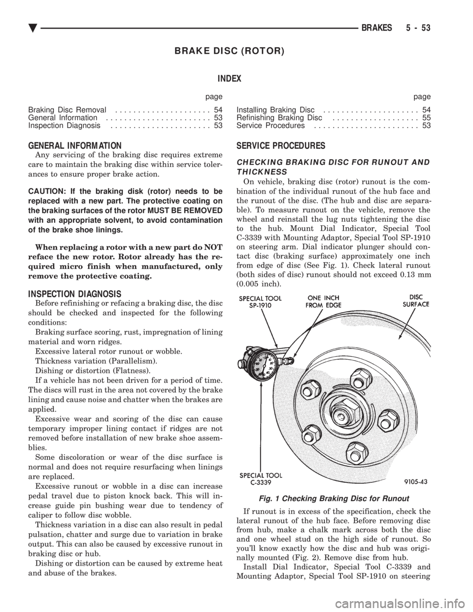
On vehicle, braking disc (rotor) runout is the com-
bination of the individual runout of the hub face and
the runout of the disc. (The hub and disc are separa-
ble). To measure runout on the vehicle, remove the
wheel and reinstall the lug nuts tightening the disc
to the hub. Mount Dial Indicator, Special Tool
C-3339 with Mounting Adaptor, Special Tool SP-1910
on steering arm. Dial indicator plunger should con-
tact disc (braking surface) approximately one inch
from edge of disc (See Fig. 1). Check lateral runout
(both sides of disc) runout should not exceed 0.13 mm
(0.005 inch).
If runout is in excess of the specification, check the
lateral runout of the hub face. Before removing disc
from hub, make a chalk mark across both the disc
and one wheel stud on the high side of runout. So
you'll know exactly how the disc and hub was origi-
nally mounted (Fig. 2). Remove disc from hub. Install Dial Indicator, Special Tool C-3339 and
Mounting Adaptor, Special Tool SP-1910 on steering
Fig. 1 Checking Braking Disc for Runout
Ä BRAKES 5 - 53