1993 CHEVROLET DYNASTY service
[x] Cancel search: servicePage 147 of 2438
REAR (STUB) AXLE ALIGNMENT ALL MODELS INDEX
page page
General Information ....................... 89 Rear Wheel Alignment..................... 89
GENERAL INFORMATION
Because front wheel drive vehicles are equipped with
rear suspension incorporating stub axles (or wheel
spindles). It is possible to align both the camber and toe
of the rear wheels.
REAR WHEEL ALIGNMENT
Alignment adjustment if required. Is made by adding
0.010 inch shims (from the service package kit) be-
tween the spindle mounting surface and axle mounting
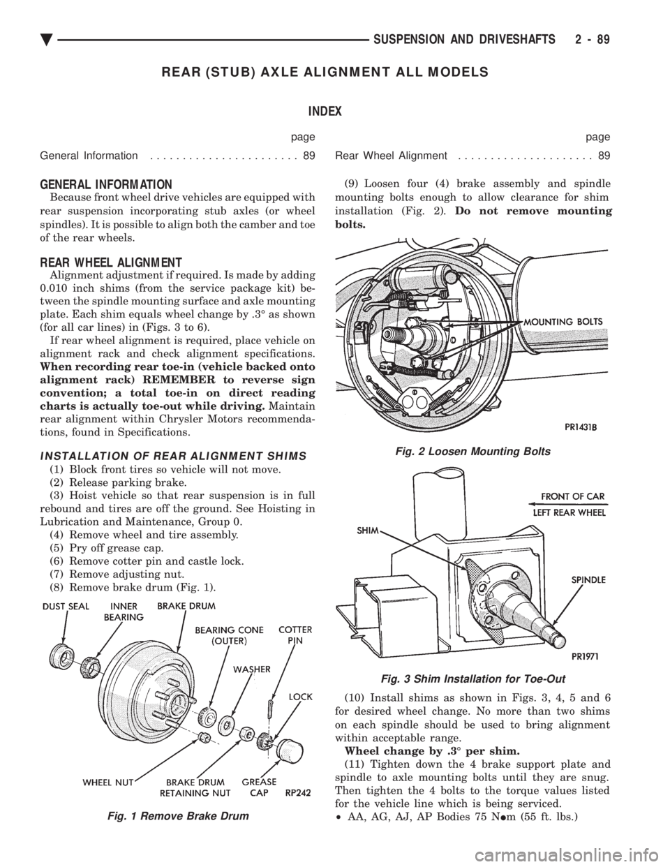
plate. Each shim equals wheel change by .3É as shown
(for all car lines) in (Figs. 3 to 6). If rear wheel alignment is required, place vehicle on
alignment rack and check alignment specifications.
When recording rear toe-in (vehicle backed onto
alignment rack) REMEMBER to reverse sign
convention; a total toe-in on direct reading
charts is actually toe-out while driving. Maintain
rear alignment within Chrysler Motors recommenda-
tions, found in Specifications.
INSTALLATION OF REAR ALIGNMENT SHIMS
(1) Block front tires so vehicle will not move.
(2) Release parking brake.
(3) Hoist vehicle so that rear suspension is in full
rebound and tires are off the ground. See Hoisting in
Lubrication and Maintenance, Group 0. (4) Remove wheel and tire assembly.
(5) Pry off grease cap.
(6) Remove cotter pin and castle lock.
(7) Remove adjusting nut.
(8) Remove brake drum (Fig. 1). (9) Loosen four (4) brake assembly and spindle
mounting bolts enough to allow clearance for shim
installation (Fig. 2). Do not remove mounting
bolts.
(10) Install shims as shown in Figs. 3, 4, 5 and 6
for desired wheel change. No more than two shims
on each spindle should be used to bring alignment
within acceptable range. Wheel change by .3É per shim.
(11) Tighten down the 4 brake support plate and
spindle to axle mounting bolts until they are snug.
Then tighten the 4 bolts to the torque values listed
for the vehicle line which is being serviced.
² AA, AG, AJ, AP Bodies 75 N Im (55 ft. lbs.)
Fig. 2 Loosen Mounting Bolts
Fig. 3 Shim Installation for Toe-Out
Fig. 1 Remove Brake Drum
Ä SUSPENSION AND DRIVESHAFTS 2 - 89
Page 151 of 2438

BRAKES
CONTENTS
page page
ANTI-LOCK BRAKE SYSTEMÐBENDIX ANTI-LOCK 10 AC/Y BODY ............. 72
ANTI-LOCK BRAKE SYSTEMÐBENDIX ANTI-LOCK 6 AA,AG,AJ,AP BODY ....... 113
BRAKE DISC (ROTOR) ................... 53
BRAKE SUPPORT ASSEMBLY ............. 25
FRONT DISC BRAKES ................... 31
GENERAL INFORMATION .................. 1
HYDRAULIC SYSTEM CONTROL VALVES . . . 26
KELSEY HAYES DOUBLE PIN FAMILY CALIPER ............................ 35 KELSEY HAYES DOUBLE PIN NON-FAMILY
CALIPER ............................ 38
MASTER CYLINDER ..................... 66
PARKING BRAKES ...................... 57
POWER BRAKES ....................... 68
REAR DISC BRAKES .................... 45
REAR WHEEL DRUM BRAKES ............ 18
SERVICE ADJUSTMENTS .................. 4
WHEEL BEARINGS ...................... 70
WHEEL CYLINDERS ..................... 23
GENERAL INFORMATION
Throughout this group, references may be made to
a particular vehicle by letter or number designation.
A chart showing the break down of these designa-
tions is included in the Introduction Section at the
front of this service manual. Standard brake equipment consists of:
² Double pin floating caliper disc front brakes.
² Rear automatic adjusting drum brakes.
² Differential valve with a brake warning switch.
² Master cylinder.
² Vacuum power booster.
² Double pin floating caliper rear disc brakes are
available on some models. The Bendix Anti-Lock 10 braking system, uses the
standard power brake system caliper assemblies,
braking discs, pedal assembly, brake lines and hoses.
The unique parts of the Bendix Anti-Lock 10 braking
system consists of the following components. Propor-
tioning valves, wheel speed sensors, tone wheels,
electronic control unit, modulator assembly and hy-
draulic assembly. These components replace the con-
ventional master cylinder and power booster. The
components will be described in detail in the Bendix
Anti-Lock 10 brake section in this group of the ser-
vice manual. The Bendix Anti-Lock 6 braking system, uses the
following standard brake system components. Master
cylinder, power booster, caliper assemblies, braking
discs, pedal assembly, brake lines and hoses. The
unique parts of the Bendix Anti-Lock 6 braking sys-
tem consists of the following components. Modulator
assembly, unique proportioning valves, wheel speed
sensors, tone wheels, and electronic control unit.
These components will be described in detail in the
Bendix Anti-Lock 6 brake section in this group of the
service manual. The front disc brake shoes have semi-metallic lin-
ings. The hydraulic brake system (Fig .123and4)is
diagonally split on both the Non-ABS and ABS brak-
ing system. With the left front and right rear brakes
on one hydraulic system and the right front and left
rear on the other. The Non-ABS and ABS brake system may use dif-
ferent types of brake line fittings and tubing flares.
The Non-ABS brake system uses double wall tubing
flares and fittings at all tubing joint locations. Some
ABS brake systems use both ISO style tubing flares
and double wall tubing flares and corresponding fit-
tings at different joint locations. See (Figs . 2 3 and 4)
for specific joint locations and type of tubing flare. The front disc brakes consist of two different types
of caliper assemblies. A double pin Kelsey-Hayes cal-
iper (family caliper) with a bolt-on adapter attached
to the steering knuckle. Or a double pin Kelsey-
Hayes caliper (non-family caliper) which mounts di-
rectly to rails on the steering knuckle. The non-
family caliper is only used on the AY Body
(Imperials).
CAUTION: Caliper pistons, boots and seals for the
different caliper assemblies used on the front and
rear disc brake assemblies are not interchangeable.
Misusage could result in a complete brake system
failure. Be sure that the parts are replaced with the
correct replacement parts, refer to the parts book
for the type and model year of the vehicle being
worked on.
The master cylinder is anodized, lightweight alu-
minum, with a bore size of 24.0mm, 21.0mm or 7/8
inch.
Ä BRAKES 5 - 1
Page 154 of 2438
SERVICE ADJUSTMENTS INDEX
page page
Adjusting Rear Service Brakes ............... 4
Bleeding Brake System ..................... 6
Brake Hose and Tubing ................... 11
Master Cylinder Fluid Level .................. 4 Stop Lamp Switch Adjustment (All Vehicles)
.... 13
Test for Fluid Contamination ................. 7
Testing Application Adjuster Operation ......... 6
Wheel Stud Nut Tightening .................. 7
MASTER CYLINDER FLUID LEVEL
ALL EXCEPT AC/AY BODY WITH ABS
Check master cylinder reservoir brake fluid level a
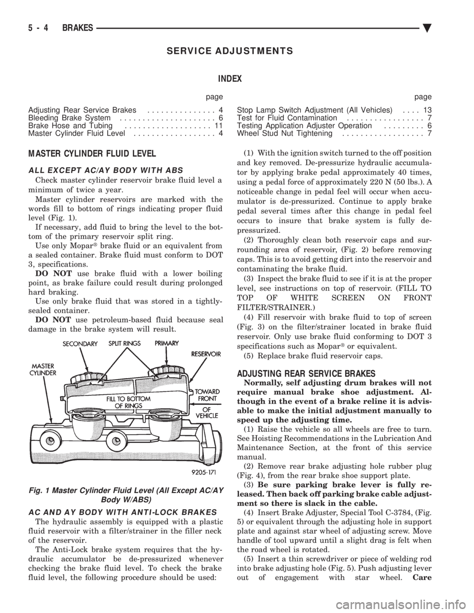
minimum of twice a year. Master cylinder reservoirs are marked with the
words fill to bottom of rings indicating proper fluid
level (Fig. 1). If necessary, add fluid to bring the level to the bot-
tom of the primary reservoir split ring. Use only Mopar tbrake fluid or an equivalent from
a sealed container. Brake fluid must conform to DOT
3, specifications. DO NOT use brake fluid with a lower boiling
point, as brake failure could result during prolonged
hard braking. Use only brake fluid that was stored in a tightly-
sealed container. DO NOT use petroleum-based fluid because seal
damage in the brake system will result.
AC AND AY BODY WITH ANTI-LOCK BRAKES
The hydraulic assembly is equipped with a plastic
fluid reservoir with a filter/strainer in the filler neck
of the reservoir. The Anti-Lock brake system requires that the hy-
draulic accumulator be de-pressurized whenever
checking the brake fluid level. To check the brake
fluid level, the following procedure should be used: (1) With the ignition switch turned to the off position
and key removed. De-pressurize hydraulic accumula-
tor by applying brake pedal approximately 40 times,
using a pedal force of approximately 220 N (50 lbs.). A
noticeable change in pedal feel will occur when accu-
mulator is de-pressurized. Continue to apply brake
pedal several times after this change in pedal feel
occurs to insure that brake system is fully de-
pressurized. (2) Thoroughly clean both reservoir caps and sur-
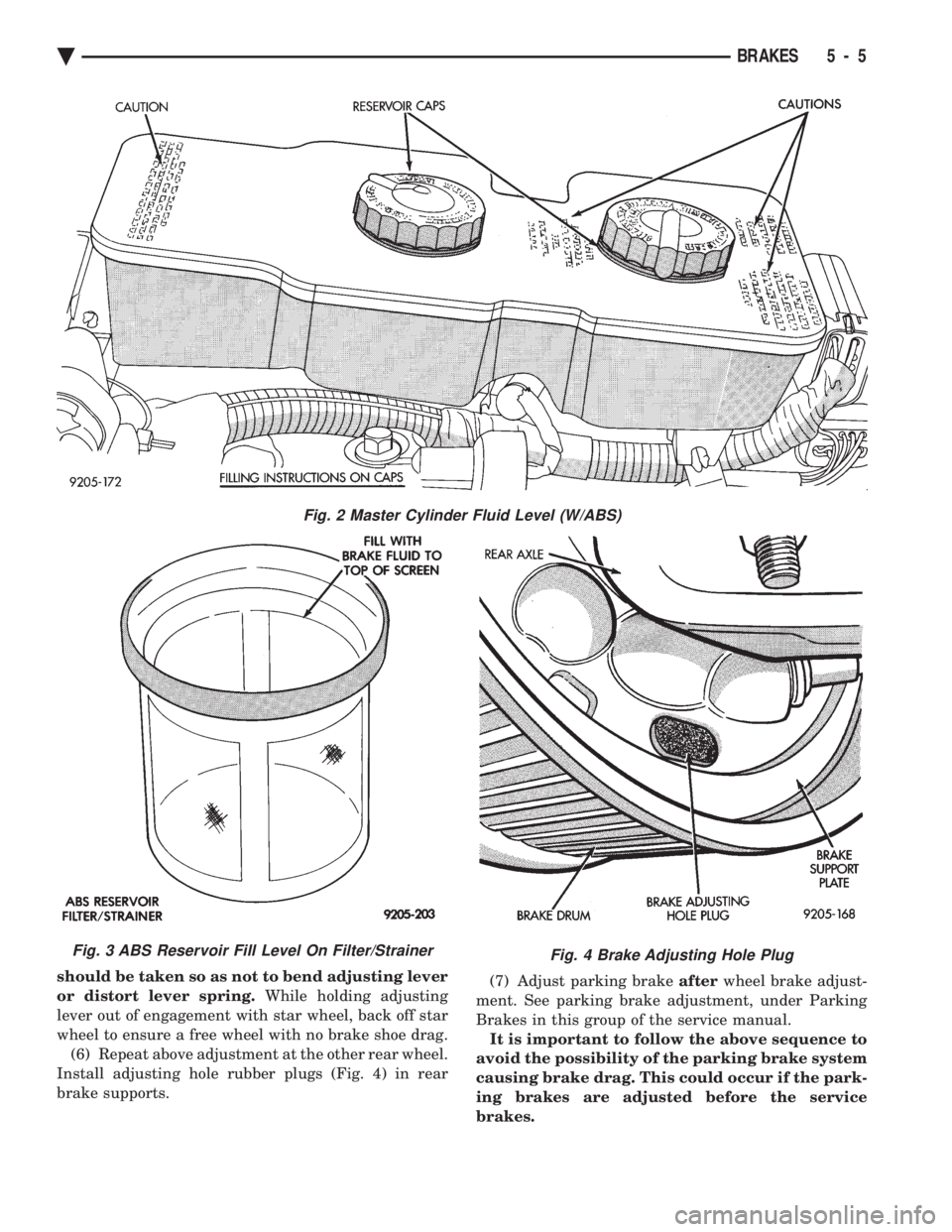
rounding area of reservoir, (Fig. 2) before removing
caps. This is to avoid getting dirt into the reservoir and
contaminating the brake fluid. (3) Inspect the brake fluid to see if it is at the proper
level, see instructions on top of reservoir. (FILL TO
TOP OF WHITE SCREEN ON FRONT
FILTER/STRAINER.) (4) Fill reservoir with brake fluid to top of screen
(Fig. 3) on the filter/strainer located in brake fluid
reservoir. Only use brake fluid conforming to DOT 3
specifications such as Mopar tor equivalent.
(5) Replace brake fluid reservoir caps.
ADJUSTING REAR SERVICE BRAKES
Normally, self adjusting drum brakes will not
require manual brake shoe adjustment. Al-
though in the event of a brake reline it is advis-
able to make the initial adjustment manually to
speed up the adjusting time. (1) Raise the vehicle so all wheels are free to turn.
See Hoisting Recommendations in the Lubrication And
Maintenance Section, at the front of this service
manual. (2) Remove rear brake adjusting hole rubber plug
(Fig. 4), from the rear brake shoe support plate. (3) Be sure parking brake lever is fully re-
leased. Then back off parking brake cable adjust-
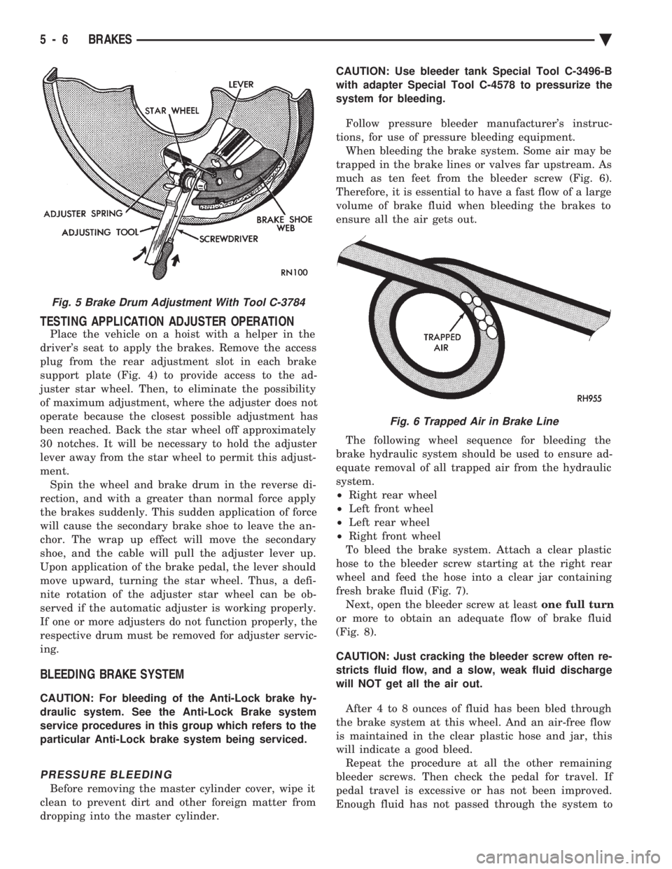
ment so there is slack in the cable. (4) Insert Brake Adjuster, Special Tool C-3784, (Fig.
5) or equivalent through the adjusting hole in support
plate and against star wheel of adjusting screw. Move
handle of tool upward until a slight drag is felt when
the road wheel is rotated. (5) Insert a thin screwdriver or piece of welding rod
into brake adjusting hole (Fig. 5). Push adjusting lever
out of engagement with star wheel. Care
Fig. 1 Master Cylinder Fluid Level (All Except AC/AY
Body W/ABS)
5 - 4 BRAKES Ä
Page 155 of 2438
should be taken so as not to bend adjusting lever
or distort lever spring. While holding adjusting
lever out of engagement with star wheel, back off star
wheel to ensure a free wheel with no brake shoe drag. (6) Repeat above adjustment at the other rear wheel.
Install adjusting hole rubber plugs (Fig. 4) in rear
brake supports. (7) Adjust parking brake
afterwheel brake adjust-
ment. See parking brake adjustment, under Parking
Brakes in this group of the service manual. It is important to follow the above sequence to
avoid the possibility of the parking brake system
causing brake drag. This could occur if the park-
ing brakes are adjusted before the service
brakes.
Fig. 4 Brake Adjusting Hole Plug
Fig. 2 Master Cylinder Fluid Level (W/ABS)
Fig. 3 ABS Reservoir Fill Level On Filter/Strainer
Ä BRAKES 5 - 5
Page 156 of 2438
TESTING APPLICATION ADJUSTER OPERATION
Place the vehicle on a hoist with a helper in the
driver's seat to apply the brakes. Remove the access
plug from the rear adjustment slot in each brake
support plate (Fig. 4) to provide access to the ad-
juster star wheel. Then, to eliminate the possibility
of maximum adjustment, where the adjuster does not
operate because the closest possible adjustment has
been reached. Back the star wheel off approximately
30 notches. It will be necessary to hold the adjuster
lever away from the star wheel to permit this adjust-
ment. Spin the wheel and brake drum in the reverse di-
rection, and with a greater than normal force apply
the brakes suddenly. This sudden application of force
will cause the secondary brake shoe to leave the an-
chor. The wrap up effect will move the secondary
shoe, and the cable will pull the adjuster lever up.
Upon application of the brake pedal, the lever should
move upward, turning the star wheel. Thus, a defi-
nite rotation of the adjuster star wheel can be ob-
served if the automatic adjuster is working properly.
If one or more adjusters do not function properly, the
respective drum must be removed for adjuster servic-
ing.
BLEEDING BRAKE SYSTEM
CAUTION: For bleeding of the Anti-Lock brake hy-
draulic system. See the Anti-Lock Brake system
service procedures in this group which refers to the
particular Anti-Lock brake system being serviced.
PRESSURE BLEEDING
Before removing the master cylinder cover, wipe it
clean to prevent dirt and other foreign matter from
dropping into the master cylinder. CAUTION: Use bleeder tank Special Tool C-3496-B
with adapter Special Tool C-4578 to pressurize the
system for bleeding.
Follow pressure bleeder manufacturer's instruc-
tions, for use of pressure bleeding equipment. When bleeding the brake system. Some air may be
trapped in the brake lines or valves far upstream. As
much as ten feet from the bleeder screw (Fig. 6).
Therefore, it is essential to have a fast flow of a large
volume of brake fluid when bleeding the brakes to
ensure all the air gets out.
The following wheel sequence for bleeding the
brake hydraulic system should be used to ensure ad-
equate removal of all trapped air from the hydraulic
system.
² Right rear wheel
² Left front wheel
² Left rear wheel
² Right front wheel
To bleed the brake system. Attach a clear plastic
hose to the bleeder screw starting at the right rear
wheel and feed the hose into a clear jar containing
fresh brake fluid (Fig. 7). Next, open the bleeder screw at least one full turn
or more to obtain an adequate flow of brake fluid
(Fig. 8).
CAUTION: Just cracking the bleeder screw often re-
stricts fluid flow, and a slow, weak fluid discharge
will NOT get all the air out.
After 4 to 8 ounces of fluid has been bled through
the brake system at this wheel. And an air-free flow
is maintained in the clear plastic hose and jar, this
will indicate a good bleed. Repeat the procedure at all the other remaining
bleeder screws. Then check the pedal for travel. If
pedal travel is excessive or has not been improved.
Enough fluid has not passed through the system to
Fig. 5 Brake Drum Adjustment With Tool C-3784
Fig. 6 Trapped Air in Brake Line
5 - 6 BRAKES Ä
Page 161 of 2438
BRAKE HOSE AND TUBING
INSPECTION OF BRAKE HOSE AND TUBING
Flexible rubber hose is used at both front brakes and
at the rear axle. Inspection of brake hoses should be
performed whenever the brake system is serviced and
every 7,500 miles or 12 months, whichever comes first
(every engine oil change). Inspect hydraulic brake
hoses for severe surface cracking, scuffing, or worn
spots. Should the fabric casing of the rubber hose be
exposed due to cracks or abrasions in the rubber hose
cover, the hose should be replaced immediately. Even-
tual deterioration of the hose can take place with
possible burst failure. Faulty installation can cause
twisting and wheel, tire or chassis interference. The steel brake tubing should be inspected periodi-
cally for evidence of physical damage or contact with
moving or hot components.
INSTALLATION OF BRAKE HOSE
Always use factory recommended brake hose to en-
sure quality, correct length and superior fatigue life.
Care should be taken to make sure that the tube and
hose mating surfaces are clean and free from nicks and
burrs. Front right and left side hoses are not
interchangeable. Connections should be correct and properly made.
Use new copper seal washers on all connections using
Banjo Bolts and tighten all fittings to their specified
torques. The flexible front hydraulic brake hose should al-
ways be installed on the vehicle by first attaching the
Banjo connector to the caliper assembly. Then bolt the
intermediate hose bracket to the strut assembly allow-
ing the bracket to position the hose to prevent twisting.
Attach the hose to the body bracket and steel brake
tubing. Tighten all fittings to specified torque. The
body bracket and hose end are keyed so that they will
only fit one way. Install rear brake hoses first to the trailing arm
tubes and then to the floor pan tubes. Minimize hose
twisting. Vehicles equipped with rear disc brakes have
brake hoses attached to the caliper on each side. The
brake hose should be first attached by the Banjo bolt to
the caliper and then secured to the hose bracket with
the retaining clip. The attach the steel brake tubing to
the hose fitting.
REPAIR AND INSTALLATION OF BRAKE TUB- ING
Only double wall 4.75mm (3/16 in.) steel tubing
should be used for replacement. Care should be taken
when replacing brake tubing, to be sure the proper
bending and flaring tools and procedures are used, to
avoid kinking. Do not route the tubes against sharp edges, moving components or into hot areas. All
tubes should be properly attached with recommended
retaining clips.
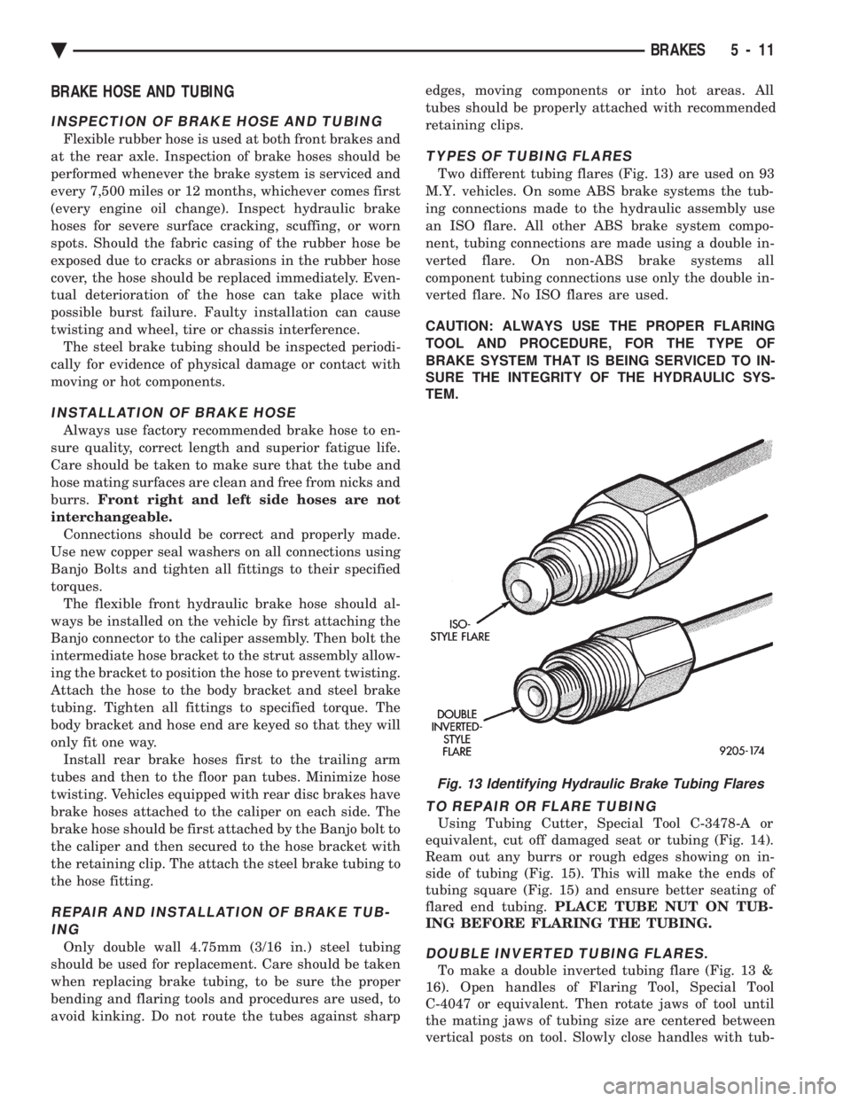
TYPES OF TUBING FLARES
Two different tubing flares (Fig. 13) are used on 93
M.Y. vehicles. On some ABS brake systems the tub-
ing connections made to the hydraulic assembly use
an ISO flare. All other ABS brake system compo-
nent, tubing connections are made using a double in-
verted flare. On non-ABS brake systems all
component tubing connections use only the double in-
verted flare. No ISO flares are used.
CAUTION: ALWAYS USE THE PROPER FLARING
TOOL AND PROCEDURE, FOR THE TYPE OF
BRAKE SYSTEM THAT IS BEING SERVICED TO IN-
SURE THE INTEGRITY OF THE HYDRAULIC SYS-
TEM.
TO REPAIR OR FLARE TUBING
Using Tubing Cutter, Special Tool C-3478-A or
equivalent, cut off damaged seat or tubing (Fig. 14).
Ream out any burrs or rough edges showing on in-
side of tubing (Fig. 15). This will make the ends of
tubing square (Fig. 15) and ensure better seating of
flared end tubing. PLACE TUBE NUT ON TUB-
ING BEFORE FLARING THE TUBING.
DOUBLE INVERTED TUBING FLARES.
To make a double inverted tubing flare (Fig. 13 &
16). Open handles of Flaring Tool, Special Tool
C-4047 or equivalent. Then rotate jaws of tool until
the mating jaws of tubing size are centered between
vertical posts on tool. Slowly close handles with tub-
Fig. 13 Identifying Hydraulic Brake Tubing Flares
Ä BRAKES 5 - 11
Page 162 of 2438
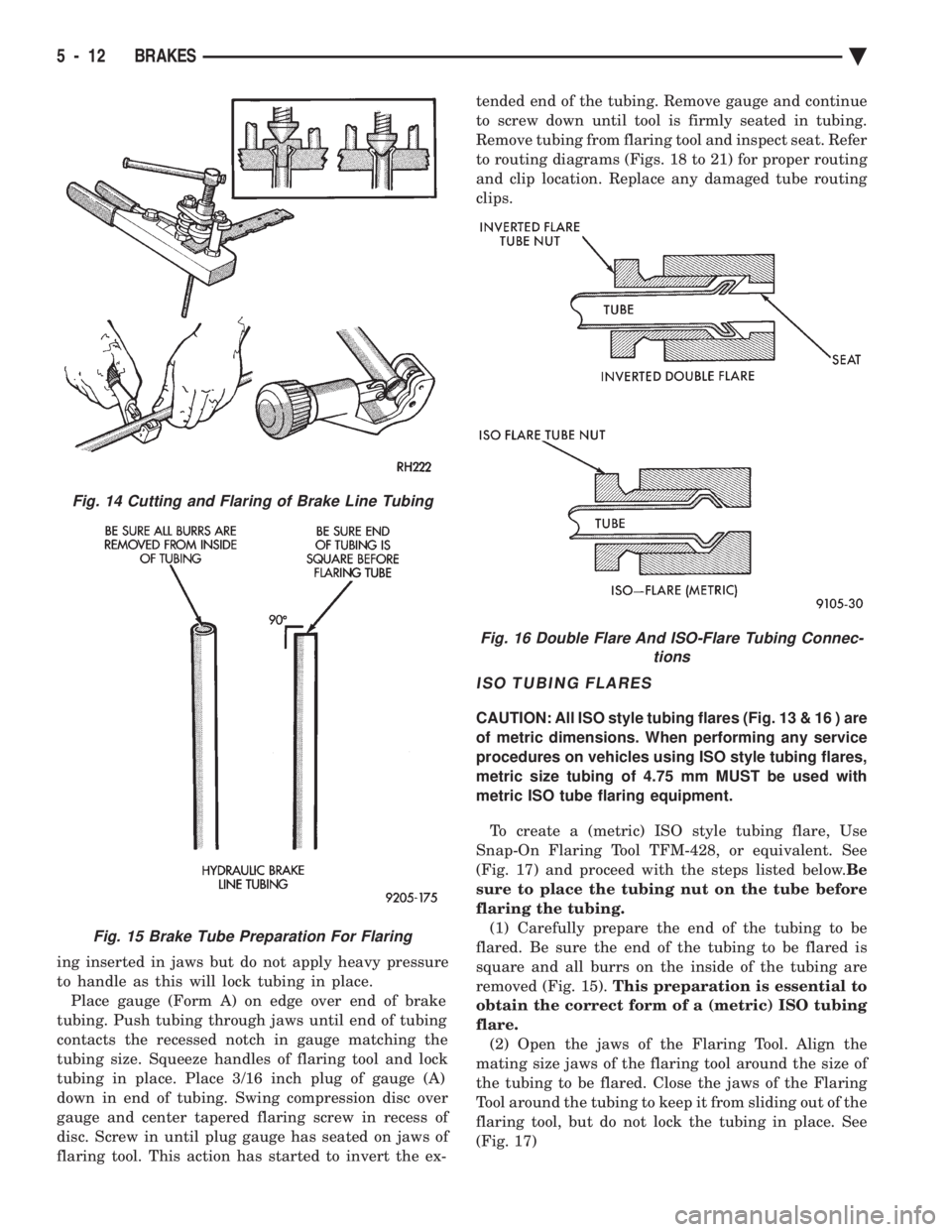
ing inserted in jaws but do not apply heavy pressure
to handle as this will lock tubing in place.Place gauge (Form A) on edge over end of brake
tubing. Push tubing through jaws until end of tubing
contacts the recessed notch in gauge matching the
tubing size. Squeeze handles of flaring tool and lock
tubing in place. Place 3/16 inch plug of gauge (A)
down in end of tubing. Swing compression disc over
gauge and center tapered flaring screw in recess of
disc. Screw in until plug gauge has seated on jaws of
flaring tool. This action has started to invert the ex- tended end of the tubing. Remove gauge and continue
to screw down until tool is firmly seated in tubing.
Remove tubing from flaring tool and inspect seat. Refer
to routing diagrams (Figs. 18 to 21) for proper routing
and clip location. Replace any damaged tube routing
clips.
ISO TUBING FLARES
CAUTION: All ISO style tubing flares (Fig. 13 & 16 ) are
of metric dimensions. When performing any service
procedures on vehicles using ISO style tubing flares,
metric size tubing of 4.75 mm MUST be used with
metric ISO tube flaring equipment.
To create a (metric) ISO style tubing flare, Use
Snap-On Flaring Tool TFM-428, or equivalent. See
(Fig. 17) and proceed with the steps listed below. Be
sure to place the tubing nut on the tube before
flaring the tubing. (1) Carefully prepare the end of the tubing to be
flared. Be sure the end of the tubing to be flared is
square and all burrs on the inside of the tubing are
removed (Fig. 15). This preparation is essential to
obtain the correct form of a (metric) ISO tubing
flare. (2) Open the jaws of the Flaring Tool. Align the
mating size jaws of the flaring tool around the size of
the tubing to be flared. Close the jaws of the Flaring
Tool around the tubing to keep it from sliding out of the
flaring tool, but do not lock the tubing in place. See
(Fig. 17)
Fig. 14 Cutting and Flaring of Brake Line Tubing
Fig. 15 Brake Tube Preparation For Flaring
Fig. 16 Double Flare And ISO-Flare Tubing Connec- tions
5 - 12 BRAKES Ä
Page 168 of 2438
REAR WHEEL DRUM BRAKES INDEX
page page
Brake Drum Refacing ..................... 21
Brake Shoe Assemblies ................... 19 Description
............................. 18
Service Procedures ....................... 18
DESCRIPTION
Rear wheel drum brakes (Fig .2&3)aretwoshoe,
internal expanding type with an automatic adjuster
screw assembly that is activated each time the
brakes are applied. The automatic adjuster screw is
located directly below the wheel cylinder as shown in
figure (Fig .2&3).
WARNING: DUST AND DIRT ON BRAKE PARTS
GENERATED DURING THE NORMAL USE AND
WEAR OF MOTOR VEHICLE BRAKE SYSTEMS MAY
CONTAIN ASBESTOS FIBERS. BREATHING EXCES-
SIVE CONCENTRATIONS OF ASBESTOS FIBERS
CAN CAUSE SERIOUS BODILY HARM, SUCH AS
ASBESTOSIS AND CANCER. EXTREME CARE
SHOULD BE EXERCISED WHILE SERVICING
BRAKE ASSEMBLIES OR COMPONENTS. DO NOT CLEAN BRAKE ASSEMBLIES OR COM-
PONENTS WITH COMPRESSED AIR OR BY DRY
BRUSHING; USE A VACUUM CLEANER SPECIFI-
CALLY RECOMMENDED FOR USE WITH ASBES-
TOS FIBERS. IF A SUITABLE VACUUM CLEANER IS
NOT AVAILABLE, CLEANING SHOULD BE DONE
WET USING A WATER DAMPENED CLOTH. DO NOT CREATE DUST BY SANDING, GRINDING,
AND/OR SHAVING BRAKE LININGS OR PADS UN-
LESS SUCH OPERATION IS DONE WHILE USING
PROPERLY EXHAUST VENTILATED EQUIPMENT. DISPOSE OF ALL DUST AND DIRT SUSPECTED
TO CONTAIN ANY ASBESTOS FIBERS IN SEALED
BAGS OR CONTAINERS TO MINIMIZE DUST EXPO-
SURE TO YOURSELF AND OTHERS. FOLLOW ALL RECOMMENDED PRACTICES PRE-
SCRIBED BY THE OCCUPATIONAL SAFETY AND
HEALTH ADMINISTRATION AND THE ENVIRON-
MENTAL PROTECTION AGENCY. FOR THE HAN-
DLING, PROCESSING, AND DISPOSITION OF DUST
OR DIRT WHICH MAY CONTAIN ASBESTOS FI-
BERS. IT IS RECOMMENDED NOT TO BREATH ANY
TYPE OF BRAKE LINING MATERIAL DUST EVEN
ASBESTOS FREE, DUE TO THE FIBROUS NATURE
OF THE MATERIALS BEING USED.
SERVICE PROCEDURES
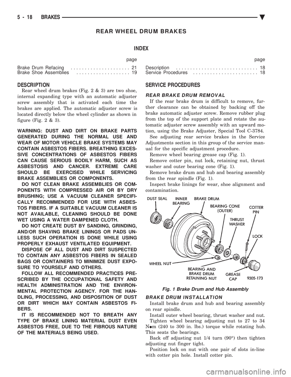
REAR BRAKE DRUM REMOVAL
If the rear brake drum is difficult to remove, fur-
ther clearance can be obtained by backing off the
brake automatic adjuster screw. Remove rubber plug
from the top of the support plate and rotate the au-
tomatic adjuster screw assembly with an upward mo-
tion, using the Brake Adjuster, Special Tool C-3784. See adjusting rear service brakes in the Service
Adjustments section in this group of the service man-
ual for the specific adjustment procedure. Remove wheel bearing grease cap (Fig. 1).
Remove cotter pin, nut lock, retaining nut, thrust
washer and outer bearing cone (Fig. 1). Remove brake drum and hub and bearing assembly
from the rear spindle (Fig. 1). Inspect brake linings for wear, shoe alignment and
contamination.
BRAKE DRUM INSTALLATION
Install brake drum and hub and bearing assembly
on rear spindle. Install outer wheel bearing, thrust washer and nut.
Tighten wheel bearing adjusting nut to 27 to 34
N Im (240 to 300 in. lbs.) torque while rotating hub.
This seats the bearings. Back off adjusting nut 1/4 turn (90É) then tighten
adjusting nut finger tight. Position lock on nut with one pair of slots in-line
with cotter pin hole. Install cotter pin.
Fig. 1 Brake Drum and Hub Assembly
5 - 18 BRAKES Ä