1993 CHEVROLET DYNASTY service
[x] Cancel search: servicePage 85 of 2438
DRIVESHAFT IDENTIFICATION
Driveshafts are identified by the manufacturer. Vehi-
cles can be equipped with any of these driveshaft as-
semblies. Each assembly can be identified as shown in
(Fig. 2).
SERVICE PROCEDURES
Procedures for the removal and installation of the
driveshafts are essentially the same for all front
wheel drive vehicles. Each driveshaft has a spring
within the inboard Tripod C/V joint that maintains
constant engagement with the transaxle. This allows
the drive shaft to be removed without dismantling
part of the transaxle.
CAUTION: Boot sealing is vital to retain special lu-
bricants and to prevent foreign contaminants from
entering the C/V joint. Mishandling, such as allow-
ing the assemblies to dangle unsupported, pulling
or pushing the ends can cut boots or damage C/V
joints. During removal and installation procedures
always support both ends of the driveshaft to pre-
vent damage.
DRIVESHAFTS, REMOVE INSTALL
HUB NUT REMOVAL
Hub nut removal and installation is the same for
all front wheel drive vehicles. For installation see
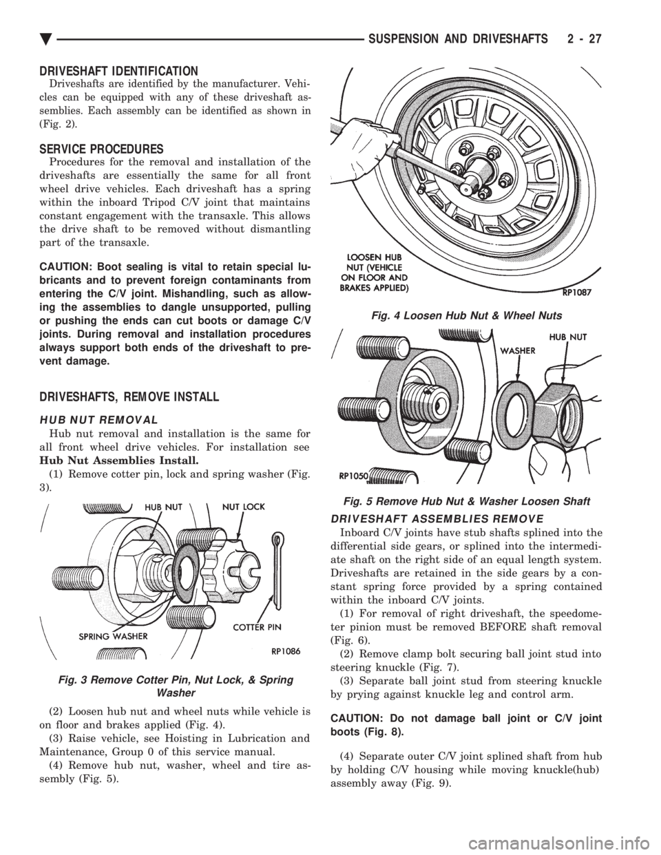
Hub Nut Assemblies Install. (1) Remove cotter pin, lock and spring washer (Fig.
3).
(2) Loosen hub nut and wheel nuts while vehicle is
on floor and brakes applied (Fig. 4). (3) Raise vehicle, see Hoisting in Lubrication and
Maintenance, Group 0 of this service manual. (4) Remove hub nut, washer, wheel and tire as-
sembly (Fig. 5).
DRIVESHAFT ASSEMBLIES REMOVE
Inboard C/V joints have stub shafts splined into the
differential side gears, or splined into the intermedi-
ate shaft on the right side of an equal length system.
Driveshafts are retained in the side gears by a con-
stant spring force provided by a spring contained
within the inboard C/V joints. (1) For removal of right driveshaft, the speedome-
ter pinion must be removed BEFORE shaft removal
(Fig. 6). (2) Remove clamp bolt securing ball joint stud into
steering knuckle (Fig. 7). (3) Separate ball joint stud from steering knuckle
by prying against knuckle leg and control arm.
CAUTION: Do not damage ball joint or C/V joint
boots (Fig. 8). (4) Separate outer C/V joint splined shaft from hub
by holding C/V housing while moving knuckle(hub)
assembly away (Fig. 9).
Fig. 3 Remove Cotter Pin, Nut Lock, & Spring Washer
Fig. 4 Loosen Hub Nut & Wheel Nuts
Fig. 5 Remove Hub Nut & Washer Loosen Shaft
Ä SUSPENSION AND DRIVESHAFTS 2 - 27
Page 87 of 2438
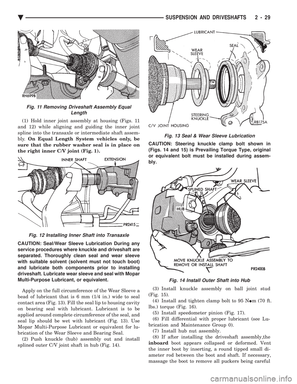
(1) Hold inner joint assembly at housing (Figs. 11
and 12) while aligning and guiding the inner joint
spline into the transaxle or intermediate shaft assem-
bly. On Equal Length System vehicles only, be
sure that the rubber washer seal is in place on
the right inner C/V joint (Fig. 1).
CAUTION: Seal/Wear Sleeve Lubrication During any
service procedures where knuckle and driveshaft are
separated. Thoroughly clean seal and wear sleeve
with suitable solvent (solvent must not touch boot)
and lubricate both components prior to installing
driveshaft. Lubricate wear sleeve and seal with Mopar
Multi-Purpose Lubricant, or equivalent.
Apply on the full circumference of the Wear Sleeve a
bead of lubricant that is 6 mm (1/4 in.) wide to seal
contact area (Fig. 13). Fill the seal lip to housing cavity
on bearing seal with lubricant. Lubricant is to be
applied around complete circumference of the seal, and
seal lip should be wet with lubricant (Fig. 13). Use
Mopar Multi-Purpose Lubricant or equivalent for lu-
brication of the Wear Sleeve and Bearing Seal. (2) Push knuckle (hub) assembly out and install
splined outer C/V joint shaft in hub (Fig. 14). CAUTION: Steering knuckle clamp bolt shown in
(Figs. 14 and 15) is Prevailing Torque Type, original
or equivalent bolt must be installed during assem-
bly.
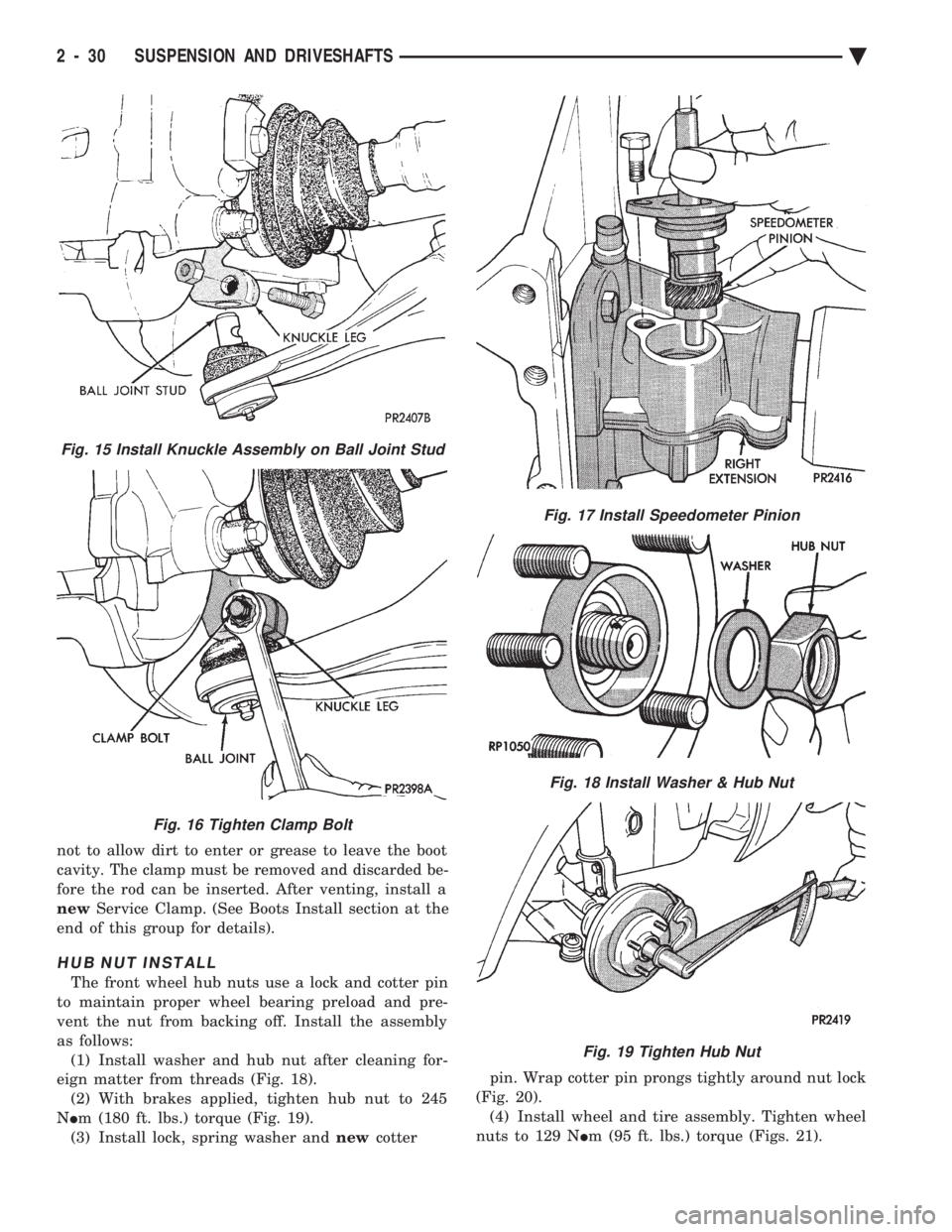
(3) Install knuckle assembly on ball joint stud
(Fig. 15). (4) Install and tighten clamp bolt to 95 N Im (70 ft.
lbs.) torque (Fig. 16). (5) Install speedometer pinion (Fig. 17).
(6) Fill differential with proper lubricant (see Lu-
brication and Maintenance Group 0). (7) Install hub nut assembly.
(8) If after installing the driveshaft assembly,the
inboard boot appears collapsed or deformed. Vent
the inner boot by inserting, a round tipped small di-
ameter rod between the boot and shaft. If necessary,
massage the boot to remove all puckers being careful
Fig. 13 Seal & Wear Sleeve Lubrication
Fig. 14 Install Outer Shaft into Hub
Fig. 11 Removing Driveshaft Assembly Equal Length
Fig. 12 Installing Inner Shaft into Transaxle
Ä SUSPENSION AND DRIVESHAFTS 2 - 29
Page 88 of 2438
not to allow dirt to enter or grease to leave the boot
cavity. The clamp must be removed and discarded be-
fore the rod can be inserted. After venting, install a
new Service Clamp. (See Boots Install section at the
end of this group for details).
HUB NUT INSTALL
The front wheel hub nuts use a lock and cotter pin
to maintain proper wheel bearing preload and pre-
vent the nut from backing off. Install the assembly
as follows: (1) Install washer and hub nut after cleaning for-
eign matter from threads (Fig. 18). (2) With brakes applied, tighten hub nut to 245
N Im (180 ft. lbs.) torque (Fig. 19).
(3) Install lock, spring washer and newcotter pin. Wrap cotter pin prongs tightly around nut lock
(Fig. 20). (4) Install wheel and tire assembly. Tighten wheel
nuts to 129 N Im (95 ft. lbs.) torque (Figs. 21).
Fig. 15 Install Knuckle Assembly on Ball Joint Stud
Fig. 16 Tighten Clamp Bolt
Fig. 17 Install Speedometer Pinion
Fig. 18 Install Washer & Hub Nut
Fig. 19 Tighten Hub Nut
2 - 30 SUSPENSION AND DRIVESHAFTS Ä
Page 89 of 2438
DRIVESHAFT RECONDITIONING PROCEDURE
Driveshaft reconditioning and/or boot replacement
for all front wheel drive vehicles is essentially the same
per C/V joint. Note: that lubricant requirements and quanti-
ties are different for Inner Joints than for Outer
Joints, and type being serviced. Use only the
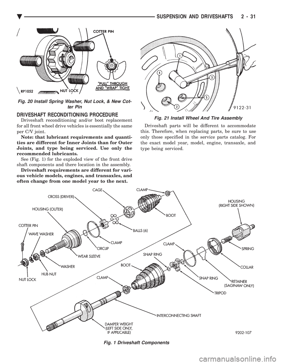
recommended lubricants. See (Fig. 1) for the exploded view of the front drive
shaft components and there location in the assembly. Driveshaft requirements are different for vari-
ous vehicle models, engines, and transaxles, and
often change from one model year to the next. Driveshaft parts will be different to accommodate
this. Therefore, when replacing parts, be sure to use
only those specified in the service parts catalog. For
the exact model year, model, engine, transaxle, and
type being serviced.
Fig. 1 Driveshaft Components
Fig. 21 Install Wheel And Tire Assembly
Fig. 20 Install Spring Washer, Nut Lock, & New Cot- ter Pin
Ä SUSPENSION AND DRIVESHAFTS 2 - 31
Page 100 of 2438
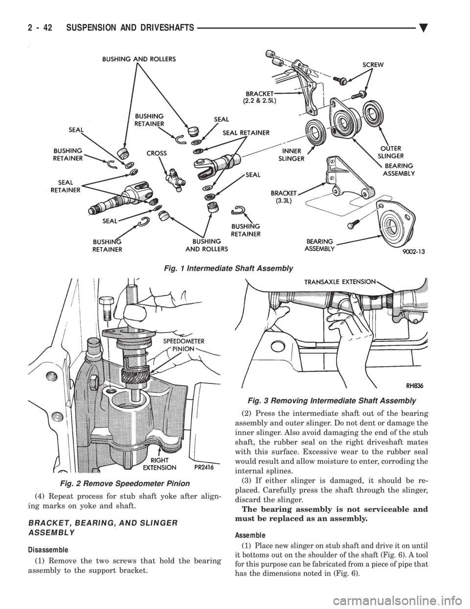
(4) Repeat process for stub shaft yoke after align-
ing marks on yoke and shaft.
BRACKET, BEARING, AND SLINGER ASSEMBLY
Disassemble
(1) Remove the two screws that hold the bearing
assembly to the support bracket. (2) Press the intermediate shaft out of the bearing
assembly and outer slinger. Do not dent or damage the
inner slinger. Also avoid damaging the end of the stub
shaft, the rubber seal on the right driveshaft mates
with this surface. Excessive wear to the rubber seal
would result and allow moisture to enter, corroding the
internal splines. (3) If either slinger is damaged, it should be re-
placed. Carefully press the shaft through the slinger,
discard the slinger. The bearing assembly is not serviceable and
must be replaced as an assembly.
Assemble(1) Place new slinger on stub shaft and drive it on until
it bottoms out on the shoulder of the shaft (Fig. 6). A tool
for this purpose can be fabricated from a piece of pipe that
has the dimensions noted in (Fig. 6).
Fig. 1 Intermediate Shaft Assembly
Fig. 2 Remove Speedometer Pinion
Fig. 3 Removing Intermediate Shaft Assembly
2 - 42 SUSPENSION AND DRIVESHAFTS Ä
Page 102 of 2438
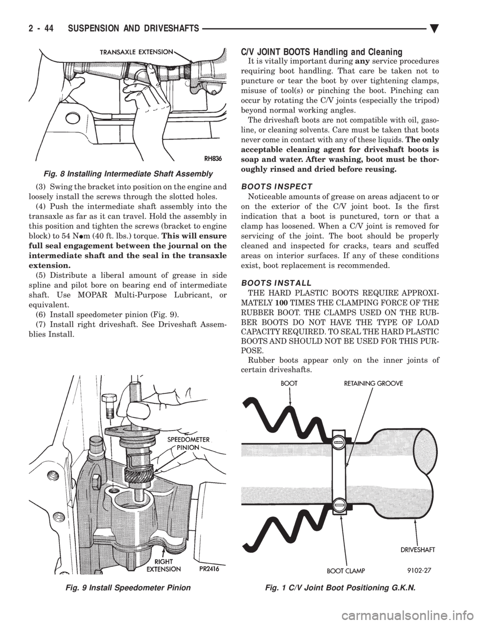
(3) Swing the bracket into position on the engine and
loosely install the screws through the slotted holes. (4) Push the intermediate shaft assembly into the
transaxle as far as it can travel. Hold the assembly in
this position and tighten the screws (bracket to engine
block) to 54 N Im (40 ft. lbs.) torque. This will ensure
full seal engagement between the journal on the
intermediate shaft and the seal in the transaxle
extension. (5) Distribute a liberal amount of grease in side
spline and pilot bore on bearing end of intermediate
shaft. Use MOPAR Multi-Purpose Lubricant, or
equivalent. (6) Install speedometer pinion (Fig. 9).
(7) Install right driveshaft. See Driveshaft Assem-
blies Install.
C/V JOINT BOOTS Handling and Cleaning
It is vitally important during anyservice procedures
requiring boot handling. That care be taken not to
puncture or tear the boot by over tightening clamps,
misuse of tool(s) or pinching the boot. Pinching can
occur by rotating the C/V joints (especially the tripod)
beyond normal working angles.
The driveshaft boots are not compatible with oil, gaso-
line, or cleaning solvents. Care must be taken that boots
never come in contact with any of these liquids. The only
acceptable cleaning agent for driveshaft boots is
soap and water. After washing, boot must be thor-
oughly rinsed and dried before reusing.
BOOTS INSPECT
Noticeable amounts of grease on areas adjacent to or
on the exterior of the C/V joint boot. Is the first
indication that a boot is punctured, torn or that a
clamp has loosened. When a C/V joint is removed for
servicing of the joint. The boot should be properly
cleaned and inspected for cracks, tears and scuffed
areas on interior surfaces. If any of these conditions
exist, boot replacement is recommended.
BOOTS INSTALL
THE HARD PLASTIC BOOTS REQUIRE APPROXI-
MATELY 100TIMES THE CLAMPING FORCE OF THE
RUBBER BOOT. THE CLAMPS USED ON THE RUB-
BER BOOTS DO NOT HAVE THE TYPE OF LOAD
CAPACITY REQUIRED. TO SEAL THE HARD PLASTIC
BOOTS AND SHOULD NOT BE USED FOR THIS PUR-
POSE.
Rubber boots appear only on the inner joints of
certain driveshafts.
Fig. 9 Install Speedometer PinionFig. 1 C/V Joint Boot Positioning G.K.N.
Fig. 8 Installing Intermediate Shaft Assembly
2 - 44 SUSPENSION AND DRIVESHAFTS Ä
Page 103 of 2438
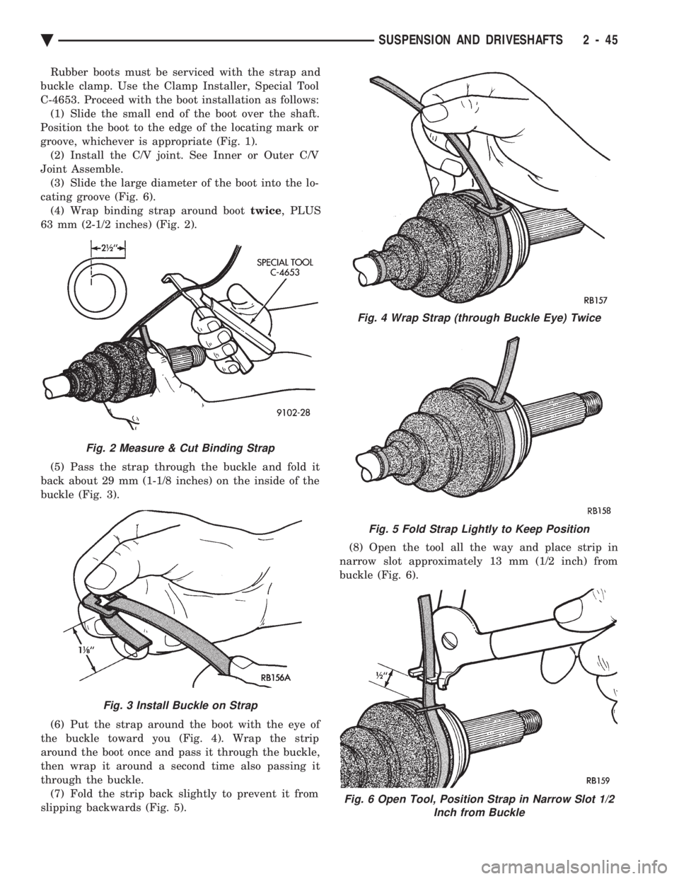
Rubber boots must be serviced with the strap and
buckle clamp. Use the Clamp Installer, Special Tool
C-4653. Proceed with the boot installation as follows: (1) Slide the small end of the boot over the shaft.
Position the boot to the edge of the locating mark or
groove, whichever is appropriate (Fig. 1). (2) Install the C/V joint. See Inner or Outer C/V
Joint Assemble. (3) Slide the large diameter of the boot into the lo-
cating groove (Fig. 6). (4) Wrap binding strap around boot twice, PLUS
63 mm (2-1/2 inches) (Fig. 2).
(5) Pass the strap through the buckle and fold it
back about 29 mm (1-1/8 inches) on the inside of the
buckle (Fig. 3).
(6) Put the strap around the boot with the eye of
the buckle toward you (Fig. 4). Wrap the strip
around the boot once and pass it through the buckle,
then wrap it around a second time also passing it
through the buckle. (7) Fold the strip back slightly to prevent it from
slipping backwards (Fig. 5). (8) Open the tool all the way and place strip in
narrow slot approximately 13 mm (1/2 inch) from
buckle (Fig. 6).
Fig. 2 Measure & Cut Binding Strap
Fig. 3 Install Buckle on Strap
Fig. 4 Wrap Strap (through Buckle Eye) Twice
Fig. 5 Fold Strap Lightly to Keep Position
Fig. 6 Open Tool, Position Strap in Narrow Slot 1/2 Inch from Buckle
Ä SUSPENSION AND DRIVESHAFTS 2 - 45
Page 106 of 2438
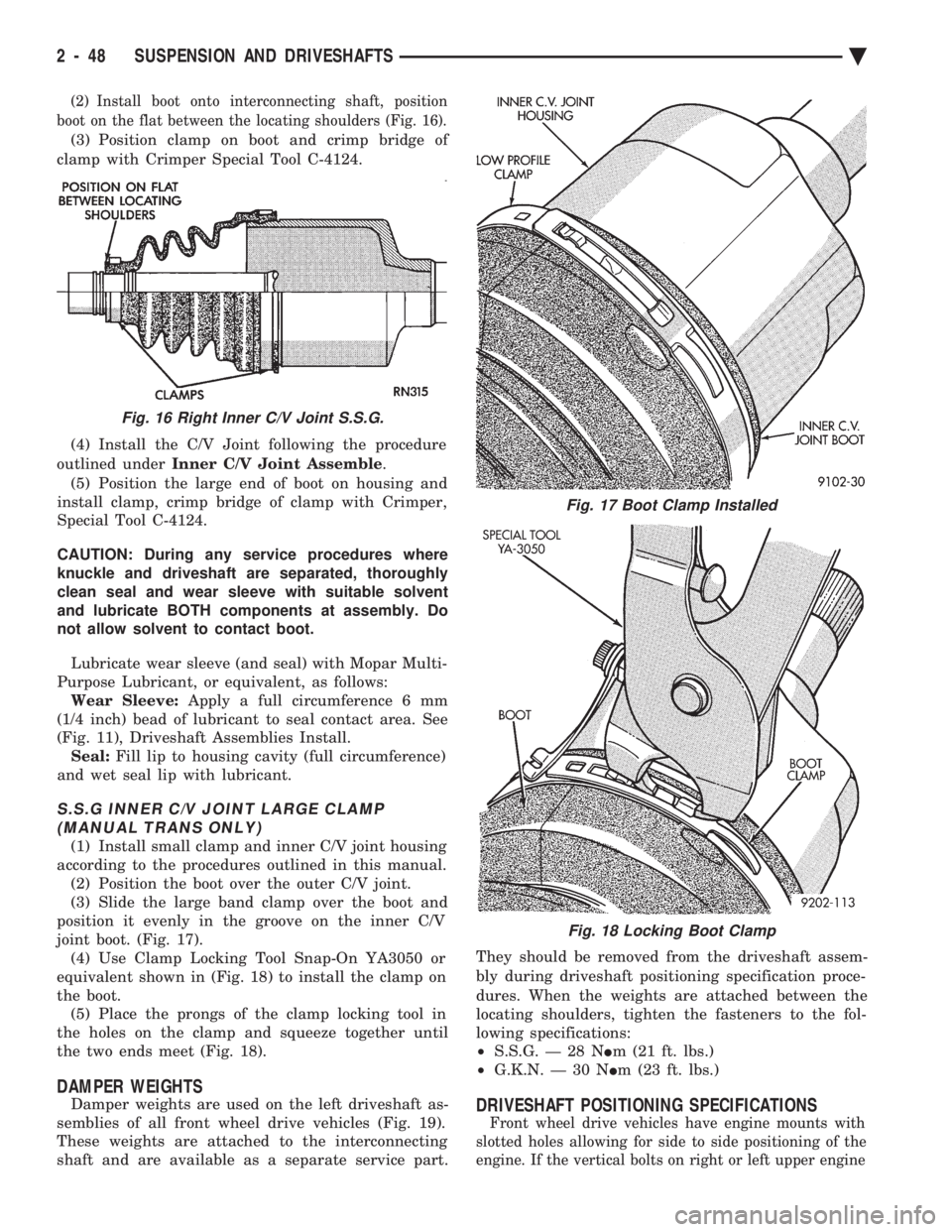
(2) Install boot onto interconnecting shaft, position
boot on the flat between the locating shoulders (Fig. 16).
(3) Position clamp on boot and crimp bridge of
clamp with Crimper Special Tool C-4124.
(4) Install the C/V Joint following the procedure
outlined under Inner C/V Joint Assemble .
(5) Position the large end of boot on housing and
install clamp, crimp bridge of clamp with Crimper,
Special Tool C-4124.
CAUTION: During any service procedures where
knuckle and driveshaft are separated, thoroughly
clean seal and wear sleeve with suitable solvent
and lubricate BOTH components at assembly. Do
not allow solvent to contact boot.
Lubricate wear sleeve (and seal) with Mopar Multi-
Purpose Lubricant, or equivalent, as follows: Wear Sleeve: Apply a full circumference 6 mm
(1/4 inch) bead of lubricant to seal contact area. See
(Fig. 11), Driveshaft Assemblies Install. Seal: Fill lip to housing cavity (full circumference)
and wet seal lip with lubricant.
S.S.G INNER C/V JOINT LARGE CLAMP (MANUAL TRANS ONLY)
(1) Install small clamp and inner C/V joint housing
according to the procedures outlined in this manual. (2) Position the boot over the outer C/V joint.
(3) Slide the large band clamp over the boot and
position it evenly in the groove on the inner C/V
joint boot. (Fig. 17). (4) Use Clamp Locking Tool Snap-On YA3050 or
equivalent shown in (Fig. 18) to install the clamp on
the boot. (5) Place the prongs of the clamp locking tool in
the holes on the clamp and squeeze together until
the two ends meet (Fig. 18).
DAMPER WEIGHTS
Damper weights are used on the left driveshaft as-
semblies of all front wheel drive vehicles (Fig. 19).
These weights are attached to the interconnecting
shaft and are available as a separate service part. They should be removed from the driveshaft assem-
bly during driveshaft positioning specification proce-
dures. When the weights are attached between the
locating shoulders, tighten the fasteners to the fol-
lowing specifications:
² S.S.G. Ð 28 N Im (21 ft. lbs.)
² G.K.N. Ð 30 N Im (23 ft. lbs.)DRIVESHAFT POSITIONING SPECIFICATIONS
Front wheel drive vehicles have engine mounts with
slotted holes allowing for side to side positioning of the
engine. If the vertical bolts on right or left upper engine
Fig. 16 Right Inner C/V Joint S.S.G.
Fig. 17 Boot Clamp Installed
Fig. 18 Locking Boot Clamp
2 - 48 SUSPENSION AND DRIVESHAFTS Ä