Page 1145 of 1216

24-l
HEATERS ANDAIR CONDITIONING
CONTENTSN24M--AIR CONDITIONER SWITCH
..........................30BLOWER ASSEMBLY
.....................................33
COMPRESSOR.................................................37CONDENSER AND CONDENSER FAN
MOTOR............................................................45ENGINE COOLANT TEMPERATURE
-‘-.,SWITCH............................................................51
EVAPORATOR.................................................
34
HEATERCONTROLASSEMBLY....................
26HEATER UNIT
.................................................31
REFRIGERANTLINE........................................47
RESISTOR........................................................29SAFETY PRECAUTIONS
.................................10SERVICE ADJUSTMENT PROCEDURES..
.....11Compressor Drive
Belt Adjustment
.............
23
CompressorNoise........................................24
Handling
TubingandFittings.......................22Idle-up
OperationCheck..............................25Manifold
GaugeSetInstallation..................11Performance Test
.........................................16Power Relay Check
......................................24Refrigerant Leak Repair Procedure
.............17
TestingSystemforLeaks...........................15Test Procedures
...........................................11
SPECIFICATIONS.............................................2
General Specifications..................................2
Lubricants......................................................3Sealant and Adhesives
.................................3Service Specifications
...................................2
TorqueSpecifications...................................2
TROUBLESHOOTING. . . ..a................................3
VENTILATORS(AIR INLET AND AIR OUTLET)
..,....s............. 50
VENTILATORS(INSTRUMENT PANEL)
..,...................*...........49
Page 1146 of 1216

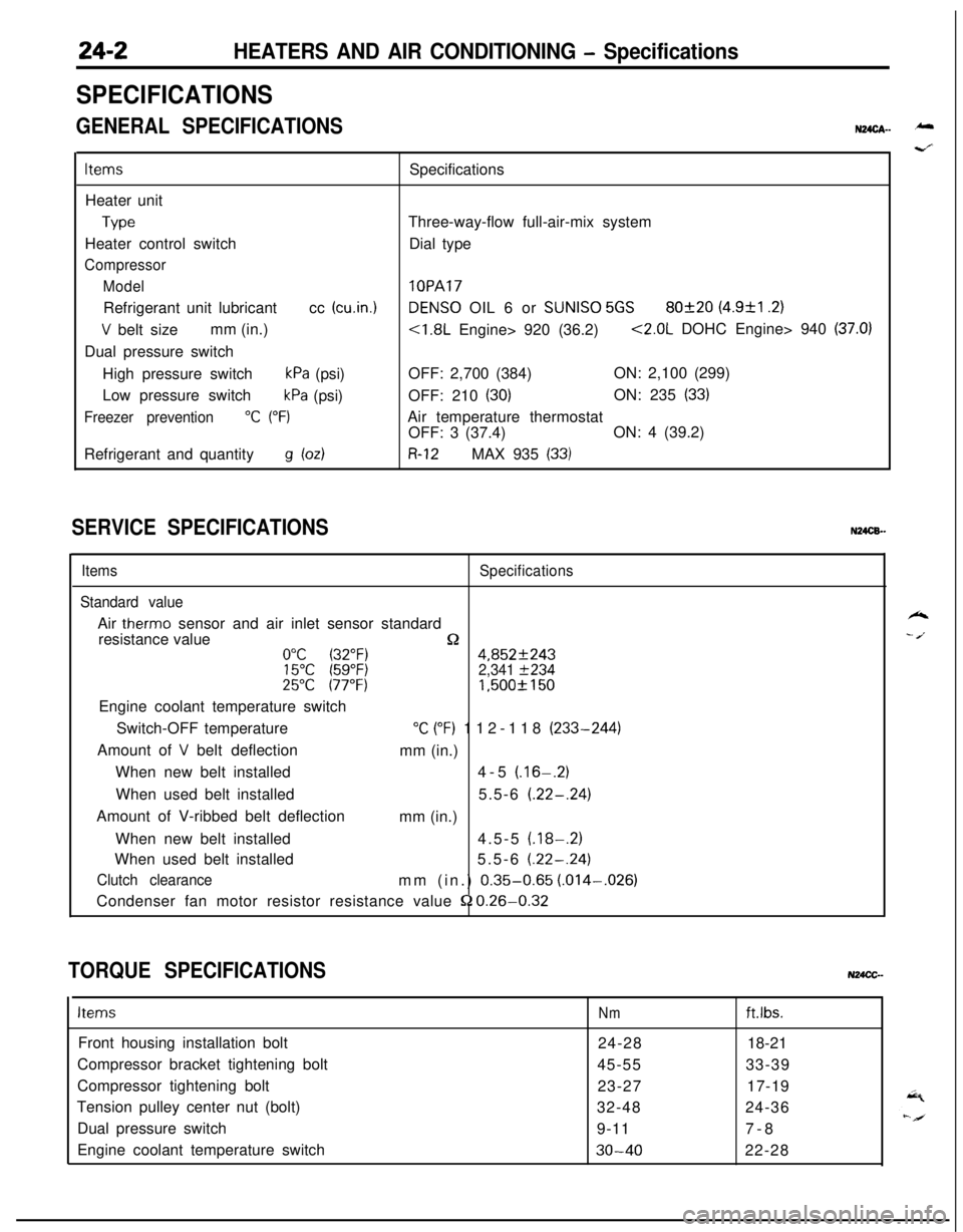
24-2HEATERS AND AIR CONDITIONING - Specifications
SPECIFICATIONS
GENERAL SPECIFICATIONSN24cA- -
ItemsSpecifications
Heater unit
TypeThree-way-flow full-air-mix system
Heater control switchDial type
Compressor
Model
lOPARefrigerant unit lubricantcc
(cu.in.1DENS0 OIL 6 or SUNISO 5GS80f20 (4.9&l .2)
V belt sizemm (in.)<1.8L Engine> 920 (36.2)<2.0L DOHC Engine> 940 (37.0)Dual pressure switch
High pressure switch
kPa (psi)OFF: 2,700 (384)ON: 2,100 (299)
Low pressure switch
kPa (psi)OFF: 210 (30)ON: 235 (33)
Freezer prevention“C (“F)Air temperature thermostat
OFF: 3 (37.4)ON: 4 (39.2)
Refrigerant and quantity
g bdR-12MAX 935 (33)
SERVICE SPECIFICATIONSN24CB.-
ItemsSpecifications
Standard valueAir
therm0 sensor and air inlet sensor standard
resistance value
n0°C (32°F)4,852f24315°C (59°F)2,341 f23425°C 177°F)1,500f 150Engine coolant temperature switch
Switch-OFF temperature
“C (“F) 112-118 (233-244)
Amount of
V belt deflection
mm (in.)
When new belt installed4-5
(.16-.2)When used belt installed5.5-6
(.22-.24)Amount of V-ribbed belt deflection
mm (in.)
When new belt installed4.5-5
(.18-.2)When used belt installed5.5-6
(.22-.24)
Clutch clearancemm (in.) 0.35-0.65 (.014-,026)
Condenser fan motor resistor resistance value
52 0.26-0.32
TORQUE SPECIFICATIONSN24CC-
ItemsNmft.lbs.Front housing installation bolt
24-2818-21
Compressor bracket tightening bolt
45-5533-39
Compressor tightening bolt
23-2717-19
Tension pulley center nut (bolt)
32-4824-36
Dual pressure switch
9-117-8
Engine coolant temperature switch
30-4022-28
k
- /.
Page 1197 of 1216

.^
EMISSION CONTROL
SYSTEMS
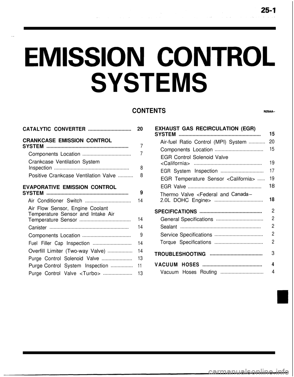
CONTENTSN25AA-
CATALYTICCONVERTER...............................20CRANKCASE EMISSION CONTROL
SYSTEM...........................................................7Components Location
...................................7Crankcase Ventilation System
Inspection......................................................8Positive Crankcase Ventilation Valve
...........8EVAPORATIVE EMISSION CONTROL
SYSTEM...........................................................9
AirConditionerSwitch.................................14Air Flow Sensor, Engine Coolant
Temperature Sensor and Intake Air
Temperature Sensor
.....................................14
Canister.........................................................14Components Location
...................................9
FuelFillerCapInspection............................14Overfill Limiter (Two-way Valve)
..................14
PurgeControlSolenoidValve......................13Purge Control
SystemInspection................11
PurgeControlValve.....................13EXHAUST GAS RECIRCULATION (EGR)
SYSTEM...........................................................15Air-fuel Ratio Control (MPI) System
............20Components Location
...................................15EGR Control Solenoid Valve
.................................................19
EGR
SystemInspection...............................17EGR Temperature Sensor
......19
EGR Valve.....................................................18
Therm0 Valve
2.0L DOHC Engine>...................................18
SPECIFICATIONS.............................................2General Specifications
..................................2
Sealant..........................................................2Service Specifications
...................................2
TorqueSpecifications...................................2
TROUBLESHOOTING......................................3
VACUUMHOSES...........................................4
VacuumHosesRouting...............................4
Page 1198 of 1216

EMISSION CONTROL SYSTEMS - Specifications
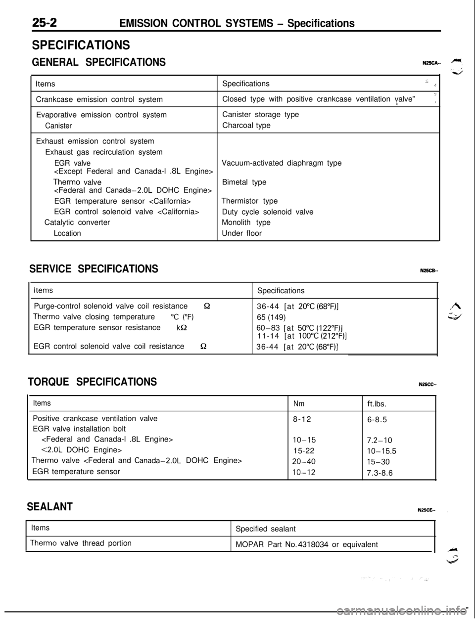
SPECIFICATIONS
GENERAL SPECIFICATIONSN25CA-ItemsSpecifications
.,:..rCrankcase emission control systemClosed type with positive crankcase ventilation valve”I
‘:Evaporative emission control systemCanister storage type
CanisterCharcoal type
Exhaust emission control system
Exhaust gas recirculation system
EGR valveVacuum-activated diaphragm type
.8L Engine>
Therm0 valveBimetal type
EGR temperature sensor Thermistor type
EGR control solenoid valve
Duty cycle solenoid valve
Catalytic converterMonolith type
LocationUnder floor
SERVICE SPECIFICATIONSN25CB-
ItemsSpecifications
Purge-control solenoid valve coil resistance
&236-44 [at 20°C (68”F)I
Therm0 valve closing temperature“C (“F)65 (149)
EGR temperature sensor resistance
kQ60-83 [at 50°C (122”F)]11-14 [at
100°C (212”F)]EGR control solenoid valve coil resistance
S236-44 [at 20°C (68”F)]
TORQUE SPECIFICATIONSN25CC-
ItemsPositive crankcase ventilation valve
EGR valve installation bolt
.8L Engine>
<2.0L DOHC Engine>
Therm0 valve
EGR temperature sensor
Nmftlbs.8-12
6-8.5
IO-157.2-1015-22
10-15.5
20-4015-30
10-127.3-8.6
SEALANT
Items
Therm0 valve thread portionSpecified sealant
MOPAR Part No.4318034 or equivalent