1991 MITSUBISHI ECLIPSE torque specification
[x] Cancel search: torque specificationPage 409 of 1216

ENGINE <2.0L DOHC Engine> -Front Case, Oil Pump and Silent Shaft9-1256E
N026:(2) Install the front case assembly through a new front
case gasket and temporarily tighten the flange bolts
(other than those for tightening the filter bracket).
(3) Mount the oil filter bracket with oil filter bracket gasket.
Then, install the four bolts with washers.
(4) Tighten the bolts to specification.
NOTE
Bolts indicated by the * symbol should be tightened at atorque of 27-34 Nm
(20-25 ft.1b.s.).20. INSTALLATION OF DRIVEN GEAR BOLT
(1) Insert a Phillips screwdriver into a hole in the left side ofthe cylinder block to lock the silent shaft.
(2) Secure the oil pump driven gear onto the left silent
shaft by tightening the driven gear bolt to specified
torque.18. INSTALLATION OF PLUG CAP
(1) Install a new O-ring to the groove of front case.
(2) Using the special tool, install the plug cap and tighten tospecified torque.
Page 423 of 1216

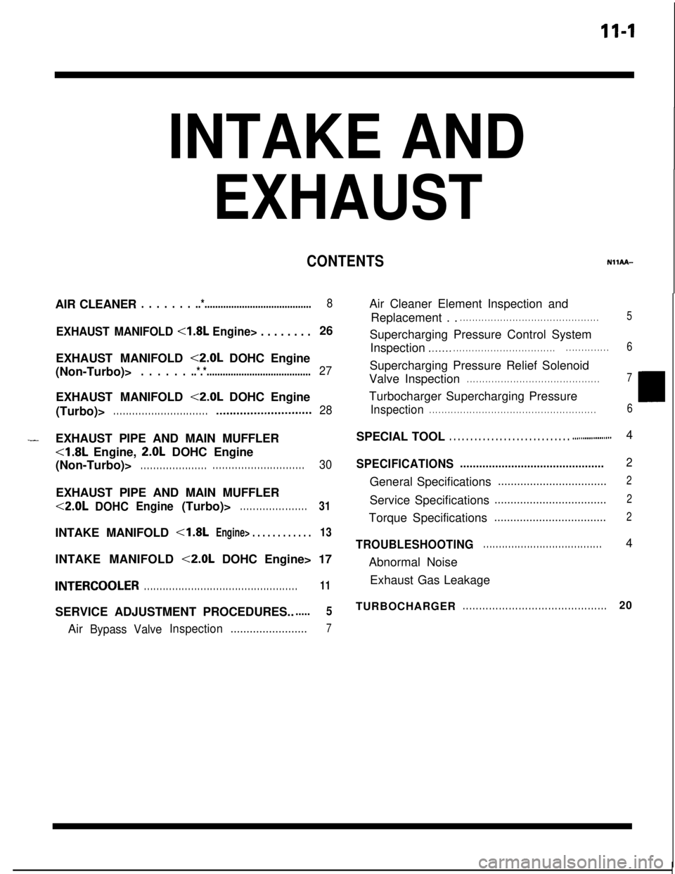
11-l
INTAKE AND
EXHAUSTAIR CLEANER
. . . . . . . ..*........................................8
EXHAUST MANIFOLD <1.8L Engine> . . . . . . . .26
EXHAUST MANIFOLD
<2.0L DOHC Engine
(Non-Turbo)>
. . . . . . ..*.*.......................................27EXHAUST MANIFOLD
<2.0L DOHC Engine
(Turbo)>
. . . . . . . . . . . . . . . . . . . . . . . . . . . . . .*...........................28
CONTENTSNllAA--
-EXHAUST PIPE AND MAIN MUFFLER<1.8L Engine,
2.0L DOHC Engine
(Non-Turbo)>
. . . . . . . . . . . . . . . . . . . . .. . . . . . . . . . . . . . . . . . . . . . . . . . . . .30EXHAUST PIPE AND MAIN MUFFLER<2.0L
DOHCEngine(Turbo)>. . . . . . . . . . . . . . . . . . . . .31INTAKE MANIFOLD
<1.8LEngine> . . . . . . . . . . . .13INTAKE MANIFOLD
<2.0L DOHC Engine> 17
INTERCOOLER. . . . . . . . . . . . . . . . . . . . . . . . . . . . . . . . . . . . . . . . . . . . . . . . .11SERVICE ADJUSTMENT PROCEDURES..
.....5Air
Bypass ValveInspection........................7Air Cleaner Element Inspection and
Replacement . .
. . . . . . . . . . . . . . . . . . . . . . . . . . . . . . . . . . . . . . . . . . . . .5Supercharging Pressure Control System
Inspection
.,...... . . . . . . . . . . . . . . . . . . . . . . . . . . . . . . . .. . . . . . . . . . . . . .6Supercharging Pressure Relief Solenoid
Valve Inspection
. . . . . . . . . . . . . . . . . . . . . . . . . . . . . . . . . . . . . . . . . . .7Turbocharger Supercharging Pressure
Inspection. . . . . . . . . . . . . . . . . . . . . . . . . . . . . . . . . . . . . . . . . . . . . . . . . . . . . .6SPECIAL TOOL
. . . . . . . . . . . . . . . . . . . . . . . . . . . . . ..#................4
SPECIFICATIONS.............................................2General Specifications
..................................2Service Specifications
...................................2Torque Specifications
...................................2
TROUBLESHOOTING. . . . . . . . . . . . . . . . . . . . . . . . . . . . . . . . . . . . . .4
Abnormal Noise
Exhaust Gas Leakage
TURBOCHARGER
. . . . . . . . . . . . . . . . . . . . . . . . . . . . . . . . . . . . . . . . . . . .20
Page 424 of 1216

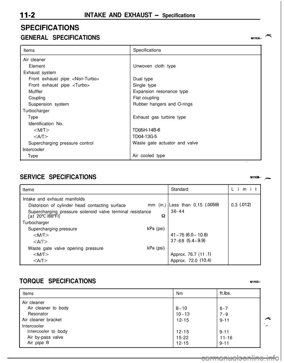
11-2INTAKE AND EXHAUST - Specifications
SPECIFICATIONS
GENERAL SPECIFICATIONS.prtNIICA-Items
Air cleaner
ElementExhaust system
Front exhaust pipe
Front exhaust pipe
Muffler
CouplingSuspension system
Turbocharger
TypeIdentification No.
4iT>Supercharging pressure control
Intercooler
TypeSpecifications
Unwoven cloth type
Dual type
Single type
Expansion resonance type
Flat coupling
Rubber hangers and O-rings
Exhaust gas turbine type
TD05H-14B-6
TD04-13G-5Waste gate actuator and valve
Air cooled type
SERVICE SPECIFICATIONSNllCB- spr*
ItemsStandardIntake and exhaust manifolds
Distorsion of cylinder head contacting surfacemm (in.) Less than 0.15
(.0059)Supercharging pressure solenoid valve terminal resistance36-44
[at
20°C (68”F)lQ
TurbochargerSupercharging pressure
kPa (psi)
kPa (psi)
0.3
l.0121
TORQUE SPECIFICATIONSNllCC-
ItemsAir cleaner
Air cleaner to body
ResonatorAir cleaner bracket
Intercooler
Intercooler to body
Air by-pass valve
Air pipe
B
Nmftlbs.
8-106-7
10-137-9
12-15
9-11
12-15
9-11
15-22
11-16
12-15
9-11
Page 455 of 1216

14-IFUEL SYSTEM
CONTENTS
AUTO-CRUISECONTROLSYSTEM...........................................109AUTO-CRUISECONTROL.......................................................140SERVICEADJUSTMENTPROCEDURES..............................135Accelerator Cable, Throttle Cable and Auto-cruise
ControlCableInspectionandAdjustment........................136Auto-cruise
ControlSystemInspection.............................135lndrvrdualPartsInspection..................................................137SPECIFICATIONS.....................................................................109GeneralSpecifications.......................................................109ServiceSpecifications
.........................................................109Torque Specrfications..........................................................109TROUBLESHOOTING...............................................................110Auto-CruiseControlCircurt................................................128Auto-cruise
ControlComponentsLocation........................126Auto-cruise Control Related Harnesses
.............................125Check Chart
........................................................................114Input Check.........................................................................123Self-diagnosis
Check..........................................................121Troubleshootrng
Quick-referenceChart..............................110ENGINECONTROL.......................................................................105ENGINECONTROL..................................................................107--SERVICEADJUSTMENTPROCEDURES..............................106Accelerator Cable Inspection and Adjustment..................106Accelerator Switch Inspectron and Adjustment................106SPECIFICATIONS.....................................................................105Lubricants.............................................................................105Sealant.................................................................................105ServiceSpecifications
..........................................................105TorqueSpecifications..........................................................105TROUBLESHOOTING...............................................................105FUELSYSTEM..............................................................................2FUELFILTER............................................................................104FUELLINEANDVAPORLINE..............................................102FUEL PUMP, FUEL GAUGE UNIT ANDOVERFILL LIMITER(TWO-WAY VALVE)
Switch........................................................64Air Conditioner Power Relay
..............................................67Components
Location......................................................56
ControlRelay
.................................................................66EGRControlSolenoidValve...............................................67EGRTemperatureSensor..................................................64Engine Coolant Temperature Sensor
.................................62IdlePosrtionSwitch
...........................................................63IdleSpeedControlServo
.............................
....................65InhibitorSwitch....................................................................65hjeCtOrS................................................................................65IntakeAirTemperatureSensor..........................................6’2MalfunctionlndtcatorLight
..........................................58MotorPosition
Sensor................................................63OxygenSensor
.................................................................64Power Steering 011 Pressure Swatch...........................65PowerTransistor
................................................................67PurgeControlSolenoidValve.........................................67
Self-Diagnosis.......................................................................
ThrottlePositronSensor.....................................................
Vehicle Speed Sensor.........................................................MPI
SYSTEMINSPECTION<2.0L DOHCEngine>...........Air Conditioner Power Relay..............................................
Arr Conditioner Swatch........................................................
Components Location
.........................................................
Control
Relay.......................................................................
EGR Control Solenoid Valve...............................................
EGR Temperature Sensor
...................................................
Engine Coolant Temperature Sensor
.................................Fuel Pressure Control Valve...............................................
Idle Position Switch
............................................................
Idle
SpeedControlServo...................................................Injectors
................................................................................
Intake Air Temperature Sensor..........................................
Malfunction Indicator Light.................................................
Oxygen Sensor
....................................................................
Power
Steering
OilPressureSwitch.................................Power Transistor
.................................................................
Purge Control Solenoid Valve.............................................
Self-Diaanosis.......................................................................
58
63
2382
79
688182
79
7682
77
79
79
76
727879
82
8273ThrottletiPosition Sensor
.....................................................77Vehicle Speed Sensor
.........................................................79SERVICE ADJUSTMENT PROCEDURES<1.8L Engine>........................................................................41Curb Idle Speed Inspection
................................................41EGR Valve Control Vacuum Check....................................47Fuel Pressure Test
..............................................................44Fuel Pump Operation Check
..............................................44Idle Speed Control and Throttle Position
Sensor Adjustment
..............................................................
41Purge Port Vacuum Check
.................................................47Release of Residual Pressure from
High Pressure Fuel Hose
...................................................
44Throttle
Body(Throttle Valve Area)Cleaning....................43SERVICE ADJUSTMENT PROCEDURES<2.0LDOHCEngine>............................................................48Basic Idle Speed Adjustment
.............................................
48
Curb Idle Speed Inspection
................................................48EGR Valve Control Vacuum Check....................................55Fuel Pressure Test
..............................................................52Fuel Pump Operation Check
..............................................51Idle Position Switch Adjustment........................................52Purge Port Vacuum Check
.................................................55Release of Residual Pressure from
High Pressure Fuel Hose
...................................................51Throttle Body (Throttle Valve Area) Cleaning....................51ThrottlePositionSensorAdjustment.................................50SPECIALTOOLS......................................................................6SPECIFICATIONS.....................................................................2GeneralSpecifications.........................................................2Sealant and Adhesive
.........................................................5Service Specifications
..........................................................4Torque Specifications
..........................................................5THROlTLEBODY<1.8LEngine>........................................85THROlTLE BODY <2.0L DOHC Engine>............................89TROUBLESHOOTING...............................................................6
Page 459 of 1216

FUEL SYSTEM - SDecifications14-5
-.
Items
Injector coil resistance52
Specifications
13-I 6 [at 20°C (68”F)j
2-3 [at 20°C (68”F)I
TORQUE SPECIFICATIONSN14CC-A
,,-
ItemsINm1 ft.lbs.
Center cover
Oxygen sensor
Engine coolant temperature sensor
Throttle position sensor attaching screws
Idle speed control servo attaching screws <2.0L DOHC Engine>
Delivery pipe mounting bolts
High-pressure fuel hose to delivery pipe
Fuel pressure regulator to delivery pipe
<1.8L Engine>
<2.0L DOHC Engine>
Accelerator cable clamp
Throttle body mounting bolts and nuts
Throttle body stay mounting nut
4ccelerator cable adjusting bolts
Lateral rod attaching bolt
Self-locking nut
Fuel tank drain plug
Electrical fuel pump
Screws
Bolt (at lower side)Gel
gauge unit mounting screws
-ligh pressure hose to electrical fuel pump
iigh pressure hose to fuel main pipe
3attery tray to battery
3attery tray mounting boltGel
main pipe to fuel filter
Zye boltGel filter
mounting bolts
%el pipes clip attaching bolt
Japor pipe assembly mounting bolt
Ianister holder mounting bolt
2.5-3.5
40-50
20-40
1.5-2.5
2.5-4.5
IO-13
4-6
7-l 15-8
8-106-7
IO-137-9
15-2211-16
15-2211-16
4-63-4
80-l 0057-72
21-3115-22
15-2011-14
2-3
9-14
2-3
30-40
30-40
2-3
9-14
30-40
25-35
9-14
9-14
9-14
9-14
2-3
30-36
15-29
1.1-1.8
1.8-3.3
7-9
3-4
1.4-2.2
6.5-10
1.4-2.2
22-29
22-29
1.5-2
7-14
22-29
18-25
7-10
7-10
7-10
7-10
SEALANT AND ADHESIVENMCE-A
Items
Engine coolant temperature sensor threaded portion
Fuel tank hole cover
Specified sealant
MOPAR Part No.4318034 or equivalent
MOPAR Rope Caulk Sealer 3/l 6 x 80” roll Part No.4026044 or equivalent
Page 517 of 1216

FUEL SYSTEM - MPI Svstem Inspection <1.8L Engine>18-63
Throttle position sensor
Groundoutput
Sensorpower
SUPPlY(5V)
1 FUO507
6FU1244Motor
Dosition sensor connector
(motor ‘side, front view)
T
6FU1247Motor position sensor
connector(motor side, front view)
6FU1252
THROITLE POSITION SENSOR
INSPECTION
Nl4OBBKa(1) Disconnect the throttle position sensor connector.
(2) Measure resistance between terminal
@I (sensor ground)
and terminal
@ (sensor power).
Standard value: 3.5-6.5
kGI(3) Connect a pointer type ohmmeter between terminal
@(sensor ground) and terminal
@ (sensor output).
(4) Operate the throttle valve slowly from the idle position to
the full open position and check that the resistance changessmoothly in proportion with the throttle valve opening
angle.(5) If the resistance is out of specification, or fails to change
smoothly, replace the throttle position sensor.
Throttle position sensor installation torque:
1.5
- 2.5 Nm (1.1 - 1.6 ftlbs.)
IDLE POSITION SWITCH
INSPECTION
N14QKADa(1) Disconnect the connectors of the motor position sensor.
(2) Check the continuity between terminal
@ and the body
ground.
IAccelerator pedalIContinuityI
DepressedINon-conductive (@J fl)I
ReleasedIConductive (0 fl)I(3) If defective, replace the idle speed control servo assembly.
MOTOR POSITION SENSOR
INSPECTION
N140lAJ(1) Disconnect the motor position sensor connector.
(2) Measure the resistance between terminals
@ and 0.Standard value: 4
- 6 kfi
Page 531 of 1216

FUEL SYSTEM - MPI Svstem InsDection <2.0L DOHC Engine>14-77INSTALLATION
(1) Apply specified sealant to threaded portion and tighten to
specified torque.
Specified sealant: MOPAR Part No.4318034 or
equivalent
Specified torque: 20
- 40 Nm (15 - 29 ft.lbs.1(2) Fasten harness connectors securely.
THROTTLE POSITION SENSOR
INSPECTION
N14QBBKl(1) Disconnect the throttle position sensor connector.
(2) Measure resistance between terminal
@I (sensor ground)
and terminal
@ (sensor power).
Standard value: 3.5
- 6.5 kR(3) Connect a pointer type ohmmeter between terminal
@I(sensor ground) and terminal
@ (sensor output).
(4) Operate the throttle valve slowly from the idle position to
the full open position and check that the resistance changessmoothly in proportion with the throttle valve opening
angle.
6FU1244(5) If the resistance is out of specification, or fails to change
smoothly, replace the throttle position sensor.
Throttle position sensor installation torque:
1.5
- 2.5 Nm (1.1 - 1.8 ft.lbs.)
J II\/ hFU1419IDLE POSITION SWITCH
INSPECTION
N14QKAEa(1) Keeping the acceleration pedal released, check that the
throttle valve lever or the idle position switch is pushed.
NOTEIf it is not pushed, adjust the idle position switch (fixed
speed adjusting screw). (Refer to
P.14-52.)(2) Disconnect the idle position switch connector.
(3) Check the continuity between terminal
@) to the ground.
Page 559 of 1216

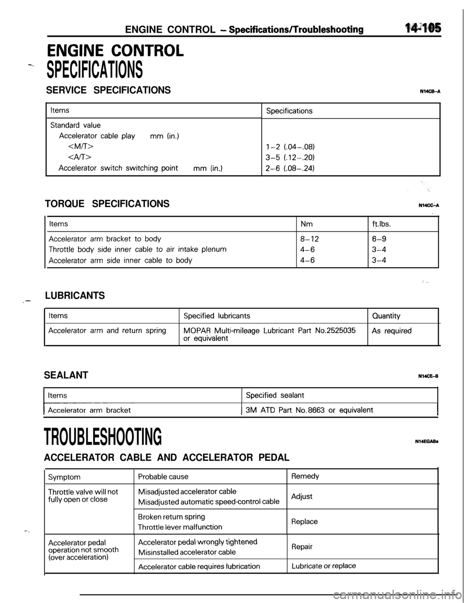
ENGINE CONTROL - SpecificatiodTroubleshooting
ENGINE CONTROL
-.
SPECIFICATIONS
SERVICE SPECIFICATIONSN14CEA
Items
Standard value
Accelerator cable playmm (in.)
dfi>
Accelerator switch switching pointmm (in.)Specifications
1-2 (.04-.08)
3-5 (.12-.20)
2-6 (.08-.24)
N14CkATORQUE SPECIFICATIONS
Items
Accelerator arm bracket to body
Throttle body side inner cable to air intake plenum
Accelerator arm side inner cable to body
Nmft.lbs.
8-126-9
4-63-4
4-63-4
I
: j,
LUBRICANTS_-
Items
Accelerator arm and return spring
Specified lubricants
MOPAR Multi-mileage Lubricant Part No.2525035
or equivalentQuantityAs required
SEALANTN14CE.-BItems
I-- ~Accelerator arm bracket
Specified sealant
I3M ATD Part No.8663 or equivalentI
-.
TROUBLESHOOTINGN14EGABa
ACCELERATOR CABLE AND ACCELERATOR PEDAL
Symptom
Throttle valve will notfully
open or close
Probable causeRemedyMisadjusted
accelerator cableMisadjusted automatic
speed-control cableAdjust
Broken return springThrottle
lever malfunctionReplace
Accelerator pedaloperation not smooth(over acceleration)
Accelerator pedal wrongly tightenedMisinstalled
accelerator cable
Accelerator cable requires lubrication
Repair
Lubricate or replace