1991 MITSUBISHI ECLIPSE service
[x] Cancel search: servicePage 896 of 1216

21-202AUTOMATIC TRANSAXLE - Troubleshooting
CONVERTER STALL TESTStall test consist of determining maximum engine
speed obtained at full throttle in “D” and “R”
positions. This test checks torque converter stator
overrunning clutch operation, and holding ability of
transaxle clutches and low-reserve brake.
CautionDuring this test, make sure that no one stand in
front of or behind vehicle.
1. Check transaxle fluid level. Fluid should be at
normal operating temperature
[70-80°C (160-
18O”F)]. Engine coolant should also be at normaloperating temperature
[80-90°C (180- 19O”F)l.2. Apply chocks to both rear wheels.
3. Attach engine tachometer.
4. Apply parking and service brakes fully.
5. Start engine.
6. With selector lever in “D” position, depress
accelerator pedal fully to read engine maximum
rpm. Do not hold throttle wide open any longer
than is necessary to obtain maximum engine
rpm reading, and never longer than 5 seconds ata time. If more than one stall test is required,
operate engine at approximatey 1,000 rpm in
neutral for 2 minutes to cool transaxle fluid
between tests.
Stall speed:
1,800-3,200 rpm
TRANSAXLE CONTROL7. Place selector lever to “R” position and perform
?+stall test by the same procedure as in foregoing
-,
item.Stall Speed Above Specification in “D”
If stall speed is higher than specification, rear clutchor overrunning clutch of transaxle is slipping. In this
case, perform hydraulic test to locate cause of
slippage.Stall Speed Above Specifjcation in “R”
If stall speed is higher than specification, front
clutch of transaxle or low-reverse brake is slipping.
In this case, perform hydraulic test to locate cause
of slippage.
Stall Speed Below Specification in “D” and “R”
If stall speed is lower than specification, insufficient
engine output or faulty torque converter is sus-
pected. Check for engine misfiring, ignition timing,
valve clearance etc. If these are good, torque
converter is faulty.
Symptom
Selector lever operation isstiff
Probable causeIncorrect adjustment of sleeve
Incorrect adjustment of control cable
Excessive wear of detent plate
Worn contact surfaces of pushbutton and sleeveRemedyAdjust
Replace
Starter motor does notoperate with the selector
lever in the “N” or
“P”position
Will not shift to
4-speedMalfunction in inhibitor switch
Malfunction of starter relay
Incorrect adjustment of control cableMalfunction of OD switch
Replace
Adjust
Replace
Page 903 of 1216

AUTOMATIC TRANSAXLE - service Adjustment Procedures21-209
09Pooi awith this range.
09POOll
TWO382
SERVICE ADJUSTMENT PROCEDURESN21FB6E
TRANSAXLE FLUID LEVEL INSPECTION1. Drive until the fluid temperature reaches the usual tem-
perature
[70-80°C (160- 18O”F)I.2. Place vehicle on level floor.
3. Move selector lever sequentially to every position to fill
torque converter and hydraulic circuit with fluid, then place
lever in “N” Neutral position.
4. Before removing dipstick, wipe all dirt from area around
dipstick. Then take out the dipstick and check the conditionof the fluid.
The transaxle should be overhauled under the following
conditions.l If there is a “burning” odor.
l If the fluid color has become noticeably blacker.
lIf there is a noticeably great amount of metal particles inthe fluid.
5.Check to see if fluid level is in “HOT” range on dipstick. If
fluid level is low, add automatic transaxle fluid until level
reaches “HOT” range.
Transaxle fluid: MOPAR ATF PLUS (Automatic trans-
mission fluid type 7176) or Dia ATF SPor equivalent
Low fluid level can cause a variety of conditions
becaljse it
allows pump to take in air along with fluid. Air trapped in
hydraulic circuit forms bubbles which make fluid spongy.
Therefore, pressures will be erratic, causing delayed shift,
slippy clutch and brakes, etc.
Improper filling can also raise fluid level too high. When
transaxle has too much fluid, gears churn up foam and
cause the same conditions which occur with low fluid level,
resulting in accelerated deterioration of automatic transaxle
fluid.In either case, air bubbles can cause overheating, fluid
oxidation, which can interfere with normal valve, clutch,
and servo operation.Foaming can also result in fluid
escaping from transaxle vent where it may be mistaken for
a leak.6. Be sure to examine fluid on dipstick closely.
TRANSAXLE FLUID REPLACEMENTN21FCBAaRefer to GROUP O-Maintenance Service.
TRANSFER OIL LEVEL INSPECTIONNZlFXAATransfer oil level inspection is the same as for the manual
transaxle transfer.
Refer to GROUP
22-Service Adjustment Procedures.
TRANSFER OIL REPLACEMENTNZlFYAFaTransfer oil replacement is the same as for manual transaxle
transfer.Refer to GROUP
22-Service Adjustment Procedures.
Page 904 of 1216

21-210AUTOMATIC TRANSAXLE - Service Adjustment Procedures
OSA0141
ti Button pressed (while brake
pedal is depressed)
l Button not pressed
9 Button pressed
SELECTOR LEVER OPERATlON CHECKNZlFlAE1. Shift selector lever to each range and check that lever
+moves smoothly and is controled. Check that position
indicator is correct.
-L*
2.Check to be sure the selector lever can be shifted to each
position (by button operation as shown in the illustration).
3. Start the engine and check if the vehicle moves forward
when the selector lever is shifted from
N to D, and moves
backward when shifted to
R.4. When the shift lever malfunctions, adjust control cable
and selector lever sleeve. Check for worn shift lever
assembly sliding parts.
NOTETo move the selector lever from the “P” position to any
other position, first turn the ignition key to any position
other than “LOCK (OFF)” and depress the brake pedal.
KEY INTERLOCK MECHANISM CHECKNZlFUAA1. Completely stop the vehicle and switch OFF the engine
before making the check.
2. Check to be sure that, under the following conditions, the
select lever cannot be moved from the “P” position to any
?cother position.
~.‘,Also check, at the same time, that the button cannot be
pressed.Ignition key position:
“LOCK (OFF)“, or removed
Brake pedal: Depressed
3.Check to be sure that, under the following conditions, the
select lever can be moved from the “P” position to any
other position.
Press the button a few times and check to be sure that the
select lever moves smoothly.
Ignition key position: “ACC”
Brake pedal : Depressed
Button
: Pressed4. Check to be sure that, at all positions of the select lever
(other than
“P”), the ignition key cannot be turned to the
“LOCK (OFF)” position.
Check to be sure that the ignition key smoothly turns to the“LOCK (OFF)” position when the select lever is then set to
the “P” position and the button is released.
5. If a malfunction is discovered when following the above
,”checking procedures, either adjust or check the key
interlock cable mechanism. (Refer to
P.21-220.)
Page 905 of 1216
AUTOMATIC TRANSAXLE - Service Adjustment Procedures21-21109A0146
OQMOO45
control lever
control lever
5 mm
Section A-A
(2 in.)Manual
controllever
Switch body
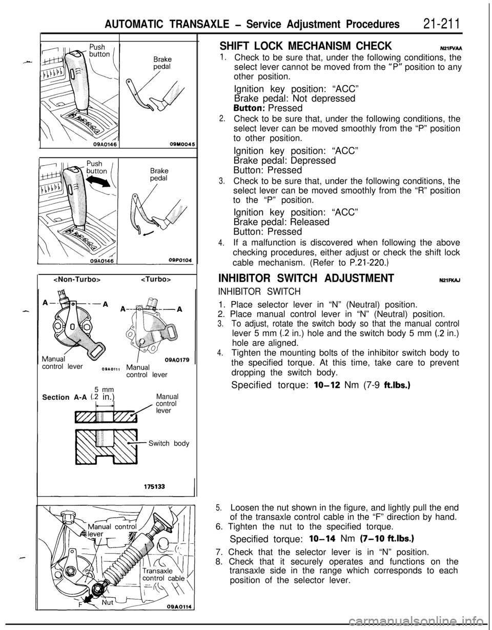
SHIFT LOCK MECHANISM CHECKN21FVAA
1.
2.
3.
4.Check to be sure that, under the following conditions, the
select lever cannot be moved from the
“P” position to any
other position.
Ignition key position: “ACC”
Brake pedal: Not depressedButton: Pressed
Check to be sure that, under the following conditions, the
select lever can be moved smoothly from the “P” position
to other position.
Ignition key position: “ACC”
Brake pedal: Depressed
Button: Pressed
Check to be sure that, under the following conditions, the
select lever can be moved smoothly from the “R” position
to the “P” position.
Ignition key position: “ACC”
Brake pedal: Released
Button: Pressed
If a malfunction is discovered when following the above
checking procedures, either adjust or check the shift lock
cable mechanism. (Refer to
P.21-220.)
INHIBITOR SWITCH ADJUSTMENTNZlFKAJ
INHIBITOR SWITCH1. Place selector lever in “N” (Neutral) position.
2. Place manual control lever in “N” (Neutral) position.
3.To adjust, rotate the switch body so that the manual controllever 5 mm
(2 in.) hole and the switch body 5 mm (.2 in.)
hole are aligned.
4.Tighten the mounting bolts of the inhibitor switch body to
the specified torque. At this time, take care to prevent
dropping the switch body.
Specified torque:
lo-12 Nm (7-9 ftlbs.)
5.Loosen the nut shown in the figure, and lightly pull the end
of the transaxle control cable in the “F” direction by hand.
6. Tighten the nut to the specified torque.
Specified torque:
IO-14 Nm (7-10 ftlbs.)7. Check that the selector lever is in “N” position.
8. Check that it securely operates and functions on the
transaxle side in the range which corresponds to each
position of the selector lever.
Page 906 of 1216
21-212AUTOMATIC TRANSAXLE -Service Adiustment Procedures
1750464
KICKOOWN SERVO ADJUSTMENTNZlFRAB1. Completely remove all dirt and other materials adhered
G+around the kickdown servo switch.
-i-s-2. Remove the snap ring.
3. Remove the kickdown servo switch.
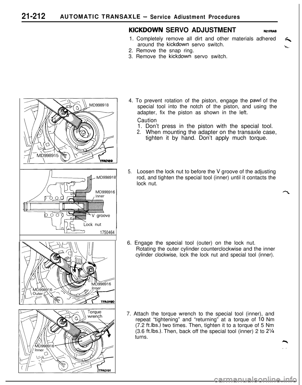
4. To prevent rotation of the piston, engage the
pawl of the
special tool into the notch of the piston, and using the
adapter, fix the piston as shown in the left.
Caution1. Don’t press in the piston with the special tool.
2.When mounting the adapter on the transaxle case,
tighten it by hand. Don’t apply much torque.
5.Loosen the lock nut to before the V groove of the adjusting
rod, and tighten the special tool (inner) until it contacts the
lock nut.
6. Engage the special tool (outer) on the lock nut.
Rotating the outer cylinder counterclockwise and the inner
cylinder clockwise, lock the lock nut and special tool (inner).7. Attach the torque wrench to the special tool (inner), and
repeat “tightening” and “returning” at a torque of
IO Nm
(7.2
ft.lbs.) two times. Then, tighten it to a torque of 5 Nm
(3.6
ftlbs.). Then, back off the special tool (inner) 2 to 2%
turns.*
. .
Page 907 of 1216
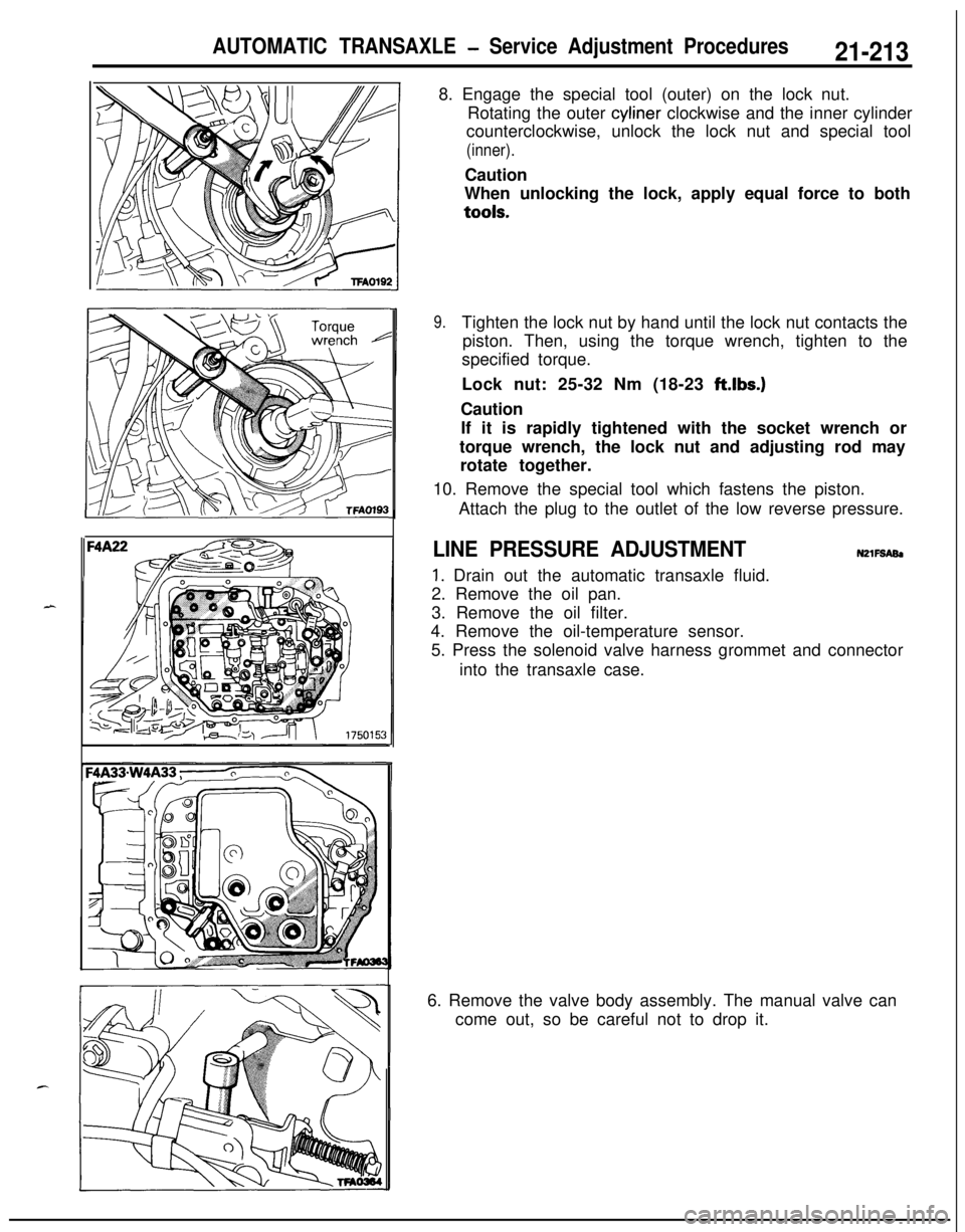
AUTOMATIC TRANSAXLE - Service Adjustment Procedures21-2138. Engage the special tool (outer) on the lock nut.
Rotating the outer cyliner clockwise and the inner cylinder
counterclockwise, unlock the lock nut and special tool
(inner).Caution
When unlocking the lock, apply equal force to bothtools.
9.Tighten the lock nut by hand until the lock nut contacts the
piston. Then, using the torque wrench, tighten to the
specified torque.
Lock nut: 25-32 Nm (18-23 ft.lbs.)
Caution
If it is rapidly tightened with the socket wrench or
torque wrench, the lock nut and adjusting rod may
rotate together.
10. Remove the special tool which fastens the piston.
Attach the plug to the outlet of the low reverse pressure.
LINE PRESSURE ADJUSTMENTN2lFSABl
1. Drain out the automatic transaxle fluid.
2. Remove the oil pan.
3. Remove the oil filter.
4. Remove the oil-temperature sensor.
5. Press the solenoid valve harness grommet and connector
into the transaxle case.
6. Remove the valve body assembly. The manual valve can
come out, so be careful not to drop it.
Page 908 of 1216
21-214AUTOMATIC TRANSAXLE - Service Adjustment Procedures
'50157
F4
1
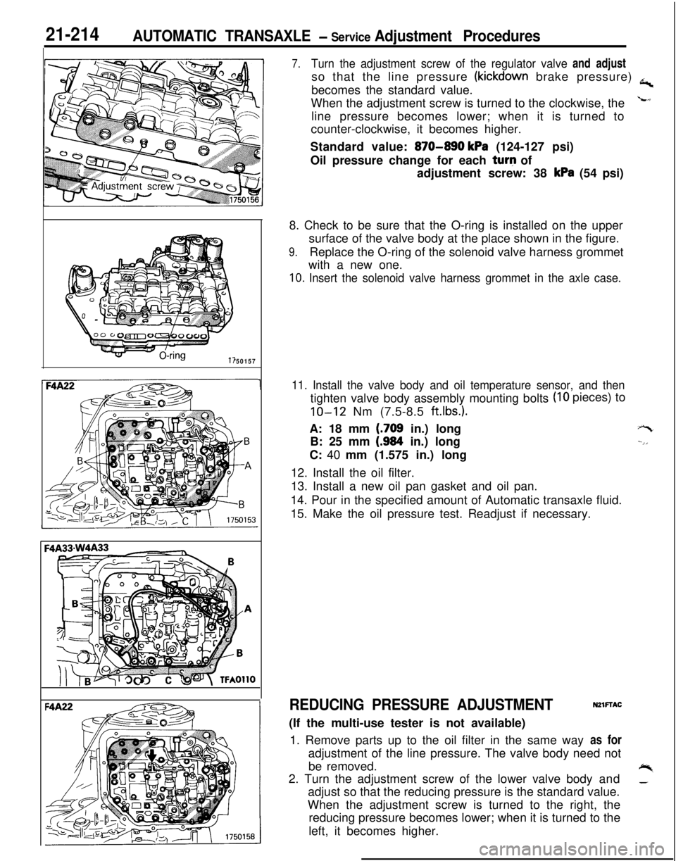
7.Turn the adjustment screw of the regulator valve and adjustso that the line pressure
(kickdown brake pressure) a,becomes the standard value.
When the adjustment screw is turned to the clockwise, the
Lline pressure becomes lower; when it is turned to
counter-clockwise, it becomes higher.
Standard value:
870-890 kPa (124-127 psi)
Oil pressure change for each turq of
adjustment screw: 38
kPa (54 psi)
8. Check to be sure that the O-ring is installed on the upper
surface of the valve body at the place shown in the figure.
9.Replace the O-ring of the solenoid valve harness grommet
with a new one.
10. Insert the solenoid valve harness grommet in the axle case.
11. Install the valve body and oil temperature sensor, and then
(IO pieces) to
tighten valve body assembly mounting bolts
IO-12 Nm (7.5-8.5 ft.lbs.).A: 18 mm
(.709 in.) long
B: 25 mm
(.984 in.) long
C: 40 mm (1.575 in.) long
12. Install the oil filter.
13. Install a new oil pan gasket and oil pan.
14. Pour in the specified amount of Automatic transaxle fluid.
15. Make the oil pressure test. Readjust if necessary.
+-t
--,,
REDUCING PRESSURE ADJUSTMENTNZlFTAC(If the multi-use tester is not available)
1. Remove parts up to the oil filter in the same way as for
adjustment of the line pressure. The valve body need not
be removed.
+%2. Turn the adjustment screw of the lower valve body and_adjust so that the reducing pressure is the standard value.
When the adjustment screw is turned to the right, the
reducing pressure becomes lower; when it is turned to the
left, it becomes higher.
Page 909 of 1216
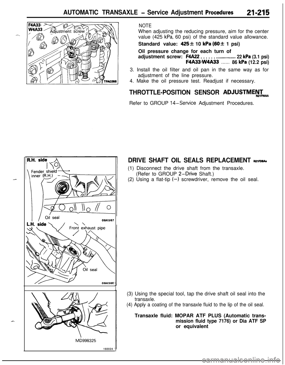
AUTOMATIC TRANSAXLE - Service Adjustment Piocedures21-215
NOTEWhen adjusting the reducing pressure, aim for the center
value (425
kPa, 60 psi) of the standard value allowance.
Standard value:
425+ 10 kPa (60+ 1 psi)
Oil pressure change for each turn of
adjustment screw:
F4A22 . . . . . . ;...........,.. 22 kPa (3.1 psi)
F4A33mW4A33. . . . . .86 kPa (12.2 psi)3. Install the oil filter and oil pan in the same way as for
adjustment of the line pressure.
4. Make the oil pressure test. Readjust if necessary.
OQK567
OSKS68
Mb998325
160024
THROTTLE-POSITION SENSOR ADJUSTMEN&
Refer to GROUP
14-Service Adjustment Procedures.
DRIVE SHAFT OIL SEALS REPLACEMENT NZWWA,(1) Disconnect the drive shaft from the transaxle.
(Refer to GROUP
2-Drive Shaft.)
(2) Using a flat-tip
(-) screwdriver, remove the oil seal.
(3) Using the special tool, tap the drive shaft oil seal into the
transaxle.
(4) Apply a coating of the transaxle fluid to the lip of the oil seal.Transaxle fluid: MOPAR ATF PLUS (Automatic trans-
mission fluid type 7176) or Dia ATF SPor equivalent