Page 919 of 1216

AUTOMATIC TRANSAXLE - Transaxle Assembly 21"225
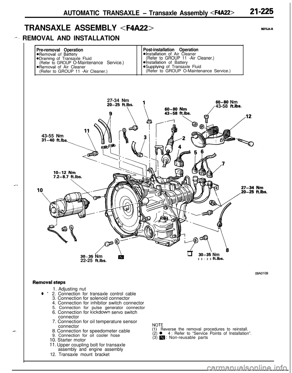
TRANSAXLE ASSEMBLY N2ll.A.A
,--. REMOVAL AND INSTALLATION
Pre-removal OperationPost-installation Operation@Removal of Battew@Installation of Air CleaneraDraining of Transaxle Fluid(Refer to GROUP 11 -Air Cleaner.)(Refer to GROUP O-Maintenance Service.)@Installation of BatteryaRemoval of Air Cleaner*Supplying of Transaxle Fluid
(Refer to GROUP 11 -Air Cleaner.)(Refer to GROUP O-Maintenance Service.)
27-34 Nm20-25
ftlbs.
1143-55 Nm31-40
ft.lbs.-\60-80
flrn60-80 Nm/43-58 ft.lbs.
//\-LTT \.30-35 Nm
AIq 30-35 Nm22-25 klbs.22-25 ft.lbs.
09A0109
Removal steps1. Adjusting nut
l *2. Connection for transaxle control cable3. Connection for solenoid connector
4. Connection for inhibitor switch connector
5. Connection for pulse generator connector
6. Connection for kickdown servo switch
connector
7. Connection for oil temperature sensor
connector
8. Connection for speedometer cable
9. Connection for oil cooler hose
10. Starter motor
11. Upper coupling bolt for transaxleassembly and engine assembly
12. Transaxle mount bracket
$?everse the removal procedures to reinstall.
(2) l 4 : Refer to “Service Points of Installation”.
(3) m : Non-reusable parts
Page 920 of 1216
21-226AUTOMATIC TRANSAXLE - Transaxle Assembly 46-53 Nm
33-38
ftlbs.30-35 Nm
22-25
ftlbs.IO-12 Nm
7-9 ftlbs.
7-10 ft.lbs.
I18m
16
13. Under guard14. Cotter pins
15. Connection for tie rod end
16. Connection for lower arm ball joint17. Connection for drive shaft
18.
Circlip19. Bell housing cover
20. Special bolts
21. Lower coupling bolt for transaxle
assembly and engine assembly
22. Transaxle assembly
NOTE(1) Reverse the removal procedures to reinstall.
(2) l *
: Refer to “Service Points of Removal”.
(3) m : Non-reusable parts
Page 921 of 1216

AUTOMATIC TRANSAXLE - Transaxle Assemblv
-MB991 11312K513Pry bar
*Transaxle
llK611
SERVICE POINTS OF REMOVALN2llEAK
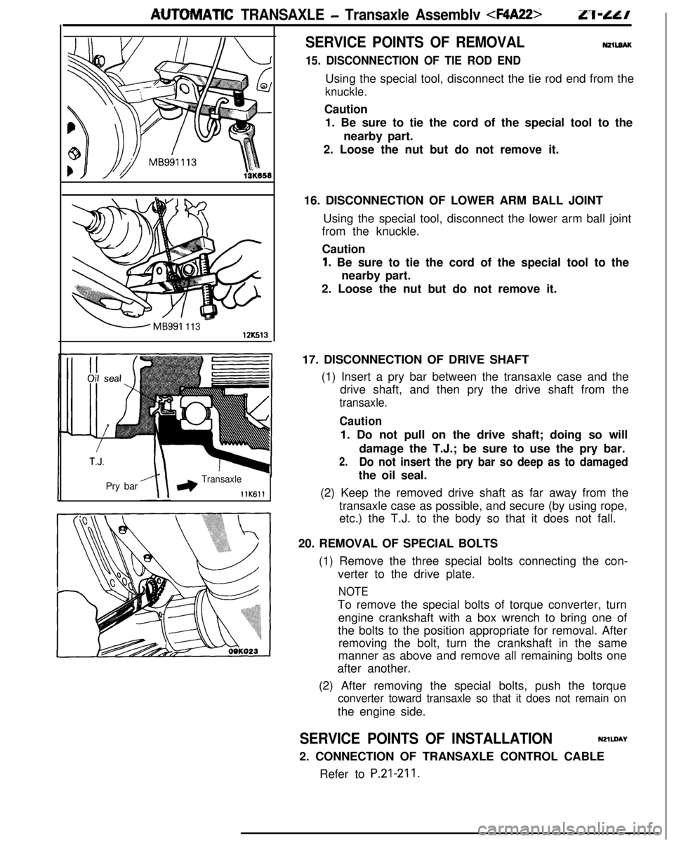
15. DISCONNECTION OF TIE ROD ENDUsing the special tool, disconnect the tie rod end from the
knuckle.Caution
1. Be sure to tie the cord of the special tool to the
nearby part.
2. Loose the nut but do not remove it.
16. DISCONNECTION OF LOWER ARM BALL JOINT
Using the special tool, disconnect the lower arm ball joint
from the knuckle.
Caution
1. Be sure to tie the cord of the special tool to the
nearby part.
2. Loose the nut but do not remove it.
17. DISCONNECTION OF DRIVE SHAFT
(1) Insert a pry bar between the transaxle case and the
drive shaft, and then pry the drive shaft from the
transaxle.
Caution1. Do not pull on the drive shaft; doing so will
damage the T.J.; be sure to use the pry bar.
2.Do not insert the pry bar so deep as to damagedthe oil seal.
(2) Keep the removed drive shaft as far away from the
transaxle case as possible, and secure (by using rope,
etc.) the T.J. to the body so that it does not fall.
20. REMOVAL OF SPECIAL BOLTS
(1) Remove the three special bolts connecting the con-
verter to the drive plate.
NOTETo remove the special bolts of torque converter, turn
engine crankshaft with a box wrench to bring one of
the bolts to the position appropriate for removal. After
removing the bolt, turn the crankshaft in the same
manner as above and remove all remaining bolts one
after another.
(2) After removing the special bolts, push the torque
converter toward transaxle so that it does not remain onthe engine side.
SERVICE POINTS OF INSTALLATIONN2lWAY
2. CONNECTION OF TRANSAXLE CONTROL CABLE
Refer to
P.21-211.
Page 953 of 1216

AUTOMATIC TRANSAXLE - Transaxle Assembly 21-259
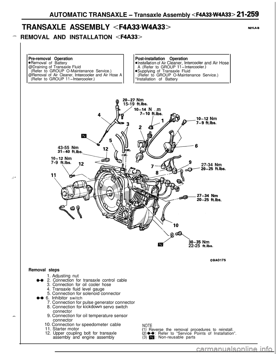
TRANSAXLE ASSEMBLY
- REMOVAL AND INSTALLATION N2ll.kB
Pre-removal OperationPost-installation Operation*Removal of Battery*Installation of Air Cleaner, Intercooler and Air Hose@Draining of Transaxle Fluid
A (Refer to GROUP II-Intercooler.)(Refer to GROUP O-Maintenance Service.)
@Removal of Air Cleaner, Intercooler and Air Hose A*Supplying of Transaxle Fluid
(Refer to GROUP O-Maintenance Service.)
(Refer to GROUP II-Intercooler.)*Installation of Battery20-27 Nm
15-19
ft.lbs.
/ IO-14 Nm
43-55 Nm31-40
ft.lbs.
lo-12 Nm
7-9 f?.lbs.
___.Ibs.
lo-12 Nm-7-9 fi.lbs.27-34 Nm20-25
ft.lbs.30-35 Nm
22-25
ft.lbs.
09A0175
Removal steps
1. Adjusting nut+42. Connection for transaxle control cable
3. Connection for oil cooler hose
4. Transaxle fluid level gauge5. Connection for solenoid connector
e+ 6. Inhibitor switch
7. Connection for pulse generator connector
8. Connection for kickdown servo switch
connector9. Connection for oil temperature sensor
connector
10. Connection for speedometer cable
11. Starter motor
12. Upper coupling bolt for transaxle
assembly and engine assembly
NOTE(1) Reverse the removal procedures to reinstall.(2) I)+ : Refer to “Service Points of Installation”.
(3) m : Non-reusable parts
Page 954 of 1216
21-260 AUTOMATIC TRANSAXLE -Transaxle Assembly 60-80 Nm
43-58
ft.lbs.60-80 Nm
43-58
ftlbs.46-53 Nm
33-38 ftlbs.30-35
22-25
/_ I/’
25
6113 Nm
DO-260 Nm144-188 ftlbs.
‘B---17-25 ftlbs.
09140176
::
t :a*
++13. Under cover
14. Connection for tie rod end
15. Connection for lower arm ball joint16. Connection for drive shaft
(R.H.)17. Connection for drive shaft (L.H.)18. Front exhaust pipe
21. Bell housing cover22. Special bolt
23. Transaxle mount bracket24. tra-rsaxle assembly lower part coupling
25. Transaxle assembly
NOTE(1) Reverse the removal procedures to reinstall.(2) 4* : Refer to “Service Points of Removal”.(3) m : Non-reusable parts
Page 955 of 1216
AUTOMATIC TRANSAXLE - Transaxle Assembly 21 kz6’1
REMOVAL AND INSTALLATION N2llA-C
(Refer to GROUP
II-Intercooler.)43-55 Nm
\i 513 \20-27 Nm
Q15-19 ft.lbs.
lo-14 NmIO-12 Nm10 ft.lbs.7-9 ftlbs.
/27-34 Nm
ft.lbs.
Y
Es.
Removal steps1. Adjusting nut
l 42. Connection for transaxle control cable3. Connection for oil cooler hose
4. Transaxle fluid level gauge5. Connection for solenoid connector
l +6. Connection for inhibitor switch connector7. Connection for pulse generator connector8. Connection for kickdown servo switch
connector9. Connection for oil temperature sensor
OQAOl63connector
10. Connection for speedometer cable11. Starter motor12. Upper coupling bolt for transaxle
assembly and engine assembly
irkeverse the removal procedures to reinstall.
(2) I)+ : Refer to “Service Points of Installation”
(3) m : Non-reusable parts
Page 956 of 1216
21-262 AUTOMATIC TRANSAXLE - Transaxle Assembly 46-53 Nm
33-38
ftlbs.
\60-80 Nm
43-58
ftlbs.60-80 Nm
43-58
ft.lbs.60-7243-52
ft.jbs. I m
124-352Nrn’m-~ ad’ 17-25- _ __
36-46 Nm
26-33
ftlbs.13. Under cover
l *
-14. Connection for tie rod end
15. Connection for lower arm ball joint16. Connection for drive shaft
(R.H.)17. Connection for drive shaft (L.H.)18. Front exhaust pipe
19. Right member and gusset
20. Transfer assembly
21. Bell housing cover
22. Special bolt
23. Transaxle mount bracket
\16
R70-80 Nm51-58
ftlbs.OOA0177
24. FoT;saxle assembly lower part coupling
25. Transaxle assembly
NOTE(1) Reverse the removal procedures to reinstall.
(2) W : Refer to “Service Points of Removal”.(3) q : Non-reusable parts
,.
Page 957 of 1216

AUTOMATR: TRANSAXLE - Transaxle Assemblv 21-263
SERVICE POINTS OF REMOVALNZlL8AU14. DISCONNECTION OF
TIE ROD END/15 LOWER ARM
BALL JOINT
Refer to
P.21-227.16. REMOVAL OF DRIVE SHAFT
(R.H.)/ 17. DRIVE SHAFT
(L.H.) Refer to
P.21-227.16. REMOVAL OF DRIVE SHAFT (R.H.)
(1) Use the suitable tool to push out the drive shaft (R.H.]from the front hub.
I1 lA0288(2) Insert a pry bar at the projection part and remove the
drive shaft
(R.H.) from the transaxle.
Caution
Do not pull out the drive shaft; doing so will
damage the T.J.; be sure to use the pry bar.
17. DISCONNECTION OF DRIVE SHAFT (L.H.)
(1) Take out the drive shaft by lightly tapping the drive shaftT.J. case with a plastic hammer.
NOTERemove the drive shaft with the hub and knuckle, etc.,
as an assembly.
Caution
1. Removing the drive shaft from the outboard
joint side can cause damage to the inboard joint.Always use a plastic hammer, etc., to remove
the drive shaft.
2. Tapping on the center bearing can damage it.
Never tap on the bearing.
(2) Keep the removed drive shaft as far away from the
transaxle case as possible, and secure (by using rope,
etc.) the joints to the body so that it does not fall.
18. REMOVAL OF FRONT EXHAUST PIPE
Refer to GROUP 1 l-Exhaust Pipe and Main Muffler.