Page 910 of 1216
21-216AUTOMATIC TRANSAXLE - Service Adjustment Procedures
I16A0905
SPEEDOMETER CABLE REPLACEMENTN21FEAK2,1. Correctly insert the adapter into the instrument panel, and
+fasten the new speedometer cable.
t,
2.Install the grommet so that, as shown in the illustration, thecable attachment is positioned upward.
Caution
1.The cable arrangement should be made so that the
radius of cable bends is 150 mm (5.9 in.) or more.
2.The arrangement of the speedometer cable should
be such that it does not interfere with other parts.
3. At the transaxle end of the speedometer cable, the key
joint should be inserted into the transaxle, and the nut
should be securely tightened.
Caution
“ccIf the cable is not correctly and securely connected, it
may cause incorrect indication by the speedometer, or
abnormal noise. Be sure to connect it correctly.
Page 911 of 1216
AUTOMATIC TRANSAXLE - Transaxle Control21-217
TRANSAXLE CONTROL
dl_i REMOVAL AND INSTALLATIONNZlub-
-.
lo-14 Nm7-10 ft.lbs.
i284-6
Nm
y-14 Nm7-10 ft.lbs.
Transaxle control cable and selector lever
assembly removal steps
1. Plug2. Side cover (B)3. Power (PWR)/Economy (ECO) switch
4. Side cover(B)
5. Cover(B)
6. Cup holder7. Carpet
8.
EZrreTstion of floor console wiring
9. Guide ring
IO. Shoulder belt 11. Floor console
17. Snap pin18. Key interlock cable (selector lever
assembly side)
23.
S$i; lock cable (selector lever assembly
26. Snap pin27. Clip
28. Adjusting nut
l 4 29. Clip++ 30. Transaxle control cable31. Selector lever assembly
zykeverse the removal procedures to reinstall.(2) l + : Refer to “Service Points of Installation”
Page 912 of 1216

2l-218AUTOMATIC TRANSAXLE - Transaxle Control
724
169-14
Nm7-10 ftlbs.7
\\4-6 Nm3-4 ft.lbs.3-4
ft.lbs.
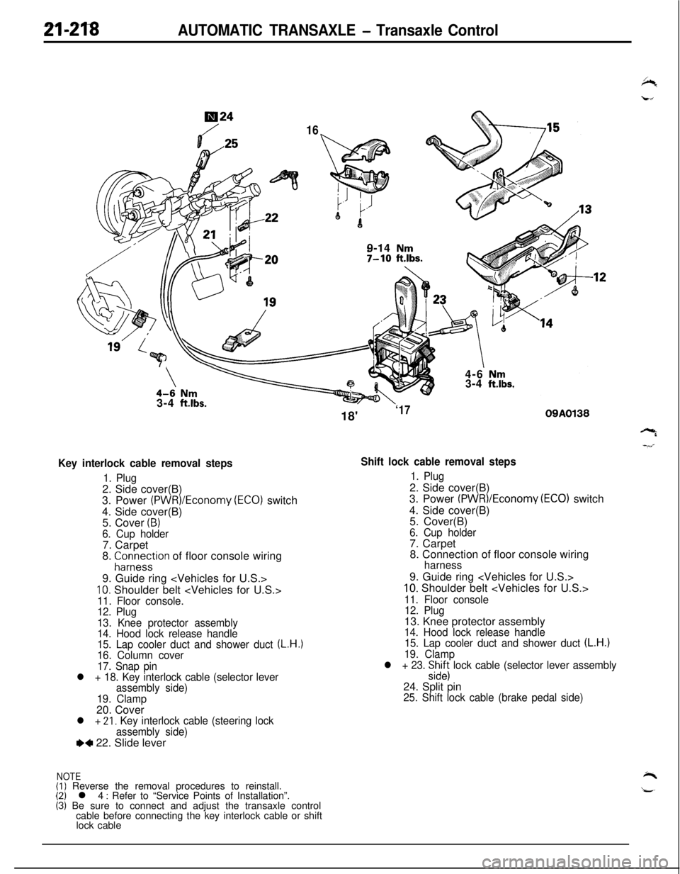
Key interlock cable removal steps
1. Plug2. Side cover(B)
3. Power
(PWR)/Economy (ECO) switch
4. Side cover(B)
5. Cover
(B)6. Cup holder7. Carpet
8.
;ir;eystion of floor console wiring
9. Guide ring
10. Shoulder belt 11. Floor console.
12. Plug
13. Knee protector assembly
14. Hood lock release handle
15. Lap cooler duct and shower duct
(L.H.)16. Column cover
17. Snap pin
l + 18. Key interlock cable (selector lever
assembly side)
19. Clamp20. Cover
l + 21, Key interlock cable (steering lock
assembly side)
e+ 22. Slide lever
NOTE(I) Reverse the removal procedures to reinstall.(2) l 4 : Refer to “Service Points of Installation”.(3) Be sure to connect and adjust the transaxle control
cable before connecting the key interlock cable or shift
lock cable18'
‘1709A0138
Shift lock cable removal steps
1. Plug2. Side cover(B)
3. Power
(PWR)/Economv (EC01 switch
4. Side cover(B)
’5. Cover(B)
6. Cup holder7. Carpet
8. Connection of floor console wiring
harness9. Guide ring
10. Shoulder belt
11. Floor console
12. Plug13. Knee protector assembly
14. Hood lock release handle
15. Lap cooler duct and shower duct (L.H.)19. Clamp
l + 23. :izs lock cable (selector lever assembly24. Split pin
25. Shift lock cable (brake pedal side)
Page 913 of 1216
AUTOMATIC TRANSAXLE - Transaxle Control
09AOll5
09AOO39
Neutral position
INSPECTIONN2ucAtll Check the control cable for function and for damage.8
Check the bushing for wear or damage.
POWER (PWR)/ECONOMY (ECO) SWITCH
Check for continuity between terminals when the switch is OFF
and when ON.
Terminal 1III
II ’
NOTEO-O indicates that there is continuity between the terminals.
OVERDRIVE CONTROL SWITCH
Check for continuity between terminals when the switch is OFF
and when ON.
ON (Overdrive activation)00
OFF (Overdrive non-activation)03
NOTE
0-O indicates that there is continuity between the terminals.
SERVICE POINTS OF INSTALLATIONN21lDAO30. INSTALLATION OF TRANSAXLE CONTROL CABLE
Move the selector lever and the inhibitor switch to the “N”
position, and install the transaxle control cable.
Page 915 of 1216
AUTOMATIC TRANSAXLE - Transaxle Control
DISASSEMBLY AND REASSEMBLY (SELECT LEVER ASSEMBLY)N210E--2.0 Nm or more
1.4
ft.lbs. or more
2.0 Nm or more
1.4
ft.lbs. or more
/1.0-2.0 Nm0.7-1.4 ft.lbs.14-20 Nm
lo-14 ft.lbs.
Disassembly steps
4+1. Overdrive control switch connector2.Cover3.Selector knob::4.Overdrive controlswitchbutton
5. Overdrive control switch
6.Pinl * 7. Pushbutton
ea8.Spring9.Indicator panel10.Slider11. indicator panel lower
12.Socket assembly
OSA0135
*413.Sleeve14.Lever assemblyI)+15.Bushing
16.Pipe17.Split pinl * 18. Lock cam19.Bracket assembly
NOTE(I) Reverse the disassembly procedures to reassemble.(2) ++ : Refer to “Service Points of Disassembly”.(3) l + : Refer to “Service Points of Reassembly”.
Sciewdriver
SERVICE POINTS OF DISASSEMBLYN21OFAC1. REMOVAL OF OVERDRIVE CONTROL SWITCH CON-
NECTORDisconnect the overdrive control switch connector and
then remove the terminal from the overdrive control
switch connector.
Page 916 of 1216

21-222AUTOMATIC TRANSAXLE - Transaxle Control
OSAOO88Lock
Farn
09A0136
09ROll6
LApply grease
here.
I
Sleeve
Lever/ assembly
09AOO43J
I
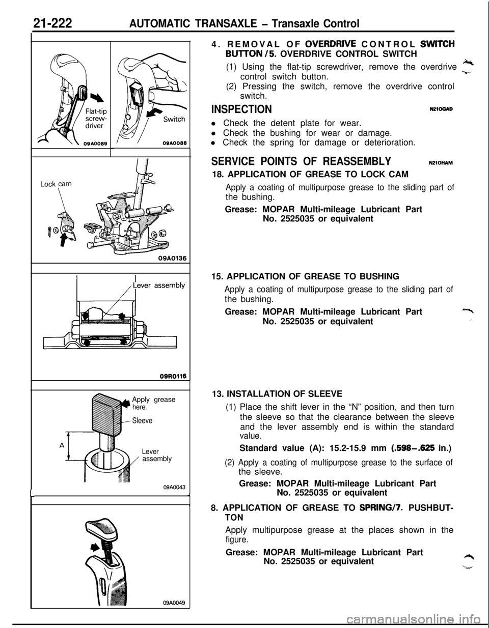
09AOO494. REMOVAL OF
OVERDRJVE CONTROL SWlTCH
BUlTON /5. OVERDRIVE CONTROL SWITCH
(1) Using the flat-tip screwdriver, remove the overdrive
J%control switch button.-r,(2) Pressing the switch, remove the overdrive control
switch.
INSPECTIONN21ocuDl Check the detent plate for wear.
l Check the bushing for wear or damage.
l Check the spring for damage or deterioration.
SERVICE POINTS OF REASSEMBLYNZlOHAM18. APPLICATION OF GREASE TO LOCK CAM
Apply a coating of multipurpose grease to the sliding part ofthe bushing.
Grease: MOPAR Multi-mileage Lubricant Part
No. 2525035 or equivalent
15. APPLICATION OF GREASE TO BUSHING
Apply a coating of multipurpose grease to the sliding part ofthe bushing.
Grease: MOPAR Multi-mileage Lubricant Part
No. 2525035 or equivalent
13. INSTALLATION OF SLEEVE
(1) Place the shift lever in the “N” position, and then turn
the sleeve so that the clearance between the sleeve
and the lever assembly end is within the standard
value.Standard value (A): 15.2-15.9 mm
(.598-.625 in.)
(2) Apply a coating of multipurpose grease to the surface ofthe sleeve.
Grease: MOPAR Multi-mileage Lubricant Part
No. 2525035 or equivalent
8. APPLICATION OF GREASE TO SPRINGI7. PUSHBUT-
TONApply multipurpose grease at the places shown in the
figure.Grease: MOPAR Multi-mileage Lubricant Part
No. 2525035 or equivalent
Y‘,#
Page 917 of 1216
AUTOMATIC TRANSAXLE - Transaxle Oil Cooler Hoses2 I*-223TRANSAXLE OIL COOLER HOSES
NZlSA-A
- REMOVAL AND INSTALLATION
3-5
Nm2-4 ftlbs.
4-6
Nm3-4 ftlbs.
09AOO41
Removal steps
1. Hose clamp
4*2. Oil cooler hose assembly
NOTE(1) Reverse the removal procedures to reinstall.(2) 4e : Refer to “Service Points of Removal”.
SERVICE POINTS OF REMOVALNZISSAD2. REMOVAL OF OIL COOLER HOSE ASSEMBLY
Caution
1. Take care not to spill the transaxle fluid when
removing components.
2. After removing the oil cooler hose assembly, plug
so that foreign materials cannot enter the transaxle.
INSPECTIONm1scAFl Check the hose for crack, damage and clog.
l Check for rusted or clogged radiator oil cooler.
Page 918 of 1216

21-224AUTOMATIC TRANSAXLE - Transaxle Oil Cooler
TRANSAXLE OIL COOLER
REMOVAL AND INSTALLATION
OQA01691
30-35 Nm
22-25 ft.lbs.
/I1’
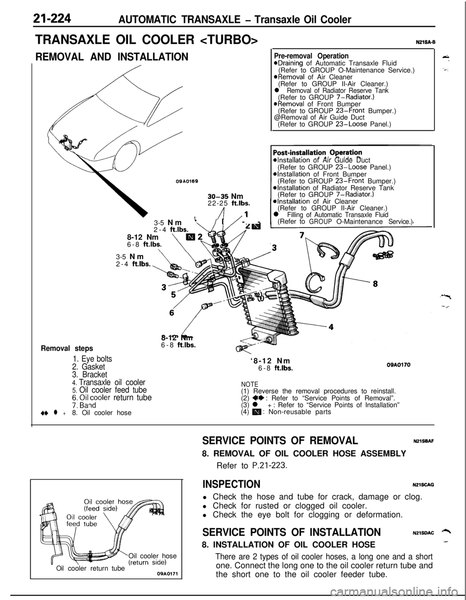
Removal steps
1. Eye bolts
2. Gasket3-5 Nm
‘\/I/ --
2-4
ftlbs.8-12 Nm
m26-8 ft.lbs.\\
N21SA-B
Pre-removal OperationeDraining of Automatic Transaxle Fluid
(Refer to GROUP O-Maintenance Service.)
@Removal of Air Cleaner
(Refer to GROUP II-Air Cleaner.)
l Removal of Radiator Reserve Tank(Refer to GROUP 7-Radiator.)
@Removal of Front Bumper
(Refer to GROUP 23-Front Bumper.)
@Removal of Air Guide Duct
(Refer to GROUP
23-Loose Panel.)
*Installation of Air Guide Duct
(Refer to GROUP 23-Loose Panel.)*Installation of Front Bumper
(Refer to GROUP 23-Front Bumper.)@Installation of Radiator Reserve Tank
(Refer to GROUP 7-Radiator.)
*Installation of Air Cleaner
(Refer to GROUP II-Air Cleaner.)
l Filling of Automatic Transaxle Fluid(Refer toGROUPO-MaintenanceService.)3-5 Nm
2-4
ftlbs.8-12 Nm
6-8
ft.lbs.‘8-12 Nm
6-8
ftlbs.OBAOl703. Bracket
4. Transaxle oil cooler5. Oil cooler feed tubeNOTE(1) Reverse the removal procedures to reinstall.
7: ~i&~oler return tube(2) ++ : Refer to “Service Points of Removal”.
(3) l + : Refer to “Service Points of Installation”
+e l +8. Oil cooler hose(4) m : Non-reusable parts
Oil cooler hose
Oilcoolerreturn tube09A0171
&.
-=-.
SERVICE POINTS OF REMOVALNZlSBAF8. REMOVAL OF OIL COOLER HOSE ASSEMBLY
Refer to
P.21-223.
INSPECTIONN2lSCAGl Check the hose and tube for crack, damage or clog.
l Check for rusted or clogged oil cooler.
l Check the eye bolt for clogging or deformation.
SERVICE POINTS OF INSTALLATIONN2lSDAC ‘-+8. INSTALLATION OF OIL COOLER HOSE_
There are 2 types of oil cooler hoses, a long one and a shortone. Connect the long one to the oil cooler return tube and
the short one to the oil cooler feeder tube.