Page 1182 of 1216
24-38HEATERS AND AIR CONDITIONING - Compressor
2OAOO87
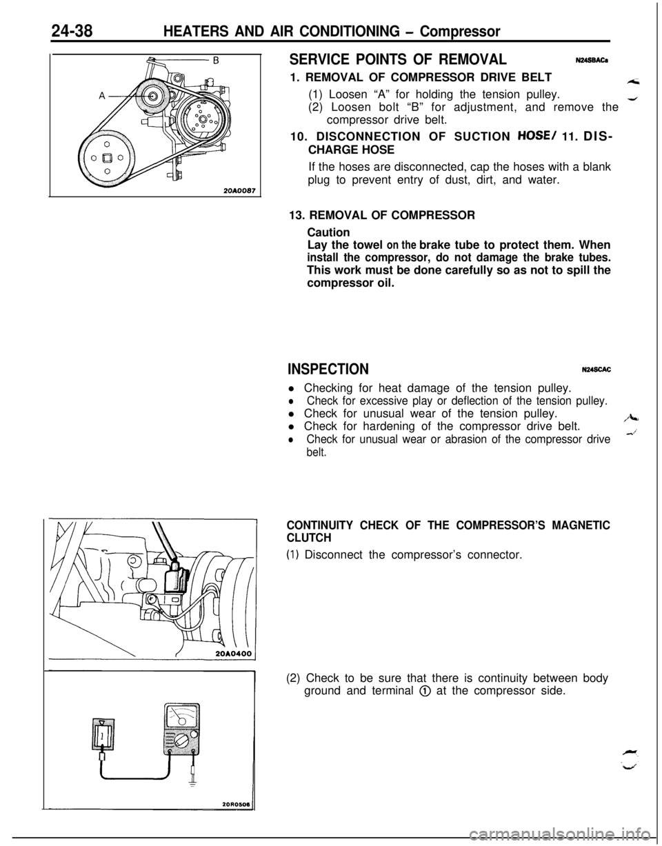
SERVICE POINTS OF REMOVALN248BACa1. REMOVAL OF COMPRESSOR DRIVE BELT
A;i(1) Loosen “A” for holding the tension pulley.
(2) Loosen bolt “B” for adjustment, and remove the
4compressor drive belt.
10. DISCONNECTION OF SUCTION
HOSE/ 11. DIS-
CHARGE HOSE
If the hoses are disconnected, cap the hoses with a blank
plug to prevent entry of dust, dirt, and water.
13. REMOVAL OF COMPRESSOR
Caution
Lay the towel on the brake tube to protect them. When
install the compressor, do not damage the brake tubes.This work must be done carefully so as not to spill the
compressor oil.
INSPECTIONN248CACl Checking for heat damage of the tension pulley.
lCheck for excessive play or deflection of the tension pulley.l Check for unusual wear of the tension pulley.
l Check for hardening of the compressor drive belt.
/J+-
lCheck for unusual wear or abrasion of the compressor drive&’
belt.
CONTINUITY CHECK OF THE COMPRESSOR’S MAGNETIC
CLUTCH
(1) Disconnect the compressor’s connector.
(2) Check to be sure that there is continuity between body
ground and terminal
@ at the compressor side.
Page 1183 of 1216
HEATERS AND AIR CONDITIONING - Compressor24-39
\/20A0400
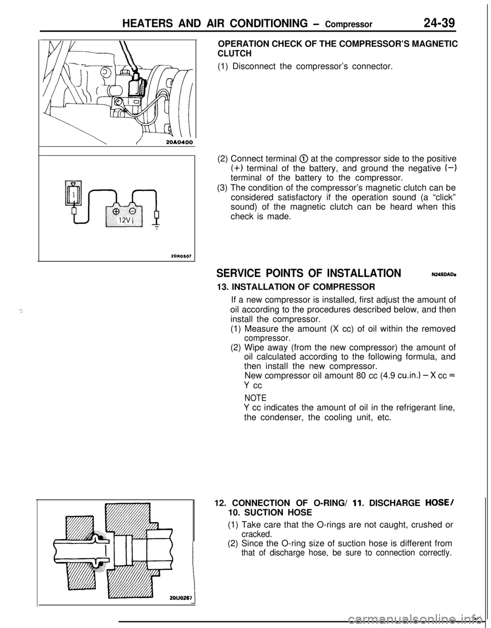
20R0507OPERATION CHECK OF THE COMPRESSOR’S MAGNETIC
CLUTCH(1) Disconnect the compressor’s connector.
(2) Connect terminal
@ at the compressor side to the positive(+) terminal of the battery, and ground the negative
(-)terminal of the battery to the compressor.
(3) The condition of the compressor’s magnetic clutch can be
considered satisfactory if the operation sound (a “click”
sound) of the magnetic clutch can be heard when this
check is made.
SERVICE POINTS OF INSTALLATIONN248DADa13. INSTALLATION OF COMPRESSOR
If a new compressor is installed, first adjust the amount of
oil according to the procedures described below, and then
install the compressor.
(1) Measure the amount (X cc) of oil within the removed
compressor.(2) Wipe away (from the new compressor) the amount of
oil calculated according to the following formula, and
then install the new compressor.
New compressor oil amount 80 cc (4.9
cu.in.) - X cc =
Y cc
NOTE
Y cc indicates the amount of oil in the refrigerant line,
the condenser, the cooling unit, etc.
12. CONNECTION OF O-RING/
11. DISCHARGE HOSE/
10. SUCTION HOSE
(1) Take care that the O-rings are not caught, crushed or
cracked.(2) Since the O-ring size of suction hose is different from
that of discharge hose, be sure to connection correctly.
1t
/
Page 1184 of 1216
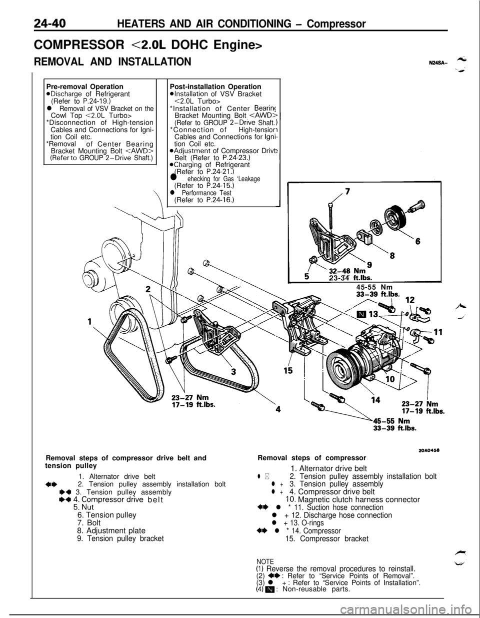
24-40HEATERS AND AIR CONDITIONING - CompressorCOMPRESSOR
<2.0L DOHC Engine>
REMOVAL AND INSTALLATIONPre-removal OperationaDischarge of Refrigerant
(Refer to
P.24-19.)l Removal of VSV Bracket on theCowl Top <2.0L Turbo>
*Disconnection of High-tension
Cables and Connections for Igni-
tion Coil etc.
*Removal
of Center Bearing
Bracket Mounting Bolt
(Referto GROUP 2-Drive Shaft.)Post-installation Operation
*Installation of VSV Bracket<2.0L Turbo>
*Installation of Center
Bearin!Bracket Mounting Bolt
*Adjustment of Compressor Drivt
Belt (Refer to P.24-23.)Kharging of Refrigerant
(Refer to P.24-21.)l ehecking for Gas ‘Leakage(Refer to P.24-15.)l Performance Test(Refer to P.24-16.)
N24SA.-tension pulley
1. Alternator drive belt
4*2. Tension pulley assembly installation boltI)+ 3. Tension pulley assembly~~ 2: Grpressor dnve belt
6. Tension pulley
7. Bolt
8. Adjustment plate
9. Tension pulley bracket23-34
ft.lbs.45-55 Nm
33-39 ft.lbs.
2OAO4.58Removal steps of compressor drive belt andRemoval steps of compressor
1. Alternator drive belt
l *2. Tension pulley assembly installation boltl +3. Tension pulley assemblyl +4. Compressor drive belt10. Magnetic clutch harness connector+* l * 11. Suction hose connectionl + 12. Discharge hose connectionl + 13. O-rings
** l * 14. Compressor15. Compressor bracket
NOTE(I) Reverse the removal procedures to reinstall.(2) +e : Refer to “Service Points of Removal”.
(3) l + : Refer to “Service Points of Installation”.(4) m : Non-reusable parts.
Page 1186 of 1216
COMPRESSOR
DISASSEMBLY AND REASSEMBLY24-28 Nm
18-21
ft.lbs.Magnetic clutch disassembly steps
4eW ;. tIu;h hub
3:Snap ring4*4.Rotor
5. Snap ring
l 46.Clutch coilShaft seal disassembly steps
4*
l + ;. F;;t housing
9:Felt holder
10.Snap ring
4e l + 11. Shaft seal
12.O-ring
NOTE(1) Reverse the disassembly procedures to reassemble.(2) ~~ : Refer to “Service Points of Disassembly”.
(3) W : Refer to “Service Points of Reassembly”.(4) m : Non-reusable parts.
ISERVICE POINTS OF DISASSEMBLYN24SFAC\
2OW857
\1. REMOVAL OF CLUTCH HUB
(1) Fix the compressor with a vise. At this time, the rear
housing of the compressor must be in contact with the
vise.(2) If the clutch hub cannot be pulled off by hand, screw in
an 8 mm
(.315 in.) completely threaded bolt so as to
raise the clutch hub so it can be removed.
4. REMOVAL OF ROTOR
Using a plastic hammer, lightly tap the rotor off the shaft.
Page 1187 of 1216

HEATERS AND AIR CONDITIONING - Compiessor24-43
2OW660
2OW8628. REMOVAL OF FELT
Using a flat-tip
0 screwdriver, remove the felt from the
front housing.
11. REMOVAL OF SHAFT SEAL
Using a flat-tip
0 screwdriver, remove the shaft seal from
the front housing.
INSPECTIONN24TGAH
lCheck the surface of the clutch hub for scoring or bluing.
l Check the surface of the rotor for scoring or bluing.
l Check the sealing surfaces for cracks, scratches and
deformation.
lCheck the front housing for cracks or scoring on the sealing
surfaces.l Check the compressor shaft for scoring.
SERVICE POINTS OF REASSEMBLYN24StiAC11. INSTALLATION OF SHAFT SEAL
(1) Lubricate the shaft seal with specified compressor oil.
Specified compressor oil:
DENS0 OIL 6 or SUNISO 5GS(2) Set the shaft seal to the front housing so that the
projection side of the center ring is at the shaft seal
side.(3) Using a 21 mm
(.83 in,) socket, install the shaft seal.
7. INSTALLATION OF FRONT HOUSING
(1) Apply the specified compressor oil on the shaft.
Specified compressor oil:
DENS0 OIL 6 or SUNISO 5GS(2) Taking care to prevent injuring the lip area of the shaft
tool, mount the front housing.
(3) Mount the bolt on the shaft, and then measure the
shaft starting torque.
Standard value: 5.0 Nm (43
in.lbs.) or less
(4) Remove the bolt from the shaft.
Page 1188 of 1216
24-44HEATERS AND AIR CONDITIONING - Coinpressiir
l-l12”
2OW8636. INSTALLATION OF CLUTCH CO&
The clutch coil must be aligned with the pin in, the
compression housing.
1. INSTALLATION OF CLUTCH HUB
(1) Connect the magnetic clutch to the battery.
(2) The clutch hub will be attracted to and fit closely to the
rotor.(3) Use
‘a shim(s) to adjust so that the -amountof
movement of the clutch hub is as described below.
Standard value:
0.35-0.65 mm (.014-.026 in.)
NOTERemove clearance adjusting shims to decrease clutch
clearance. Add shims selected from the following table
to increase clutch celarance.
Clearance Adjustment Shims
Part No.Thickness
I949013-74801 0.1 mm (.004 in.)1
I949013-76801 0.2 mm LOO8 in.)1949013-75100.5 mm
LO20 in.)I
3 , z,0’i,,,
Page 1195 of 1216
HEATERS AND AIR CONDITIONING- Engine Coolant Temperature Switch24-51
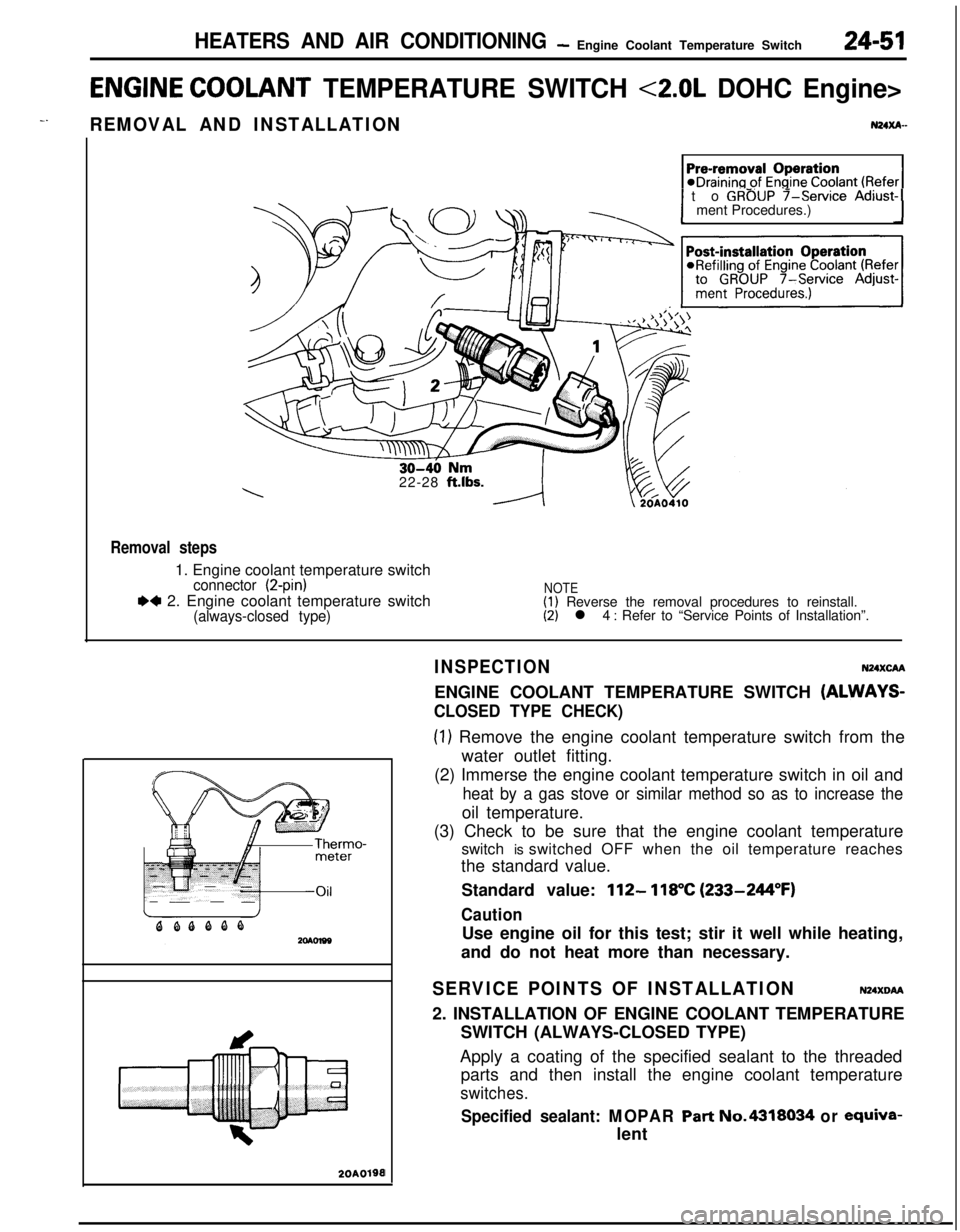
ENGINE COOLANT TEMPERATURE SWITCH <2.0L DOHC Engine>
-.REMOVAL AND INSTALLATIONN24xA-
1 to GROUP f-service Adjust-1ment Procedures.)
22-28
ft.lbs.
Removal steps1. Engine coolant temperature switch
connector (2-pin)
.4 2. Engine coolant temperature switch(always-closed type)
NOTE(1) Reverse the removal procedures to reinstall.(2) l 4 : Refer to “Service Points of Installation”.
20A0190I
INSPECTIONN24XcAAENGINE COOLANT TEMPERATURE SWITCH
(ALWAYS-
CLOSED TYPE CHECK)
(1) Remove the engine coolant temperature switch from the
water outlet fitting.
(2) Immerse the engine coolant temperature switch in oil and
heat by a gas stove or similar method so as to increase theoil temperature.
(3) Check to be sure that the engine coolant temperature
switch is switched OFF when the oil temperature reaches
the standard value.
Standard value:
112- 118°C (233-244°F)
CautionUse engine oil for this test; stir it well while heating,
and do not heat more than necessary.
SERVICE POINTS OF INSTALLATIONN24XDM2. INSTALLATION OF ENGINE COOLANT TEMPERATURE
SWITCH (ALWAYS-CLOSED TYPE)
Apply a coating of the specified sealant to the threaded
parts and then install the engine coolant temperature
switches.
Specified sealant: MOPAR Part No.4318034 or ewiva-lent
Page 1198 of 1216
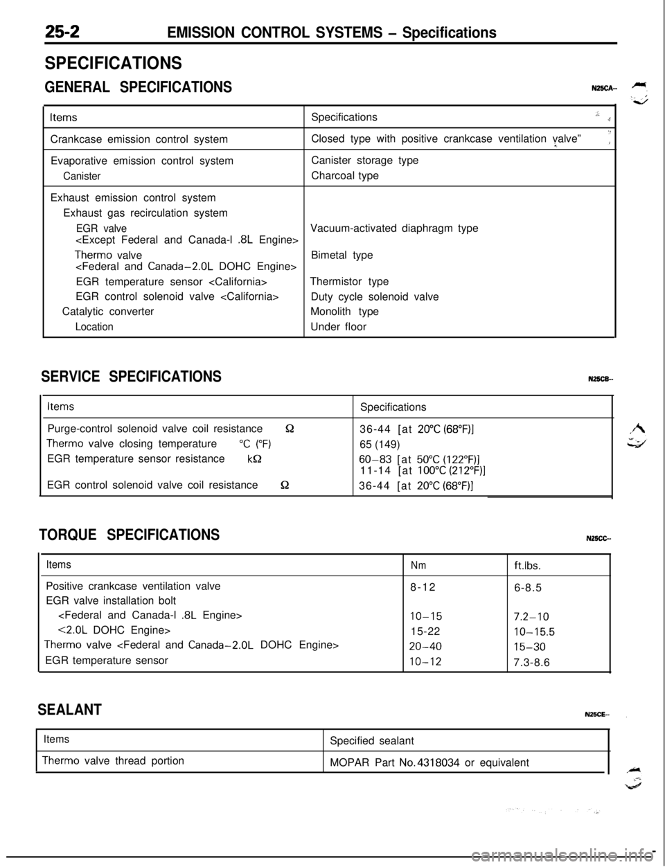
EMISSION CONTROL SYSTEMS - Specifications
SPECIFICATIONS
GENERAL SPECIFICATIONSN25CA-ItemsSpecifications
.,:..rCrankcase emission control systemClosed type with positive crankcase ventilation valve”I
‘:Evaporative emission control systemCanister storage type
CanisterCharcoal type
Exhaust emission control system
Exhaust gas recirculation system
EGR valveVacuum-activated diaphragm type
.8L Engine>
Therm0 valveBimetal type
EGR temperature sensor Thermistor type
EGR control solenoid valve
Duty cycle solenoid valve
Catalytic converterMonolith type
LocationUnder floor
SERVICE SPECIFICATIONSN25CB-
ItemsSpecifications
Purge-control solenoid valve coil resistance
&236-44 [at 20°C (68”F)I
Therm0 valve closing temperature“C (“F)65 (149)
EGR temperature sensor resistance
kQ60-83 [at 50°C (122”F)]11-14 [at
100°C (212”F)]EGR control solenoid valve coil resistance
S236-44 [at 20°C (68”F)]
TORQUE SPECIFICATIONSN25CC-
ItemsPositive crankcase ventilation valve
EGR valve installation bolt
.8L Engine>
<2.0L DOHC Engine>
Therm0 valve
EGR temperature sensor
Nmftlbs.8-12
6-8.5
IO-157.2-1015-22
10-15.5
20-4015-30
10-127.3-8.6
SEALANT
Items
Therm0 valve thread portionSpecified sealant
MOPAR Part No.4318034 or equivalent