1991 MITSUBISHI ECLIPSE low oil pressure
[x] Cancel search: low oil pressurePage 860 of 1216

21-166AUTOMATIC TRANSAXLE - SDecifications
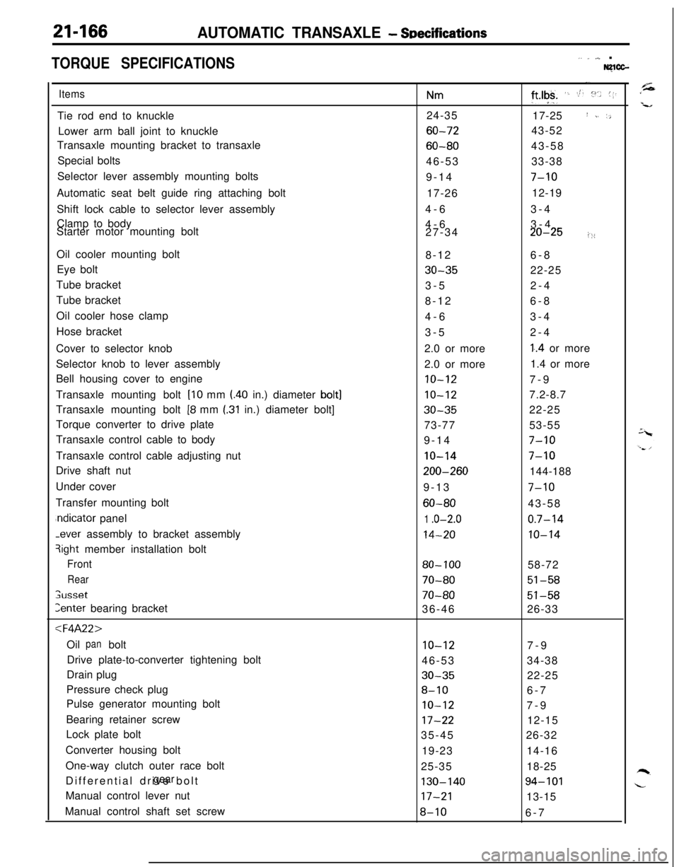
TORQUE SPECIFICATIONS,. _ ,,,_ .Nglcc-
ItemsTie rod end to knuckle
Lower arm ball joint to knuckle
Transaxle mounting bracket to transaxle
Special bolts
Selector lever assembly mounting bolts
Automatic seat belt guide ring attaching bolt
Shift lock cable to selector lever assembly
Clamp to body
Starter motor mounting bolt
Oil cooler mounting bolt
Eye bolt
Tube bracket
Tube bracket
Oil cooler hose clamp
Hose bracket
Cover to selector knob
Selector knob to lever assembly
Bell housing cover to engine
Transaxle mounting bolt
[lo mm l.40 in.) diameter bolt]Transaxle mounting bolt
[8 mm I.31 in.) diameter bolt]
Torque converter to drive plate
Transaxle control cable to body
Transaxle control cable adjusting nut
Drive shaft nut
Under cover
Transfer mounting boltndicator panel-ever assembly to bracket assembly
3ight member installation bolt
Front
Rear
;usset
Zenter bearing bracket
:l=4A22>Oil bolt
panDrive plate-to-converter tightening bolt
Drain plug
Pressure check plug
Pulse generator mounting bolt
Bearing retainer screw
Lock plate bolt
Converter housing bolt
One-way clutch outer race bolt
Differential drive bolt
gearManual control lever nut
Manual control shaft set screw
Nm24-35
60-72
60-8046-53
9-14
17-26
4-6
4-6
27-34
8-12
30-353-5
8-12
4-6
3-5
2.0 or more
2.0 or more
10-12
10-12
30-3573-77
9-14
IO-14
200-2609-13
60-80
1 .o-2.0
14-20
80- 100
70-80
70-8036-46
10-1246-53
30-35
8-10
IO-12
17-2235-45
19-23
25-35
130-14017-21
8-10
-.
ft*lgk+ ‘. St. :“.. (1.17-25
I ~. ‘,43-52
43-58
33-38
7-1012-19
3-4
3-4
20-25i::6-8
22-25
2-4
6-8
3-4
2-4
1..4 or more
1.4 or more
7-9
7.2-8.7
22-25
53-55
7-10
7-10144-188
7-1043-58
0.7-14
10-1458-72
51-58
51-5826-33
7-9
34-38
22-25
6-7
7-9
12-15
26-32
14-16
18-25
94-10113-15
6-7
Page 869 of 1216

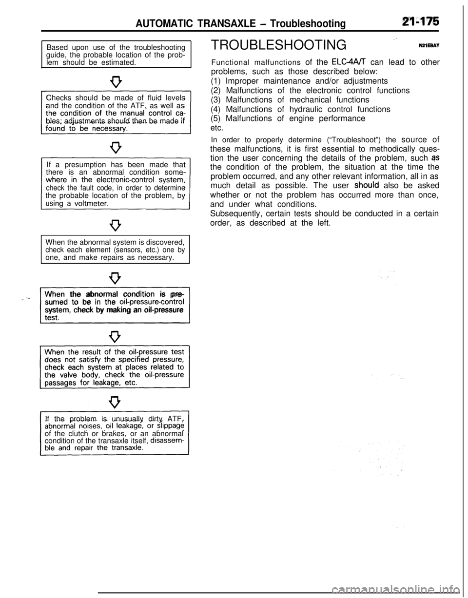
AUTOMATIC TRANSAXLE - TroubleshootingBased upon use of the troubleshooting
guide, the probable location of the prob-
lem should be estimated.
Checks should be made of fluid levels
and the condition of the ATF, as well as
bles; adjustments should then be made if
If a presumption has been made that
there is an abnormal condition some-
check the fault code, in order to determinethe probable location of the problem, by
When the abnormal system is discovered,
check each element (sensors, etc.) one byone, and make repairs as necessary.
“~^II_When the abnormal condition is pre-
sumed to be in the
orI-pressure-controlsystem, check by making an oil-pressure
If the problem is unusually dirty ATF,
of the clutch or brakes, or an abnormal
condition of the transaxle itself,
disassem-TROUBLESHOOTING
”N21EeAYFunctional malfunctions of the ELC4A/T can lead to other
problems, such as those described below:
(1) Improper maintenance and/or adjustments
(2) Malfunctions of the electronic control functions
(3) Malfunctions of mechanical functions
(4) Malfunctions of hydraulic control functions
(5) Malfunctions of engine performance
etc.In order to properly determine (“Troubleshoot”) the source of
these malfunctions, it is first essential to methodically ques-
tion the user concerning the details of the problem, such qs
the condition of the problem, the situation at the time the
problem occurred, and any other relevant information, all in as
much detail as possible. The user
shoutd also be asked
whether or not the problem has occurred more than once,
and under what conditions.
Subsequently, certain tests should be conducted in a certain
order, as described at the left.
Page 877 of 1216

AUTOMATIC TRANSAXLE - Troubleshooting214%3
TRANSAXLE CONTROL UNIT
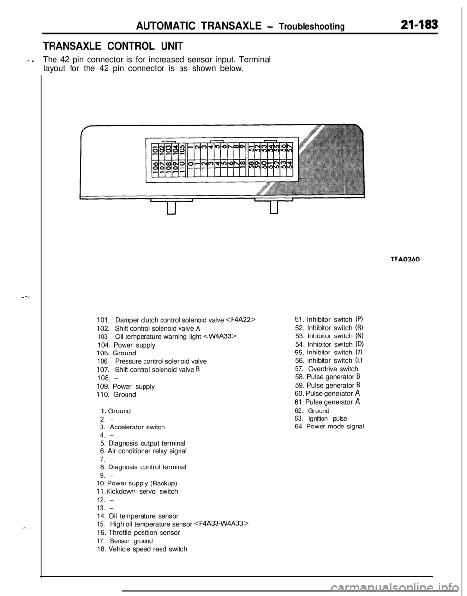
-‘” .The 42 pin connector is for increased sensor input. Terminal
layout for the 42 pin connector is as shown below.TFA0360
101.Damper clutch control solenoid valve
102.Shift control solenoid valve A
103.Oil temperature warning light
105. Ground
106.Pressure control solenoid valve
107.Shift control solenoid valve B108.
-
109. Power supply
110. Ground
1. GroundL.
-
3.Accelerator switch
4.-5. Diagnosis output terminal
6. Air conditioner relay signal
7.-8. Diagnosis control terminal
9.-
IO. Power supply (Backup)
11. Kickdown servo switch
12.-
13.-14. Oil temperature sensor
15.High oil temperature sensor
16. Throttle position sensor
17.Sensor ground18. Vehicle speed reed switch
51. Inhibitor switch (PI52. Inhibitor switch
(8)53. Inhibitor switch
(N)54. Inhibitor switch
(D)
55. Inhibitor switch (2)56. inhibitor switch
(L)
57.Overdrive switch
58. Pulse generator
B59. Pulse generator
B60. Pulse generator A
61. Pulse generator A
62.Ground63.Ignition pulse64. Power mode signal
Page 889 of 1216

AUTOMATIC TRANSAXLE - Troubleshooting21'495
OIL PRESSURE TESTS
1.
2.
3.
4.
5.Completely warm up the transaxle.
.”Raise the vehicle by using a jack so that the drive wheels
can be rotated.
Connect an engine tachometer and place it in a position
where it’s easy to see.
Attach the special oil-pressure gauge
(C-3292 or C-3293)and the adaptor
(MD998332) to each oil-pressure outlet
port.When the reverse pressure is to be tested, the 3,000
kPa(400 psi) type of gauge should be used.
Measure the oil pressure under various conditions , and
check to be sure that the measured results are within the
standard value range shown in the “Standard oil pressure
table” below.
If the oil pressure is not within the specified range, check
and repair as described in the section “Remedial steps if oilpressure is not normal” on the next page.
m // @ Kickdown brake
Page 890 of 1216

21-196AUTOMATIC TRANSAXLE - TroubleshootingStandard Oil Pressure Table
F4A22
Standard oil pressure kPa (psi)Conditions
1NIdlingNeutral360-490(51-70)
2DIdling2nd gear360-490(51-70)
3&ON,Approx.360-4902,5004th gear(51-70)830-900830-900(118-128) -(118-128) -
830-900830-900830-900350-450(118-128)(118-128)(118-128) -(50-6434(SWF)oFF, ,A2pp5boox.3rd gear360-490(51-70)
52Approx.2nd gear360-4902,500(51-70)830-900(118-128)-
6LAp”60”.1st gear360-490(51-70)-I-
1,640-2.240(233-319)-
l-41,500 (213)or more1 or more I
TStandard oil pressure kPa (psi)
0Kickdown
brakepressure
(Release)
@IFrontclutchpressure
0Rearclutchpressure
c3Endclutchpressure
0Low-reverse
brakepressure
00ShiftpositionReducing KickM;vnpressurepressure
-l---l
(APPM
Neutral !r$I$$ -
c3Torque-converter
pressure
h
No.SelectleverpositionEnginespeed
m
Idling
IdlingApprox.2,500Approx.
1,000Approx.2,500
N-
-
LI
*D730-830(104-118)2nd gear (51-68)I I360-480 100-210(14-30)-
830-900(118-128)(SWFON,-
830-900(118-128)830-900(118-128)4SW%FF:830-900(118-128)830-900(118-128)
2450-650(64-92)
*
450-650(64-92)
830-900(118-128)
830-900(118-128)
-
-6,640-2.24C
(233-319),640-2.24C(233-319)I ,640-2.24C(233-319)III
17-
1.500 (213)or more1,500 (213)or more1,500 (213)or more
NOTEmust be 10 kPa (1.4 psi) or less.SW-ON: Switch ON the overdrive control switchSW-OFF: Switch OFF the overdrive control switchI+: Hydraulic pressure is generated, but not the standard value.
Page 891 of 1216

AUTOMATIC TRANSAXLE - TroubleshootingRemedial Steps If Oil Pressure Is Not Normal
F4A22.,,‘
frouble symptomProbable causeRemedy1;
I. *Line pressures
a.Clogging of oil filtera.Visually inspect the oil filter; replace the oil filte
are all low (or high).
if it is clogged.
NOTEb.Improper adjustment of oil press-b.Measure line pressure @ (kickdown brake*“Line pressures”ure (line pressure) of regulator
pressure); if the pressure is not the standard
refers to oil
ress-ures@,@, 4 and
8
valvevalue, readjust the line pressure, or, if neces-sary, replace the valve body assembly.
@in the “Standardc.Sticking of regulator valvec.Check the operation of the regulator valve;oil pressure table”repair if necessary, or replace the valve body
on the previousassembly.
page.d.Looseness of valve body tighten-d.Tighten the valve body tightening bolt and
ing partinstallation bolt.‘- ,
e.Improper oil pump dischangee.Check the side clearance of the oil pump gehr;
pressurereplace the oil pump assembly if necessary.
I. Improper reducinga.Improper line pressurea.Check the @ kickdown brake pressure (line
pressurepressure); if the line pressure is not the
standard value, check as described in item 1
above.
b.Clogging of the filter (L-shapedb.Disassemble the valve body assembly and
type) of the reducing-pressure cir-check the filter; replace the filter if it is clogged.cuit
c.Improper adjustment of the re-c.Measure the @I reducing pressure; if it is not
ducing pressurethe standard value, readjust, or replace the
valve body assembly.
d.Sticking of the reducing valved.Check the operation of the reducing valve; if
necessary, repair it, or replace the valve body
assembly.
e.Looseness of valve body tighten-e.Tighten the valve body tightening bolt and
ing partinstallation bolt.
#. Improper kick-a.Malfunction of the D-ring or seala. Disassemble the kickdown servo and check
down brake press-ring of the sleeve or kickdownwhether the seal ring or D-ring is damaged.
ureservo piston.If it is cut or has scratches, replace the seal ring
or D-ring.
b.Looseness of valve body tighten-b.Tighten the valve body tightening bolt and
ing partinstallation bolt.
c.Functional malfunction of thec.Replace the valve body assembly.
valve body assembly
. Improper front
clutch pressure
a.Malfunction of the D-ring or seala. Disassemble the kickdown servo and check
ring of the sleeve or kickdownwhether the seal ring or-D-ring is damaged.servo piston.
If it is cut or has scratches, replace the seal ring
or D-ring.
b.Looseness of valve body tighten-b.Tighten the valve body tightening bolt and
ing partinstallation bolt.c.Functional malfunction of thec.Replace the valve body assembly.
valve body assembly
d.Wear of the front clutch piston ord.Disassemble the transaxle itself and check
retainer, or malfunction of the
@whether or not there is wear of the front clutch
D-ring, @ seal, ring.piston and retainer inner circumference, or
ra;;; to the figure on the nextdamage of the D-ring. If there is any wear or
damage, replace the piston, retainer, D-ring
and/or seal ring.
1. Improper endclutch pressure
a.Malfunction of a D-ring @or seala.Disassemble the end clutch and check the sealring 0, @of the end clutch or
O-ring @I of the pipe (Refer to thering, D-ring of the piston, seal ring of thefollowing figure.)retainer, etc.; replace if there are cuts, scars,
scratches or damage.
b.Looseness of valve body tighten-b.Tighten the valve body tightening bolt and
ing partinstallation bolt.c.Functional malfunction of thec.Replace the valve body assembly.
valve body assembly
Page 892 of 1216

21-198AUTOMATIC TRANSAXLE - Troubleshooting
Trouble symptom6. improper
low-
reverse brake
pressure
7. Improper torque
converter pressureProbable causea.O-ring between valve body and
transaxle damaged or missing
b.Looseness of valve body tighten-
ing part
c.Functional malfunction of the
valve body assembly
d.Malfunction of the O-ring 0 of thelow-reverse brake piston or the
O-ring
0 of the retainer (Refer tothe figure below.)
a.Sticking of the damper clutch
control solenoid valve (DCCSV) or
the damper clutch control valve.
b.Clogging or leaking of the oil
cooler and/or piping
2.Damaged seal ring @of the input
shaft (Refer to the figure below.)
3.Malfunction of the torque conver-
ter
Remedy
a.Remove the valve body assembly and check to
be sure that the O-ring at the upper surface of
the upper valve body is not
missinor dam-
aged; install or replace the O-ring i7necessary.
b.Tighten the valve body tightening bolt andinstallation bolt.
c.Replace the valve body assembly.
d.Disassemble the transaxle itself and check the
O-ring for damage; replace if there are cuts,
scars, scratches or damage.
a.Check the operation of the damper clutch
system and the DCCSV.
b.Repair or replace, as necessary, the cooler
and/or piping.
c.Disassemble the transaxle itself and check for
damage of the seal ring; replace the seal ring if
there is damage.
d.Replace the torque converter.
@D-ring@Seal ring
-OD-ring@Seal ring
(@Seal ring
@O-ring
1750437
Page 893 of 1216

AUTOMATIC TRANSAXLE - Troubleshooting
F4A33-W4A33Trouble symptom
1. Line pressures areall low (or high).
NOTE* “Line pressures”
refers to oil
pressure @,@I, 0,0, @I and 0, inthe “Standard oil
pressure table” on
the previous page.
2. Improper reducing
pressure3. Improper
kickdown brake
pressure (Apply)
4. Improper
kickdown brake
pressure (Release)
5. Improper front
clutch pressureProbable cause
a.Clogging of oil filter
b.Improper adjustment of oil
pressure (line pressure of
regulator valve
c.Functional malfunction of valve
body assembly
d.Looseness of valve bodytightening part
e.Improper oil pump dischange
pressure
a.Clogging of the filter (L-shaped
type) of the reducing-pressurecircuit
b.Improper adjustment of oil
pressure
c.Functional malfunction of thevalve body assembly
a.Malfunction of the seal ring @,
D-ring @I or seal ring 0 of thesleeve of the kickdown servo
piston.
b.Functional malfunction of the
valve body assembly
a.Malfunction of the seal ring @,
D-ring @ or seal ring a> of thesleeve of the kickdown servo
piston.
b.Functional malfunctio? of the
valve body assembly
a.Malfunction of the seal ring @,
D-ring @or seal ring Q3 of thesleeve of the kickdown servo
piston.
b.Functional malfunction of the
valve body assembly
c.Wear of the front clutch piston or
retainer, or malfunction of theD-ring 0 or seal ring @.
Remedy
a.Visually inspect the oil filter; replace the oil filter
if it is clogged.
b.Measure line pressure @ (kickdown brake
pressure); if the pressure is not the standard
value, readjust the line pressure, or, if
necessary, replace the valve body assembly.
c.Replace the valve body assembly.
d.Tighten the valve body tightening bolt and
installation bolt.
e.Check the side clearance of the oil pump gear;
replace the oil pump assembly if necessary.
a.Disassemble the valve body assembly and
check the filter; replace the filter if it is clogged.
b.Measure the @ reducing pressure; if it is notthe standard value, readjust, or replace the
valve body assembly.
2.Replace the valve body assembly.
a.Disassemble the kickdown servo and check
whether the seal ring or D-ring is damaged.
If it is cut or has scratches, replace the seal ring
or D-ring.
3.Replace the valve body assembly.
3.Disassemble the kickdown servo and check
whether the seal ring or D-ring is damaged.
If it is cut or has scratches, replace the seal ring
or D-ring.
3.Replace the valve body assembly.
3.Disassemble the kickdown servo and checkwhether the seal ring or D-ring is damaged.
If it is cut or has scratches, replace the seal ring
or D-ring.
I.
Replace the valve body assembly.
:.Disassemble the transaxle itself and checkwhether or not there is wear of the front clutch
piston and retainer inner circumference, or
damage of the D-ring and/or seal ring. If there is
any wear or damage, replace the piston,
retainer, D-ring and/or seal ring.