1991 MITSUBISHI ECLIPSE low oil pressure
[x] Cancel search: low oil pressurePage 1146 of 1216
24-2HEATERS AND AIR CONDITIONING - Specifications
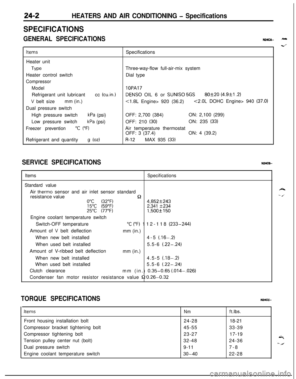
SPECIFICATIONS
GENERAL SPECIFICATIONSN24cA- -
ItemsSpecifications
Heater unit
TypeThree-way-flow full-air-mix system
Heater control switchDial type
Compressor
Model
lOPARefrigerant unit lubricantcc
(cu.in.1DENS0 OIL 6 or SUNISO 5GS80f20 (4.9&l .2)
V belt sizemm (in.)<1.8L Engine> 920 (36.2)<2.0L DOHC Engine> 940 (37.0)Dual pressure switch
High pressure switch
kPa (psi)OFF: 2,700 (384)ON: 2,100 (299)
Low pressure switch
kPa (psi)OFF: 210 (30)ON: 235 (33)
Freezer prevention“C (“F)Air temperature thermostat
OFF: 3 (37.4)ON: 4 (39.2)
Refrigerant and quantity
g bdR-12MAX 935 (33)
SERVICE SPECIFICATIONSN24CB.-
ItemsSpecifications
Standard valueAir
therm0 sensor and air inlet sensor standard
resistance value
n0°C (32°F)4,852f24315°C (59°F)2,341 f23425°C 177°F)1,500f 150Engine coolant temperature switch
Switch-OFF temperature
“C (“F) 112-118 (233-244)
Amount of
V belt deflection
mm (in.)
When new belt installed4-5
(.16-.2)When used belt installed5.5-6
(.22-.24)Amount of V-ribbed belt deflection
mm (in.)
When new belt installed4.5-5
(.18-.2)When used belt installed5.5-6
(.22-.24)
Clutch clearancemm (in.) 0.35-0.65 (.014-,026)
Condenser fan motor resistor resistance value
52 0.26-0.32
TORQUE SPECIFICATIONSN24CC-
ItemsNmft.lbs.Front housing installation bolt
24-2818-21
Compressor bracket tightening bolt
45-5533-39
Compressor tightening bolt
23-2717-19
Tension pulley center nut (bolt)
32-4824-36
Dual pressure switch
9-117-8
Engine coolant temperature switch
30-4022-28
k
- /.
Page 1154 of 1216
24-10HEATERS AND AIR CONDITIONING - Safety Precautions
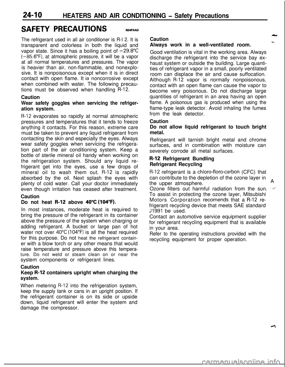
SAFETY PRECAUTIONSN24PAAD
The refrigerant used in all air conditioner is R-l 2. It istransparent and colorless in both the liquid and
vapor state. Since it has a boiling point of
-29.8”C(-85.6”F).
at atmospheric pressure, it will be a vapor
at all normal temperatures and pressures. The vaporis heavier than air, non-flammable, and nonexplo-
sive. It is nonpoisonous except when it is in direct
contact with open flame. It
ia noncorrosive except
when combined with water. The following precau-
tions must be observed when handling
R-12.Caution
Wear safety goggles when servicing the refriger-ation system.
R-12 evaporates so rapidly at normal atmospheric
pressures and temperatures that it tends to freeze
anything it contacts. For this reason, extreme care
must be taken to prevent any liquid refrigerant from
contacting the skin and especially the eyes. Always
wear safety goggles when servicing the refrigera-
tion part of the air conditioning system. Keep a
bottle of sterile mineral oil handy when working on
the refrigeration system. Should any liquid re-
frigerant get into the eyes, use a few drops of
mineral oil to wash them out.
R-12 is rapidly
absorbed by the oil. Next splash the eyes with
plenty of cold water. Call your doctor immediately
even though irritation has ceased after treatment.
Caution
Do not heat
R-12 above 40°C (104°F).In most instances, moderate heat is required to
bring the pressure of the refrigerant in its container
above the pressure of the system when charging or
adding refrigerant. A bucket or large pan of hot
water not over
40°C (104°F) is all the heat required
for this purpose. Do not heat the refrigerant contain-
er with a blow torch or any other means that would
raise temperature and pressure above this tempera-ture. Do not weld or steam clean on or near the
system components or refrigerant lines.
Caution
Keep
R-12 containers upright when charging the
system.When metering
R-12 into the refrigeration system,
keep the supply tank or cans in an upright position. Ifthe refrigerant container is on its side or upside
down, liquid refrigerant will enter the system and
damage the compressor.Caution
Always work in a well-ventilated room.
‘irrGood ventilation is vital in the working area. Always
discharge the refrigerant into the service bay ex-
haust system or outside the building. Large quanti-
ties of refrigerant vapor in a small, poorly ventilated
room can displace the air and cause suffocation.
Although
R-12 vapor is normally nonpoisonous,
contact with an open flame can cause the vapor to
become very poisonous. Do not discharge large
quantities of refrigerant in an area having an open
flame. A poisonous gas is produced when using theflame-type leak detector. Avoid inhaling the fumes
from the leak detector.
Caution
Do not allow liquid refrigerant to touch bright
metal.
Refrigerant will tarnish bright metal and chrome
surfaces, and in combination with moisture can
severely corrode all metal surfaces.
R-12 Refrigerant Bundling
Refrigerant Recycling
R-12 refrigerant is a chloro-floro-carbon (CFC) that
can contribute to the depletion of the ozone layer in
the upper atmosphere.A
Ozone filters out harmful radiation from the sun.
- -/.To assist in protecting the ozone layer, Mitsubishi
Motors Corporation
recomends that a R-12 re-
frigerant recycling device that meets SAE standard
J1991 be used.
Contact an automotive service equipment supplier
for refrigerant recycling equipment that is available
in your area.
Refer to the operating instructions provided with therecycling equipment for proper operation.
Page 1156 of 1216

24-12 HEATERS AND AIR CONDITIONING - Service Adjustment Procedures
------__--210 2352,100 Pressure
(30) (33)(299) 2&
kPa(psi)2OPOO14(3) If the sight glass is clear and the magnetic clutch is
disengaged; the clutch is faulty or, the system is out of
refrigerant. Perform low pressure switch test to determine
condition. Check low pressure switch, and clutch coil for
electrical continuity.
(4) If the sight glass shows foam or bubbles, the system could
be low on charge. Occasional foam or bubbles are normal
when the ambient temperature is above
43°C (110°F) or
below
21°C (70°F).Adjust the engine speed to 1,500 rpm. Block the air-flow
thru the condenser to increase the compressor discharge
pressure to 1,422 to 1,520
kPa (206 to 220 psi). If sight
glass still shows bubbles or foam, system charge level is
low.The refrigerant system will not be low on charge unless
there is a leak. Find and repair the leak. If the leak can be
repaired without discharging the system an oil level check
is not necessary. Use the procedure for correcting low
refrigerant level found in the Refrigerant System Service
Procedure Section.DUAL PRESSURE SWITCH
The dual-pressure switch is a combination of the low-pressureswitch (for checking the quantity of refrigerant) and the,
high-pressure switch (for prevention of overheating); it is
installed on the tube, and, when the pressure becomes
approximately 210 kPa (30 psi) or lower, the compressor stops,thus preventing the compressor from being damaged by heat.
When the pressure reaches 2,700
kPa (384 psi) or higher, the
compressor stops, thus preventing overheating. There is
generally no necessity for inspection; if, however, an unusual
condition, such as non-operation of the compressor is encoun-tered, check by following the procedures below.
(1) Check for continuity of the dual-pressure switch.
NOTEIf the air temperature drops to
0°C (32°F) or lower during
cold weather, the air conditioner will not operate (no
continuity).(2) If there is an insufficient amount of refrigerant, check the
refrigerant amount by looking through the sight glass of thereceiver; supply refrigerant if necessary.
(Refer to P.24-21.)
Page 1158 of 1216
24-14 HEATERS AND AIR CONDITIONING - Service Adjustment Procedures
-Discharge
w-w
SuctiongaugeDischalgauge
2OUO306
SuctiongaugeDischargegauge
2OUO307--
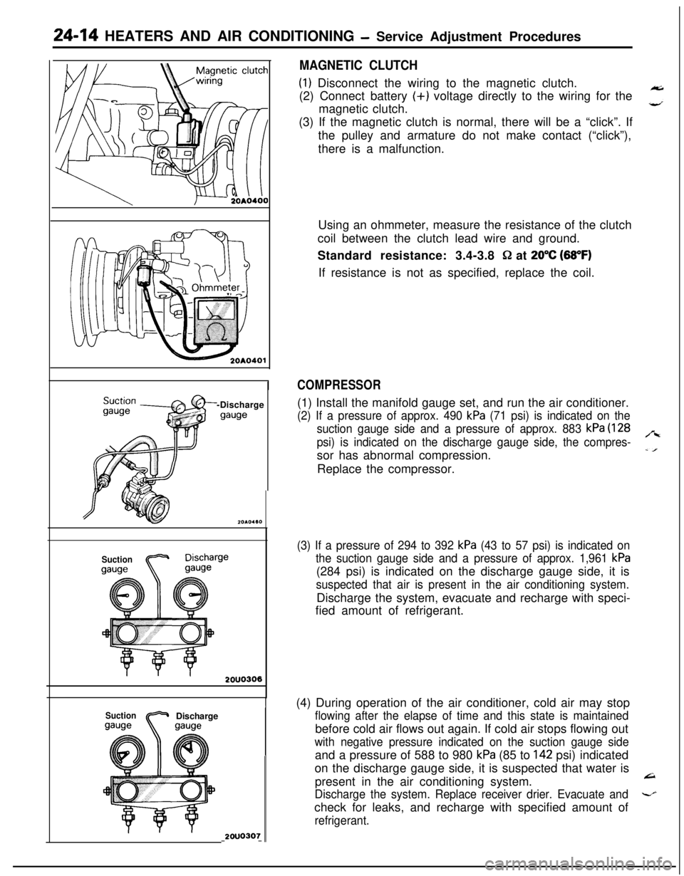
MAGNETIC CLUTCH(I) Disconnect the wiring to the magnetic clutch.
(2) Connect battery (+) voltage directly to the wiring for the
magnetic clutch.
,”(3) If the magnetic clutch is normal, there will be a “click”. If
the pulley and armature do not make contact (“click”),
there is a malfunction.
Using an ohmmeter, measure the resistance of the clutch
coil between the clutch lead wire and ground.
Standard resistance: 3.4-3.8
Q at 20°C (88°F)If resistance is not as specified, replace the coil.
COMPRESSOR(1) Install the manifold gauge set, and run the air conditioner.
(2) If a pressure of approx. 490 kPa (71 psi) is indicated on the
suction gauge side and a pressure of approx. 883
kPa (128
psi) is indicated on the discharge gauge side, the compres-
,“ssor has abnormal compression.
-IReplace the compressor.
(3) If a pressure of 294 to 392 kPa (43 to 57 psi) is indicated on
the suction gauge side and a pressure of approx. 1,961
kPa(284 psi) is indicated on the discharge gauge side, it is
suspected that air is present in the air conditioning system.Discharge the system, evacuate and recharge with speci-
fied amount of refrigerant.
(4) During operation of the air conditioner, cold air may stop
flowing after the elapse of time and this state is maintainedbefore cold air flows out again. If cold air stops flowing out
with negative pressure indicated on the suction gauge sideand a pressure of 588 to 980
kPa (85 to 142 psi) indicated
on the discharge gauge side, it is suspected that water is
present in the air conditioning system.
L=I
Discharge the system. Replace receiver drier. Evacuate and-check for leaks, and recharge with specified amount of
refrigerant.
Page 1163 of 1216
-.
HEATERS AND AIR CONDITIONING - Service Adjustment Procedures 241$19Oil collector can
2OAO464DISCHARGING SYSTEM
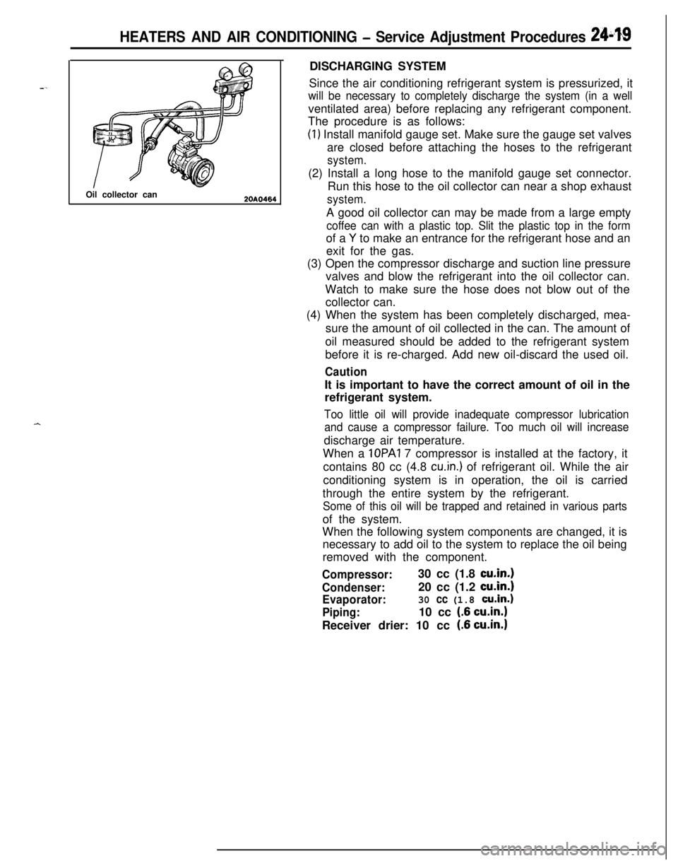
Since the air conditioning refrigerant system is pressurized, it
will be necessary to completely discharge the system (in a wellventilated area) before replacing any refrigerant component.
The procedure is as follows:
(1) Install manifold gauge set. Make sure the gauge set valves
are closed before attaching the hoses to the refrigerant
system.(2) Install a long hose to the manifold gauge set connector.
Run this hose to the oil collector can near a shop exhaust
system.A good oil collector can may be made from a large empty
coffee can with a plastic top. Slit the plastic top in the formof a
Y to make an entrance for the refrigerant hose and an
exit for the gas.
(3) Open the compressor discharge and suction line pressure
valves and blow the refrigerant into the oil collector can.
Watch to make sure the hose does not blow out of the
collector can.
(4) When the system has been completely discharged, mea-
sure the amount of oil collected in the can. The amount of
oil measured should be added to the refrigerant system
before it is re-charged. Add new oil-discard the used oil.
CautionIt is important to have the correct amount of oil in the
refrigerant system.
Too little oil will provide inadequate compressor lubrication
and cause a compressor failure. Too much oil will increasedischarge air temperature.
When a IOPAI 7 compressor is installed at the factory, it
contains 80 cc (4.8
cu.in.) of refrigerant oil. While the air
conditioning system is in operation, the oil is carried
through the entire system by the refrigerant.
Some of this oil will be trapped and retained in various partsof the system.
When the following system components are changed, it is
necessary to add oil to the system to replace the oil being
removed with the component.
Compressor:30 cc (1.8 cu.in.1
Condenser:20 cc (1.2 cu.in.1
Evaporator:30 cc (1.8 cu.in.)
Piping:10 cc (.6 cu.in.1Receiver drier: 10 cc
(.6 cu.in.1
Page 1164 of 1216
24-20 HEATERS AND AIR CONDITIONING - Service Adjustment Procedures
20A0465
20A0466
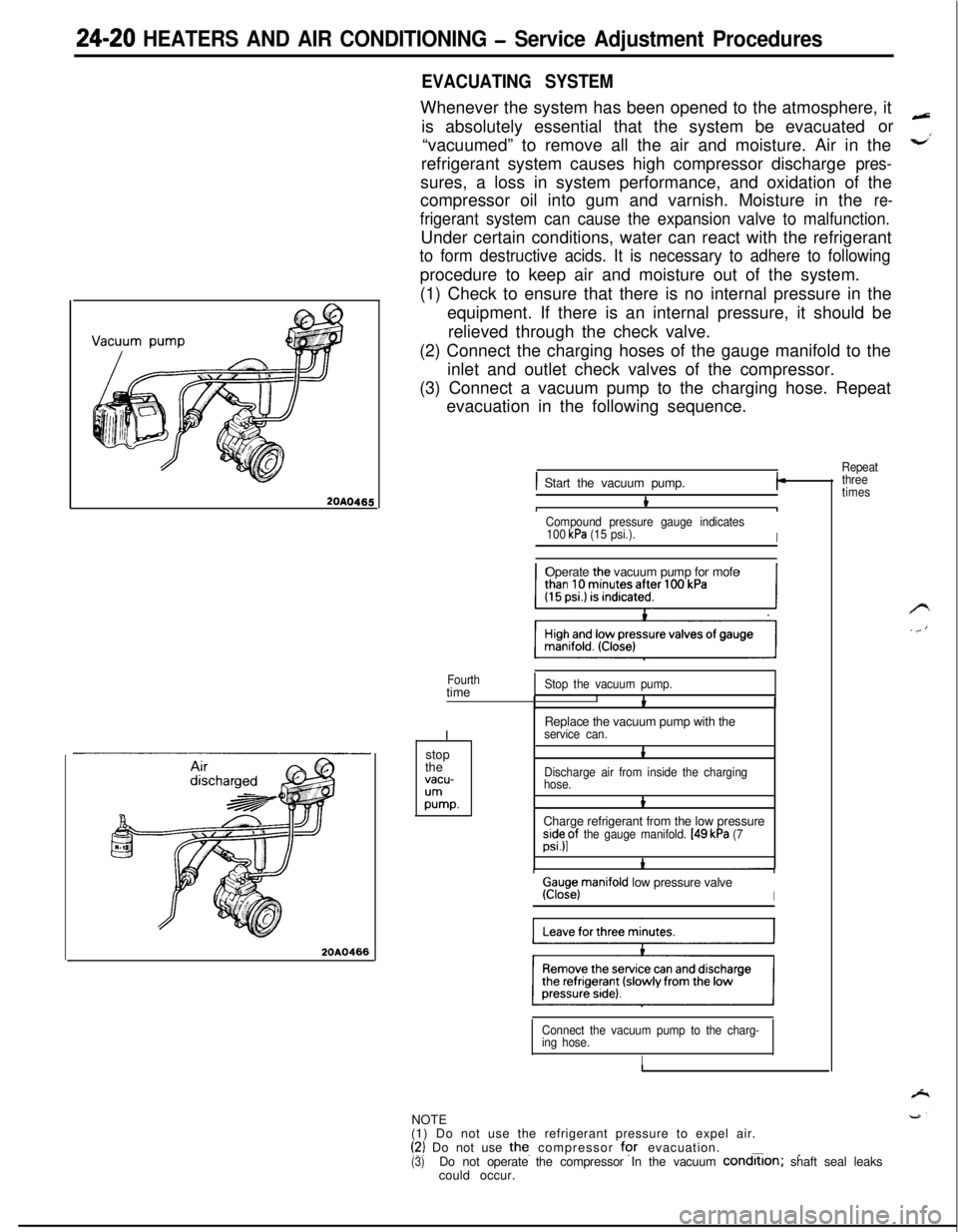
EVACUATING SYSTEMWhenever the system has been opened to the atmosphere, it
is absolutely essential that the system be evacuatedor
“vacuumed” to remove all the air and moisture. Air in the
refrigerant system causes high compressor discharge
pres-sures, a loss in system performance, and oxidation of the
compressor oil into gum and varnish. Moisture in the
re-
frigerant system can cause the expansion valve to malfunction.Under certain conditions, water can react with the refrigerant
to form destructive acids. It is necessary to adhere to followingprocedure to keep air and moisture out of the system.
(1) Check to ensure that there is no internal pressure in the
equipment. If there is an internal pressure, it should be
relieved through the check valve.
(2) Connect the charging hoses of the gauge manifold to the
inlet and outlet check valves of the compressor.
(3) Connect a vacuum pump to the charging hose. Repeat
evacuation in the following sequence.
Repeat
) Start the vacuum pump.I-
bIICompound pressure gauge indicates
100 kPa (15 psi.).IOperate the vacuum pump for mofe
Fourthtime
IStop the vacuum pump.IbReplace the vacuum pump with the
service can.stop
the
vacu-
;Ummp.
1
Discharge air from inside the charging
hose.
bCharge refrigerant from the low pressure
;s”;pf the gauge manifold. [49 kPa (7
Ga;iejmanifold low pressure valveI
Connect the vacuum pump to the charg-
ing hose.
INOTE
(1) Do not use the refrigerant pressure to expel air.
(‘2) Do not use the. compressor for evacuation.___(3)Do not operate the compressor In the vacuum condrtlon; shaft seal leaks
could occur.
three
times
Page 1168 of 1216
24-24 HEATERS AND AIR CONDITIONING - Service Adjustment Procedures
COMPRESSOR NOISENUFIABWhen investigating an air conditioning related noise, you must
first know the conditions when the noise occurs. These
conditions are: weather, vehicle speed, in gear or neutral,
engine temperature or any other special conditions.
Noises that develop during air conditioning operation can oftenbe misleading. For example: what sounds like a failed front
bearing or connecting rod, may be caused by loose bolts, nuts,mounting brackets, or a loose clutch assembly. Verify acces-
sory drive belt tension (power steering, or alternator).
Improper accessory drive belt tension can cause a misleading
noise when the compressor is engaged and little or no noise
when the compressor is disengaged.
Drive belts are speed sensitive. That is, at different engine
speeds, and depending upon belt tension, belts can develop
unusual noises that are often mistaken for mechanical prob-
lems within the compressor.
Adjustment Procedures
(1) Select a quiet area for testing. Duplicate conditions as
much as possible. Switch compressor on and off several
times to clearly identify compressor noise.
To duplicate high ambient conditions (high head pressure),restrict air flow through condenser. Install manifold gauge
set to make sure discharge pressure doesn’t exceed 2,070
kPa (300 psi).
(2) Tighten all compressor mounting bolts, clutch mounting
bolt, and compressor drive belt. Check to assure clutch coilis tight (no rotation or wobble).
(3) Check refrigerant hoses for rubbing or interference that cancause unusual noises.
(4) Check refrigerant charge (See “Charging the System”).
(5) Recheck compressor noise as in Step 1.
(6) If noise still exists, loosen compressor mounting bolts and
retorque. Repeat Step 1.
(7) If noise continues, replace compressor and repeat Step 1.
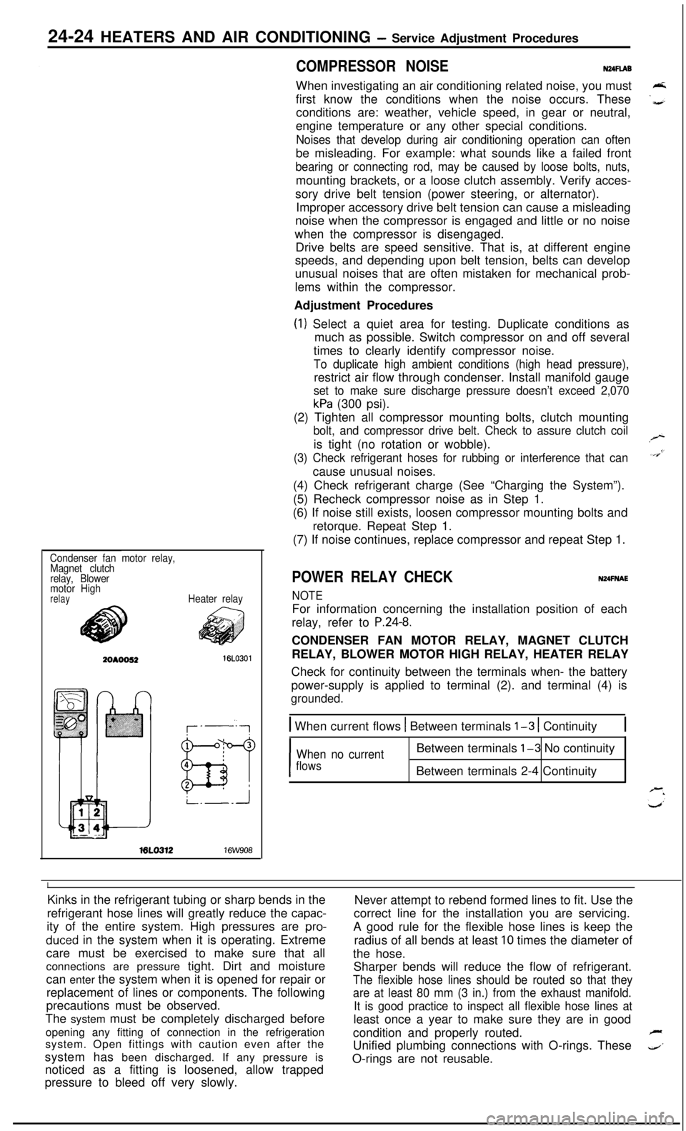
Condenser fan motor relay,
Magnet clutch
relay, Blower
motor High
relayHeater relayML0312
16W908
POWER RELAY CHECKNUFNAE
NOTEFor information concerning the installation position of each
relay, refer to
P.24-8.CONDENSER FAN MOTOR RELAY, MAGNET CLUTCH
RELAY, BLOWER MOTOR HIGH RELAY, HEATER RELAY
Check for continuity between the terminals when- the battery
power-supply is applied to terminal (2). and terminal (4) is
grounded.
1 When current flows 1 Between terminals l-3 1 Continuity1
I
When no currentBetween terminals l-3 No continuity
flowsBetween terminals 2-4 Continuity
IKinks in the refrigerant tubing or sharp bends in the
Never attempt to rebend formed lines to fit. Use the
refrigerant hose lines will greatly reduce the
capac-correct line for the installation you are servicing.
ity of the entire system. High pressures are
pro-A good rule for the flexible hose lines is keep the
duced in the system when it is operating. Extreme
radius of all bends at least 10 times the diameter of
care must be exercised to make sure that all
the hose.
connections are pressure tight. Dirt and moisture
Sharper bends will reduce the flow of refrigerant.
can enter the system when it is opened for repair or
The flexible hose lines should be routed so that theyreplacement of lines or components. The following
are at least 80 mm (3 in.) from the exhaust manifold.precautions must be observed.
It is good practice to inspect all flexible hose lines atThe system must be completely discharged before
least once a year to make sure they are in good
opening any fitting of connection in the refrigeration
condition and properly routed.
Fsystem. Open fittings with caution even after the
Unified plumbing connections with O-rings. These
4’system has been discharged. If any pressure is
noticed as a fitting is loosened, allow trappedO-rings are not reusable.
pressure to bleed off very slowly.