Page 894 of 1216

21-200AUTOMATIC TRANSAXLE - Troubleshooting
Trouble symptom
6. Improper rear
clutch pressure*,Probable causeRemedy
a.Malfunction of D-ring @of reara.Disassemble the rear clutch, check input shaft
clutch piston, retainer seal ring
@$I
and seal rings @and 0 of inputseal ring, retainer seal ring, piston
D ring, etc.
and replace broken or damaged parts.
shaft.
b.Functional malfunction of theb.Replace the valve body assembly.
valve body assembly7. Improper end
clutch pressure
a.Malfunction of seal ring @or thea.Disassemble the end clutch and check the oil
D-ring
@I and/or oil seal 0 of endseal or D-ring of the piston, seal ring of the
clutch.retainer, etc.; replace if there are cuts, scars,
scratches or damage.
b.Functional malfunction of theb.Replace the valve body assembly.
valve body assembly8. Improper
low-a.O-ring between valve body anda.Remove the valve body assembly and check to
reverse braketransaxle damaged or missingbe sure that the O-ring at the upper surface of
pressurethe upper valve body is not
missin7or dam-
aged; install or replace the O-ring inecessary.
b.Functional malfunction of theb.Replace the valve body assembly.
valve body assembly
c.Malfunction of the D-ring @of thec.Disassemble the transaxle itself and check the
low-reverse brake piston or theD-ring and O-ring for damage; replace if there
O-ring
@I of the retainerare cuts, scars, scratches or damage.9. Improper torque
a.Clogging or leaking of the oila.Repair or replace, as necessary, the coolerconverter pressure
cooler and/or pipingand/or piping.b.Malfunction of the torque conver-b.Replace the torque converter.ter
Page 903 of 1216

AUTOMATIC TRANSAXLE - service Adjustment Procedures21-209
09Pooi awith this range.
09POOll
TWO382
SERVICE ADJUSTMENT PROCEDURESN21FB6E
TRANSAXLE FLUID LEVEL INSPECTION1. Drive until the fluid temperature reaches the usual tem-
perature
[70-80°C (160- 18O”F)I.2. Place vehicle on level floor.
3. Move selector lever sequentially to every position to fill
torque converter and hydraulic circuit with fluid, then place
lever in “N” Neutral position.
4. Before removing dipstick, wipe all dirt from area around
dipstick. Then take out the dipstick and check the conditionof the fluid.
The transaxle should be overhauled under the following
conditions.l If there is a “burning” odor.
l If the fluid color has become noticeably blacker.
lIf there is a noticeably great amount of metal particles inthe fluid.
5.Check to see if fluid level is in “HOT” range on dipstick. If
fluid level is low, add automatic transaxle fluid until level
reaches “HOT” range.
Transaxle fluid: MOPAR ATF PLUS (Automatic trans-
mission fluid type 7176) or Dia ATF SPor equivalent
Low fluid level can cause a variety of conditions
becaljse it
allows pump to take in air along with fluid. Air trapped in
hydraulic circuit forms bubbles which make fluid spongy.
Therefore, pressures will be erratic, causing delayed shift,
slippy clutch and brakes, etc.
Improper filling can also raise fluid level too high. When
transaxle has too much fluid, gears churn up foam and
cause the same conditions which occur with low fluid level,
resulting in accelerated deterioration of automatic transaxle
fluid.In either case, air bubbles can cause overheating, fluid
oxidation, which can interfere with normal valve, clutch,
and servo operation.Foaming can also result in fluid
escaping from transaxle vent where it may be mistaken for
a leak.6. Be sure to examine fluid on dipstick closely.
TRANSAXLE FLUID REPLACEMENTN21FCBAaRefer to GROUP O-Maintenance Service.
TRANSFER OIL LEVEL INSPECTIONNZlFXAATransfer oil level inspection is the same as for the manual
transaxle transfer.
Refer to GROUP
22-Service Adjustment Procedures.
TRANSFER OIL REPLACEMENTNZlFYAFaTransfer oil replacement is the same as for manual transaxle
transfer.Refer to GROUP
22-Service Adjustment Procedures.
Page 907 of 1216

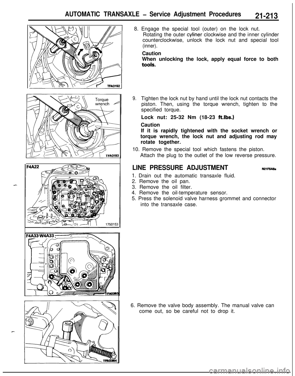
AUTOMATIC TRANSAXLE - Service Adjustment Procedures21-2138. Engage the special tool (outer) on the lock nut.
Rotating the outer cyliner clockwise and the inner cylinder
counterclockwise, unlock the lock nut and special tool
(inner).Caution
When unlocking the lock, apply equal force to bothtools.
9.Tighten the lock nut by hand until the lock nut contacts the
piston. Then, using the torque wrench, tighten to the
specified torque.
Lock nut: 25-32 Nm (18-23 ft.lbs.)
Caution
If it is rapidly tightened with the socket wrench or
torque wrench, the lock nut and adjusting rod may
rotate together.
10. Remove the special tool which fastens the piston.
Attach the plug to the outlet of the low reverse pressure.
LINE PRESSURE ADJUSTMENTN2lFSABl
1. Drain out the automatic transaxle fluid.
2. Remove the oil pan.
3. Remove the oil filter.
4. Remove the oil-temperature sensor.
5. Press the solenoid valve harness grommet and connector
into the transaxle case.
6. Remove the valve body assembly. The manual valve can
come out, so be careful not to drop it.
Page 908 of 1216

21-214AUTOMATIC TRANSAXLE - Service Adjustment Procedures
'50157
F4
1
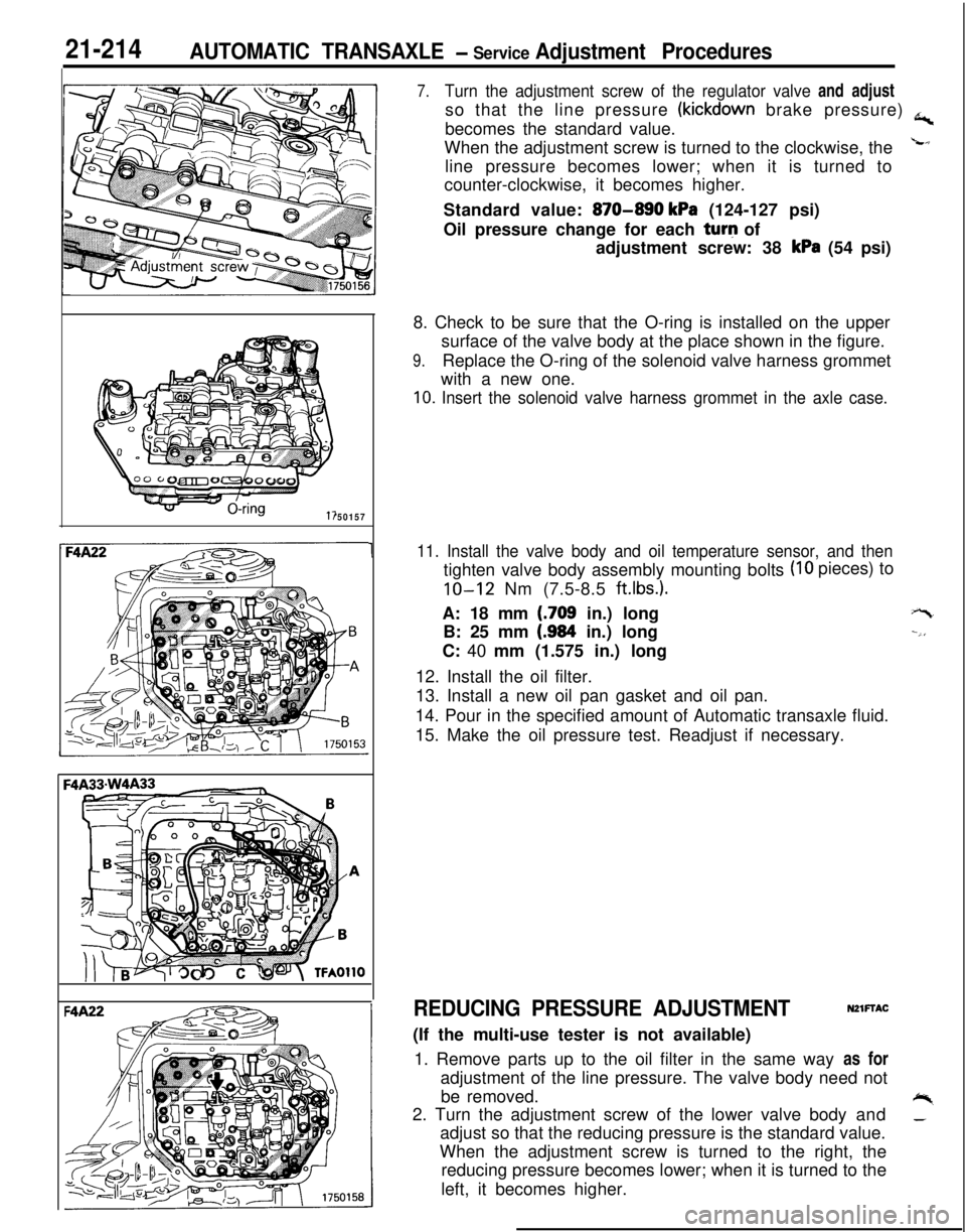
7.Turn the adjustment screw of the regulator valve and adjustso that the line pressure
(kickdown brake pressure) a,becomes the standard value.
When the adjustment screw is turned to the clockwise, the
Lline pressure becomes lower; when it is turned to
counter-clockwise, it becomes higher.
Standard value:
870-890 kPa (124-127 psi)
Oil pressure change for each turq of
adjustment screw: 38
kPa (54 psi)
8. Check to be sure that the O-ring is installed on the upper
surface of the valve body at the place shown in the figure.
9.Replace the O-ring of the solenoid valve harness grommet
with a new one.
10. Insert the solenoid valve harness grommet in the axle case.
11. Install the valve body and oil temperature sensor, and then
(IO pieces) to
tighten valve body assembly mounting bolts
IO-12 Nm (7.5-8.5 ft.lbs.).A: 18 mm
(.709 in.) long
B: 25 mm
(.984 in.) long
C: 40 mm (1.575 in.) long
12. Install the oil filter.
13. Install a new oil pan gasket and oil pan.
14. Pour in the specified amount of Automatic transaxle fluid.
15. Make the oil pressure test. Readjust if necessary.
+-t
--,,
REDUCING PRESSURE ADJUSTMENTNZlFTAC(If the multi-use tester is not available)
1. Remove parts up to the oil filter in the same way as for
adjustment of the line pressure. The valve body need not
be removed.
+%2. Turn the adjustment screw of the lower valve body and_adjust so that the reducing pressure is the standard value.
When the adjustment screw is turned to the right, the
reducing pressure becomes lower; when it is turned to the
left, it becomes higher.
Page 909 of 1216

AUTOMATIC TRANSAXLE - Service Adjustment Piocedures21-215
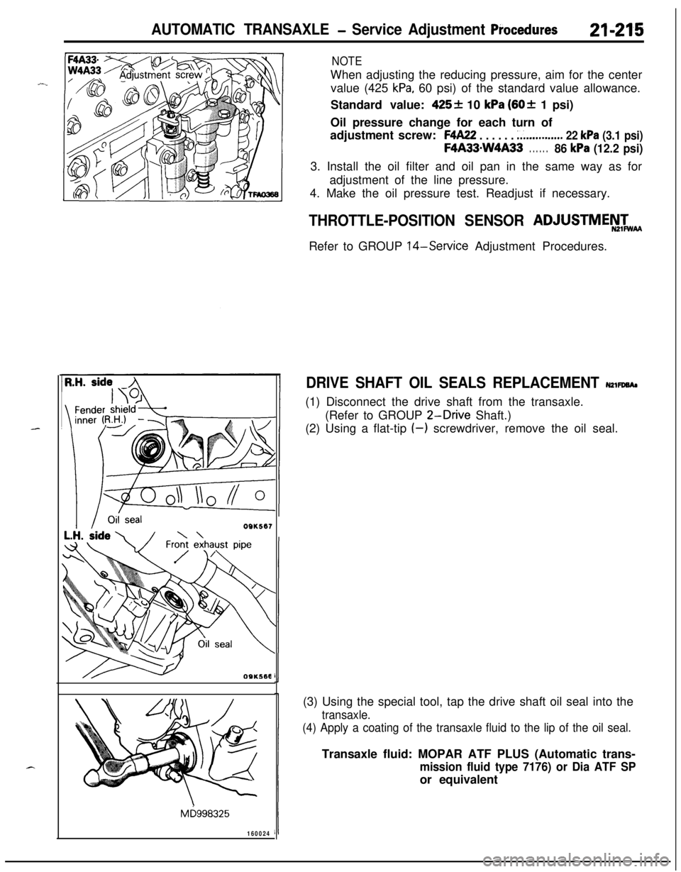
NOTEWhen adjusting the reducing pressure, aim for the center
value (425
kPa, 60 psi) of the standard value allowance.
Standard value:
425+ 10 kPa (60+ 1 psi)
Oil pressure change for each turn of
adjustment screw:
F4A22 . . . . . . ;...........,.. 22 kPa (3.1 psi)
F4A33mW4A33. . . . . .86 kPa (12.2 psi)3. Install the oil filter and oil pan in the same way as for
adjustment of the line pressure.
4. Make the oil pressure test. Readjust if necessary.
OQK567
OSKS68
Mb998325
160024
THROTTLE-POSITION SENSOR ADJUSTMEN&
Refer to GROUP
14-Service Adjustment Procedures.
DRIVE SHAFT OIL SEALS REPLACEMENT NZWWA,(1) Disconnect the drive shaft from the transaxle.
(Refer to GROUP
2-Drive Shaft.)
(2) Using a flat-tip
(-) screwdriver, remove the oil seal.
(3) Using the special tool, tap the drive shaft oil seal into the
transaxle.
(4) Apply a coating of the transaxle fluid to the lip of the oil seal.Transaxle fluid: MOPAR ATF PLUS (Automatic trans-
mission fluid type 7176) or Dia ATF SPor equivalent
Page 982 of 1216
21-288 AUTOMATIC TRANSAXLE - Transaxle Assemblv 34. Install the special tool on the center support, install new
O-rings (2 locations) pressing them into the transaxle case.Cautiona1. Apply ATF to the O-ring and align the oil hole.
L2. Install so the waved spring is aligned.
35. Install the snap ring.
36. Measure the end play of the low reverse brake with a
thickness gauge and select and adjust the pressure plate soit is within the standard value.
Standard value:
l.O- 1.2 mm (.039-.047 in.)v37. Install the air exhaust plug and then install the plug.
Air exhaust plug:
30-35 Nm (22-25 ft.lbs.)38. Install the anchor rod.
‘I
Page 1018 of 1216
21-324AUTOMATIC TRANSAXLE - Valve Body
VALVE BODY
DISASSEMBLY AND REASSEMBLYViewed from A
NZlLOAK
-0 - -
8
TFA0523
Disassembly steps
1. Manual valve
l +2. Pressure control solenoid valvel +3. Damper clutch control solenoid v
l +4. Shift control solenoid valve “A”
l +5. Shift control solenoid valve “B”6. Clamp
7. Valve stopper
8. N-D control sleeve
9. N-D control valve
l + 10. Lower valve body sub assembly11. Lower separating plate12.Nut13.Jet
l + 14. Relief spring
l + 15. Steel ballH 16. Oil filterW 17. Upper valve body sub assemblyWI
18. Steel ball
H 19. Teflon balll 420.N-Delate
NOTE(1) Reverse the disassembly procedures to reassemble.(2) l 4 : Refer to “Service Points of Reassembly”.
21. Block22. Upper separating plate
23. Intermediate plate
Page 1044 of 1216

22-6WHEELS AND TIRES - Wheel and Tire
INSTRUCTIONS FOR ALUMINUM TYPE
WHEELSUzzGfM
1. Aluminum is vulnerable to alkalies. If a vehicle
washing detergent has been used, or salt from
sea water or road chemicals has adhered, washthe vehicle as soon as possible. After washing
the vehicle, apply body or wheel wax to the
aluminum type wheels to prevent corrosion.
2. When cleaning the vehicle with steam, do not
direct steam onto the aluminum type wheels.
When tightening nuts for aluminum type
wheels, particularly observe the following:
(1) Clean the hub surface of aluminum type
wheels.(2) After finger-tightening wheel nuts, tighten
them to specifications.
(3) Do not use an impact wrench or push the
wrench by foot to tighten the wheel nuts.
(4) Do not apply oil to the threaded portions.
INSTRUCTIONS FOR TIRE CHAINS AND
SNOW TIRESNZZGGAA
1.Use tire chains only on front wheels. Do not usetire chains on rear wheels.
2. When using snow tires, use them on all four
wheels for maneuverability and safety.
INSTRUCTIONS FOR COMPACT SPARE
TIRE;c.1. The compact spare tire is designed to. save
space in the luggage compartment, and its
L’lighter weight makes it easier to use if a fiat tire
occurs.
2.The following instructions for the compact sparetire should be observed.
(1) Check the inflation pressure after installing
the spare, and adjust to the specified pres-
sure.(2) Avoid driving through automatic car washes
and over obstacles that could possibly dam-
age the vehicle’s undercarriage. Because
the tire is smaller than the original tire, car
ground clearance is slightly reduced.
(3) The compact spare tire should not be used
on any other wheels, nor should standard
tires, snow tires, wheel covers or trim rings
be used with the compact spare wheel. If
such use is attempted, damage to these
items or other vehicle components may
occur.