Page 923 of 1216

AUTOMATIC TRANSAXLE - Transaxle Assembly B-229
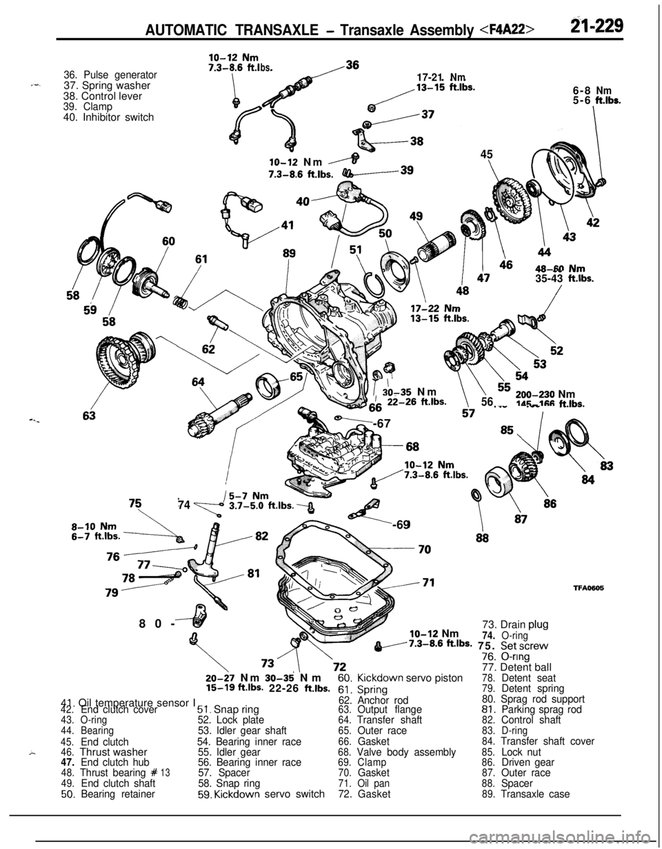
36. Pulse generator37. Spring washer
38. Control lever
39. Clamp40. Inhibitor switch
ln ~19 Nm
bs.17-21Nm6-8
Nm5-6ft.lbs.
-I
45
6IO-12 Nm
,----IT7.3-8.6
ftlbs.-3980-
46AR-M N~JTV -- .-.35-43 ft.iIbs.
b??io r 20-35 Nm\h\\iii-26 ft.lbs.
-,i7 ._.. .__ ._..v.-6756,,,-e30 Nmldr;-11% f-klhs.
I
,
747%!%t.lbs.3<-69
glo-12 Nm73. Drain plu!
74.O-ringv7.3-8.6 ftJbS- 75. Setscrev-^^V/8. u-nng
77. Detent ball
TFA050520-27 Nm
30-35' Nm60.Kickdown servo piston78.Detent seat15-16 ft.lbs- 22-26 ftlbs.61.Spring79.Detent spring
41. Oil temperature sensor I62. Anchor rod80. Sprag rod support42.End clutch cover51. Snap ring63.Output flange81.Parking sprag rod43.O-ring52. Lock plate64.Transfer shaft82.Control shaft44.Bearing53. Idler gear shaft65.Outer race83.D-ring
45.
End clutch54. Bearing inner race66.Gasket84.Transfer shaft cover
46.Thrust washer55. Idler gear68.Valve body assembly85.Lock nut47.End clutch hub56. Bearing inner race69.Clamp86.Driven gear48.Thrust bearing #1357. Spacer70.Gasket87.Outer race49.End clutch shaft58. Snap ring71.Oil pan88.Spacer50.Bearing retainer59. Kickdown servo switch72.Gasket89.Transaxle case
Page 924 of 1216

-2.rt-2-30~~ AUTOMATIC TRANSAXLE - Transaxle Assembly
;haft1770083
DISASSEMBLYNZlLEAl1. Clean away any sand, mud, etc. adhered around the
.+
transaxle..
2.
Place the transaxle assembly on the workbench with the oil--’
pan down.
3. Remove the torque converter.
4. Measuring input shaft end play before disassembly will
usually indicate when a thrust washer change is required
(except when major parts are replaced). Thrust washers arelocated between reaction shaft support and rear clutch
retainer, and between reaction shaft support and front
clutch retainer.
Mount a dial indicator to converter housing with the Dial
Indicator Support. Make sure that the indicator plunger is
seated against end of input shaft.
When checking end play, pull out or push in the input shaft
with pliers. Be careful not to scratch the input shaft. Record
indicator reading for reference when reassembling transax-
le.5. Remove the pulse generator “A” and “B”
6. Remove manual control lever, then remove inhibitor
switch.
7. Remove snap ring then remove
kickdown servo switch.
Page 925 of 1216
AUTOMATIC TRANSAXLE - Transaxle Assembly 21-237
sensor17504288. Remove the oil pan and gasket.
9. Remove the oil filter from the valve body.
10. Remove the oil-temperature sensor installation bolt; then,
after removal from the bracket, pull out from the connector
side.11. Insert the solenoid valve harness grommet and connector
into the transaxle case.
12. Remove 10 bolts and remove valve body.
13. Remove the end clutch cover mounting bolt the cover
holder, and the end clutch cover.
Page 927 of 1216
AUTOMATIC TRANSAXLE - Transaxle Assembly 21-233
19. Remove 6 bolts, and attach the special tools and remove oilpump assembly.
20. Remove the spacer and the differential assembly.
21. Remove the thrust washer
#I22. Pull up the input shaft, and then remove the front clutch
assembly and the rear clutch assembly together.
23. Remove the thrust bearing
#6.
Page 947 of 1216
AUTOMATIC TRANSAXLE - Transaxle Assembly 21-253Thrust race
53. If end play which was measured and recorded at disassem-
bly is not standard value, adjust end play to specification byselecting thrust race
#3.Standard value
:0.3-1.0 mm (.012-.040 in.)
54. Attach the reused thrust washer
#I, or the one selected in
step 51 to the front clutch by using petrolatum.
55. Install special tool to the case.
56. Attach the reused thrust race
#3 or the one selected in
step 53 to the oil pump by using petrolatum.
57. Install new oil pump gasket and the oil pump assembly.
Page 948 of 1216

AUTOMATIC TRANSAXLE - Transaxle Assemblv
Solder
220004858. Install new O-ring in groove of oil pump housing and apply
automatic transmission fluid lightly to outside surface of
O-ring.e59. Install oil pump assembly by tightening six bolts evenly.
i-When installing this oil pump assembly, be careful that
thrust washer will not drop.
60. Check input shaft end play. Readjust if necessary (see step
53).Standard value
: 0.3-1.0 mm (.012-,040 in.)
61, Apply solder [length approx. 10 mm (40 in.) and diameter
1.6 mm (.06 in.) to the differential assembly at the locationsshown in the illustration.
“I
-4--J62. Install the converter housing without gasket.
Caution
Don’t reuse the rubber coated metal gasket which has
been used once.
63. Tighten bolts to specification.
64. Loosen the bolts and remove the converter housing in
order to remove the pieces of solder. If the solder is not
broken, carry out the work in steps (61) to (64) with large
diameter solder.
65. Using a micrometer, measure the thickness of the flattned
solder.Select the spacer in the following manner according to
measurement.Add the thickness
[0.38 mm (015 in.)] of the rubber coated
metal gasket and the end play
LO-O.1 5 mm (O-.006 in.)] ofi4the differential case to the measurement
(T). Select a -spacer which is in the calculated range, In other words,
select a spacer whose thickness is in the range of n+ 0.38mm
(.015 in.)] to [T+ 0.38 mm (.015 in.) - 0.15 mm (.006
in.)].
Page 951 of 1216

AUTOMATIC TRANSAXLE - Transaxle Assembly 21-257
7750157
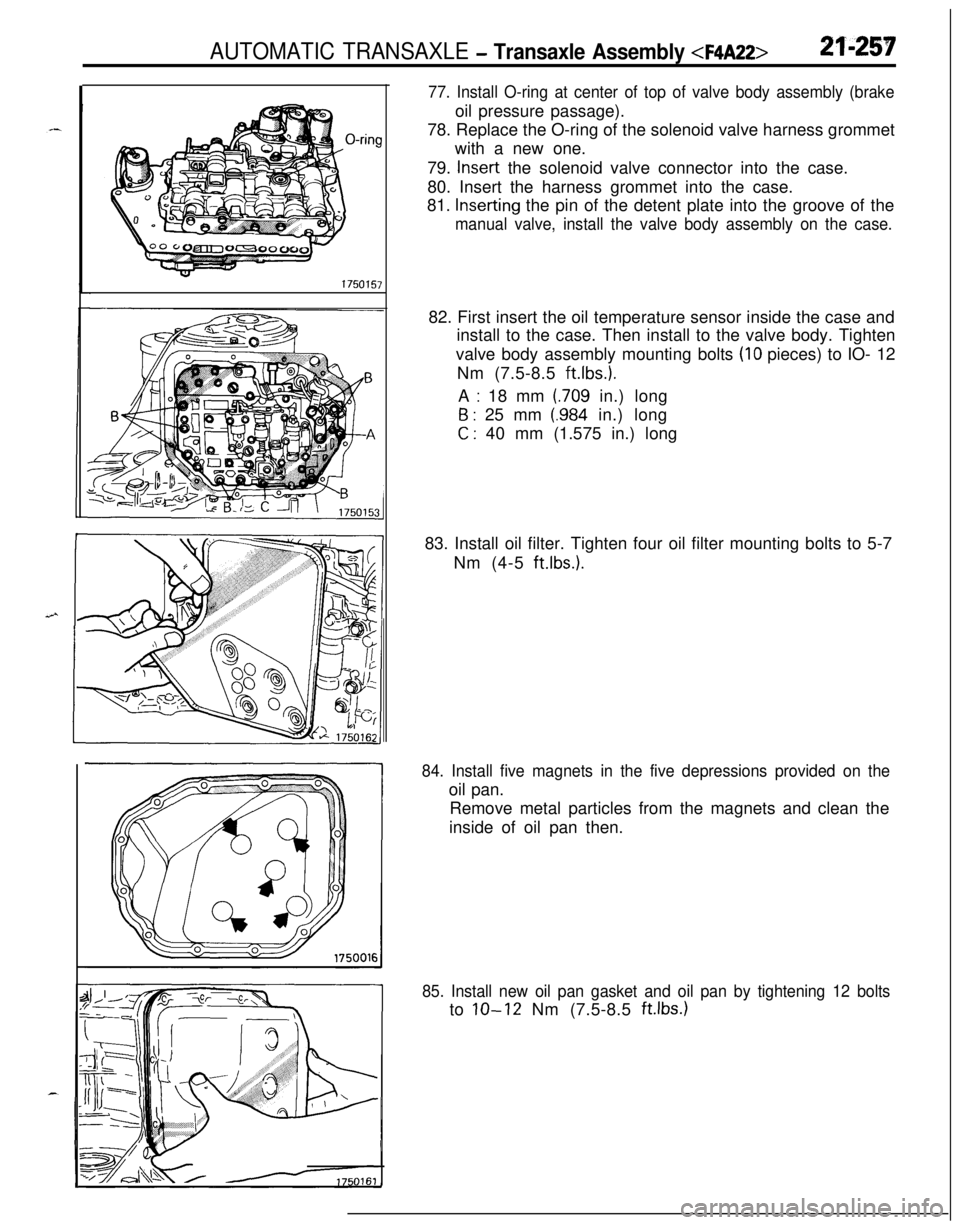
77. Install O-ring at center of top of valve body assembly (brakeoil pressure passage).
78. Replace the O-ring of the solenoid valve harness grommet
with a new one.
79.
Insert the solenoid valve connector into the case.
80. Insert the harness grommet into the case.
81.
Inserting the pin of the detent plate into the groove of the
manual valve, install the valve body assembly on the case.82. First insert the oil temperature sensor inside the case and
install to the case. Then install to the valve body. Tighten
valve body assembly mounting bolts
(IO pieces) to IO- 12
Nm (7.5-8.5
ft.lbs.).A
: 18 mm (709 in.) long
6 : 25 mm (.984 in.) long
C : 40 mm (1.575 in.) long
83. Install oil filter. Tighten four oil filter mounting bolts to 5-7
Nm (4-5
ft.lbs.1.
84. Install five magnets in the five depressions provided on theoil pan.
Remove metal particles from the magnets and clean the
inside of oil pan then.
85. Install new oil pan gasket and oil pan by tightening 12 boltsto
lo-12 Nm (7.5-8.5 ft.lbs.1
Page 952 of 1216
AUTOMATIC TRANSAXLE - Transaxle Assembly 86. Install a new D-ring to the kickdown servo switch; then
press into the case and secure it by using a snap ring.
87. Install inhibitor switch and manual lever.
Adjust inhibitor switch. (Refer to
P.21-211.)88. Install the pulse generator A and
B.89. After applying automatic transaxle fluid to outside surface
of oil pump-side cylindrical portion of torque converter,
install torque converter carefully so as not to damage oil
seal lip. Make certain that torque converter is in mesh with
oil pump drive gear.
90. Measure distance between ring gear end and converter
housing end. Torque converter has been properly installed
when measurement is about 12 mm
(.47 in.).
91. Using special tools, drive two drive shaft oil seals into
transaxle case.