Page 907 of 1216
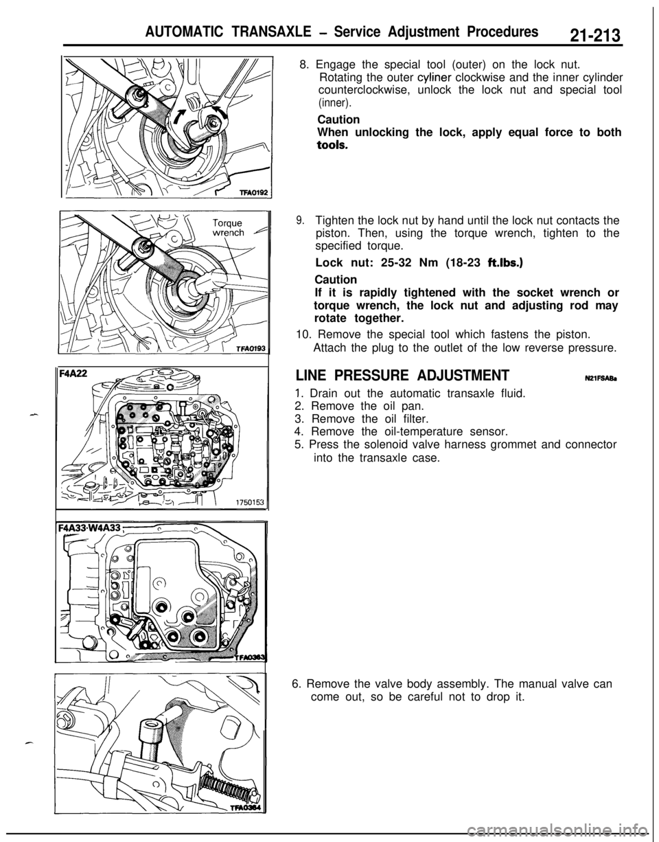
AUTOMATIC TRANSAXLE - Service Adjustment Procedures21-2138. Engage the special tool (outer) on the lock nut.
Rotating the outer cyliner clockwise and the inner cylinder
counterclockwise, unlock the lock nut and special tool
(inner).Caution
When unlocking the lock, apply equal force to bothtools.
9.Tighten the lock nut by hand until the lock nut contacts the
piston. Then, using the torque wrench, tighten to the
specified torque.
Lock nut: 25-32 Nm (18-23 ft.lbs.)
Caution
If it is rapidly tightened with the socket wrench or
torque wrench, the lock nut and adjusting rod may
rotate together.
10. Remove the special tool which fastens the piston.
Attach the plug to the outlet of the low reverse pressure.
LINE PRESSURE ADJUSTMENTN2lFSABl
1. Drain out the automatic transaxle fluid.
2. Remove the oil pan.
3. Remove the oil filter.
4. Remove the oil-temperature sensor.
5. Press the solenoid valve harness grommet and connector
into the transaxle case.
6. Remove the valve body assembly. The manual valve can
come out, so be careful not to drop it.
Page 908 of 1216
21-214AUTOMATIC TRANSAXLE - Service Adjustment Procedures
'50157
F4
1
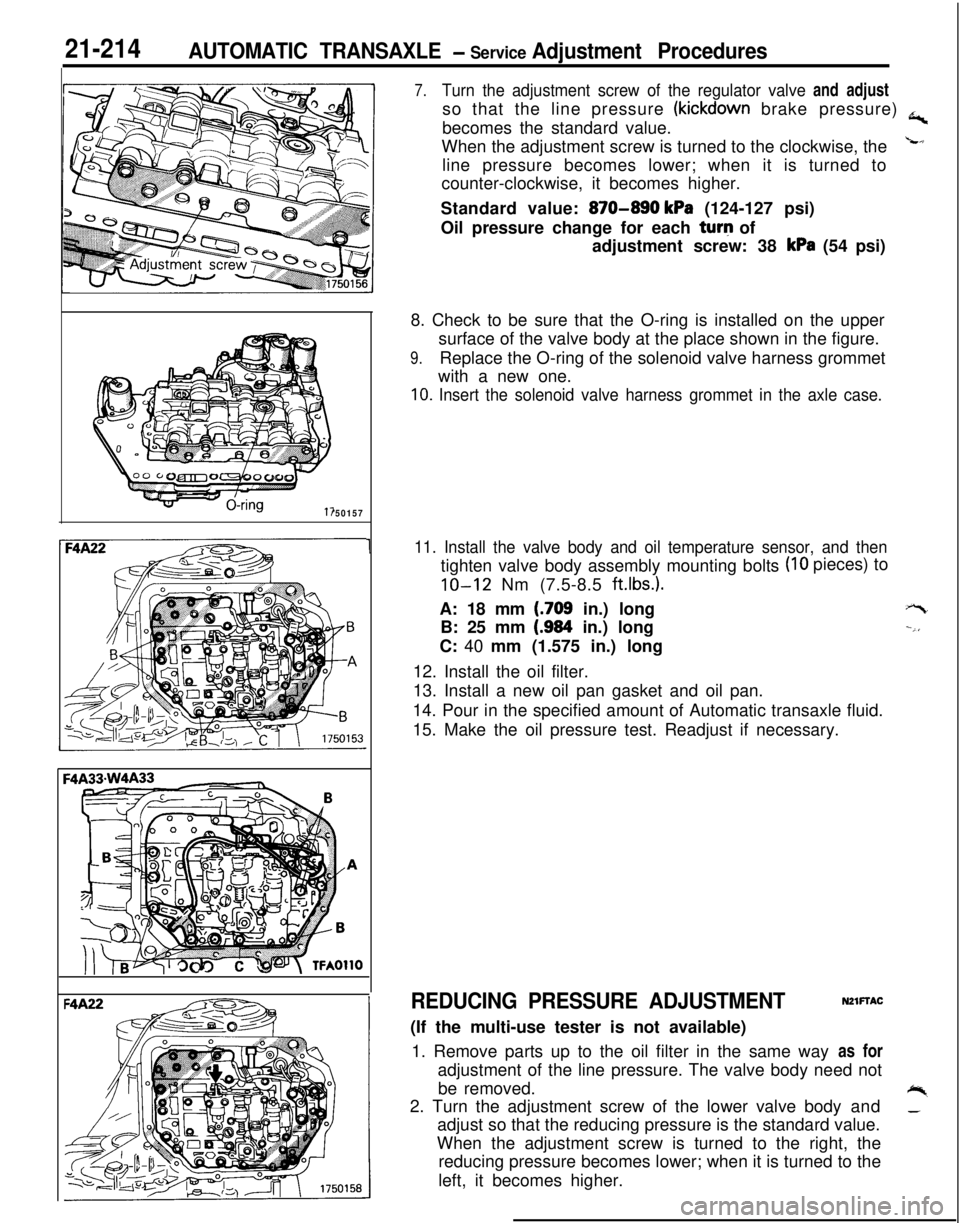
7.Turn the adjustment screw of the regulator valve and adjustso that the line pressure
(kickdown brake pressure) a,becomes the standard value.
When the adjustment screw is turned to the clockwise, the
Lline pressure becomes lower; when it is turned to
counter-clockwise, it becomes higher.
Standard value:
870-890 kPa (124-127 psi)
Oil pressure change for each turq of
adjustment screw: 38
kPa (54 psi)
8. Check to be sure that the O-ring is installed on the upper
surface of the valve body at the place shown in the figure.
9.Replace the O-ring of the solenoid valve harness grommet
with a new one.
10. Insert the solenoid valve harness grommet in the axle case.
11. Install the valve body and oil temperature sensor, and then
(IO pieces) to
tighten valve body assembly mounting bolts
IO-12 Nm (7.5-8.5 ft.lbs.).A: 18 mm
(.709 in.) long
B: 25 mm
(.984 in.) long
C: 40 mm (1.575 in.) long
12. Install the oil filter.
13. Install a new oil pan gasket and oil pan.
14. Pour in the specified amount of Automatic transaxle fluid.
15. Make the oil pressure test. Readjust if necessary.
+-t
--,,
REDUCING PRESSURE ADJUSTMENTNZlFTAC(If the multi-use tester is not available)
1. Remove parts up to the oil filter in the same way as for
adjustment of the line pressure. The valve body need not
be removed.
+%2. Turn the adjustment screw of the lower valve body and_adjust so that the reducing pressure is the standard value.
When the adjustment screw is turned to the right, the
reducing pressure becomes lower; when it is turned to the
left, it becomes higher.
Page 909 of 1216
AUTOMATIC TRANSAXLE - Service Adjustment Piocedures21-215
NOTEWhen adjusting the reducing pressure, aim for the center
value (425
kPa, 60 psi) of the standard value allowance.
Standard value:
425+ 10 kPa (60+ 1 psi)
Oil pressure change for each turn of
adjustment screw:
F4A22 . . . . . . ;...........,.. 22 kPa (3.1 psi)
F4A33mW4A33. . . . . .86 kPa (12.2 psi)3. Install the oil filter and oil pan in the same way as for
adjustment of the line pressure.
4. Make the oil pressure test. Readjust if necessary.
OQK567
OSKS68
Mb998325
160024
THROTTLE-POSITION SENSOR ADJUSTMEN&
Refer to GROUP
14-Service Adjustment Procedures.
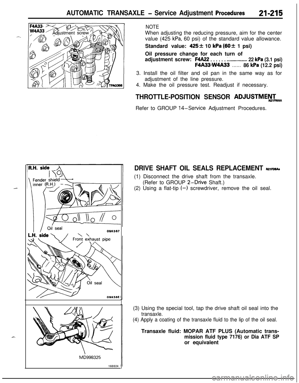
DRIVE SHAFT OIL SEALS REPLACEMENT NZWWA,(1) Disconnect the drive shaft from the transaxle.
(Refer to GROUP
2-Drive Shaft.)
(2) Using a flat-tip
(-) screwdriver, remove the oil seal.
(3) Using the special tool, tap the drive shaft oil seal into the
transaxle.
(4) Apply a coating of the transaxle fluid to the lip of the oil seal.Transaxle fluid: MOPAR ATF PLUS (Automatic trans-
mission fluid type 7176) or Dia ATF SPor equivalent
Page 917 of 1216
AUTOMATIC TRANSAXLE - Transaxle Oil Cooler Hoses2 I*-223TRANSAXLE OIL COOLER HOSES
NZlSA-A
- REMOVAL AND INSTALLATION
3-5
Nm2-4 ftlbs.
4-6
Nm3-4 ftlbs.
09AOO41
Removal steps
1. Hose clamp
4*2. Oil cooler hose assembly
NOTE(1) Reverse the removal procedures to reinstall.(2) 4e : Refer to “Service Points of Removal”.
SERVICE POINTS OF REMOVALNZISSAD2. REMOVAL OF OIL COOLER HOSE ASSEMBLY
Caution
1. Take care not to spill the transaxle fluid when
removing components.
2. After removing the oil cooler hose assembly, plug
so that foreign materials cannot enter the transaxle.
INSPECTIONm1scAFl Check the hose for crack, damage and clog.
l Check for rusted or clogged radiator oil cooler.
Page 918 of 1216
21-224AUTOMATIC TRANSAXLE - Transaxle Oil Cooler
TRANSAXLE OIL COOLER
REMOVAL AND INSTALLATION
OQA01691
30-35 Nm
22-25 ft.lbs.
/I1’
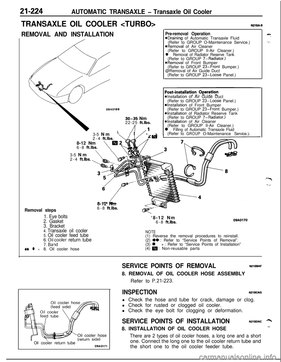
Removal steps
1. Eye bolts
2. Gasket3-5 Nm
‘\/I/ --
2-4
ftlbs.8-12 Nm
m26-8 ft.lbs.\\
N21SA-B
Pre-removal OperationeDraining of Automatic Transaxle Fluid
(Refer to GROUP O-Maintenance Service.)
@Removal of Air Cleaner
(Refer to GROUP II-Air Cleaner.)
l Removal of Radiator Reserve Tank(Refer to GROUP 7-Radiator.)
@Removal of Front Bumper
(Refer to GROUP 23-Front Bumper.)
@Removal of Air Guide Duct
(Refer to GROUP
23-Loose Panel.)
*Installation of Air Guide Duct
(Refer to GROUP 23-Loose Panel.)*Installation of Front Bumper
(Refer to GROUP 23-Front Bumper.)@Installation of Radiator Reserve Tank
(Refer to GROUP 7-Radiator.)
*Installation of Air Cleaner
(Refer to GROUP II-Air Cleaner.)
l Filling of Automatic Transaxle Fluid(Refer toGROUPO-MaintenanceService.)3-5 Nm
2-4
ftlbs.8-12 Nm
6-8
ft.lbs.‘8-12 Nm
6-8
ftlbs.OBAOl703. Bracket
4. Transaxle oil cooler5. Oil cooler feed tubeNOTE(1) Reverse the removal procedures to reinstall.
7: ~i&~oler return tube(2) ++ : Refer to “Service Points of Removal”.
(3) l + : Refer to “Service Points of Installation”
+e l +8. Oil cooler hose(4) m : Non-reusable parts
Oil cooler hose
Oilcoolerreturn tube09A0171
&.
-=-.
SERVICE POINTS OF REMOVALNZlSBAF8. REMOVAL OF OIL COOLER HOSE ASSEMBLY
Refer to
P.21-223.
INSPECTIONN2lSCAGl Check the hose and tube for crack, damage or clog.
l Check for rusted or clogged oil cooler.
l Check the eye bolt for clogging or deformation.
SERVICE POINTS OF INSTALLATIONN2lSDAC ‘-+8. INSTALLATION OF OIL COOLER HOSE_
There are 2 types of oil cooler hoses, a long one and a shortone. Connect the long one to the oil cooler return tube and
the short one to the oil cooler feeder tube.
Page 919 of 1216
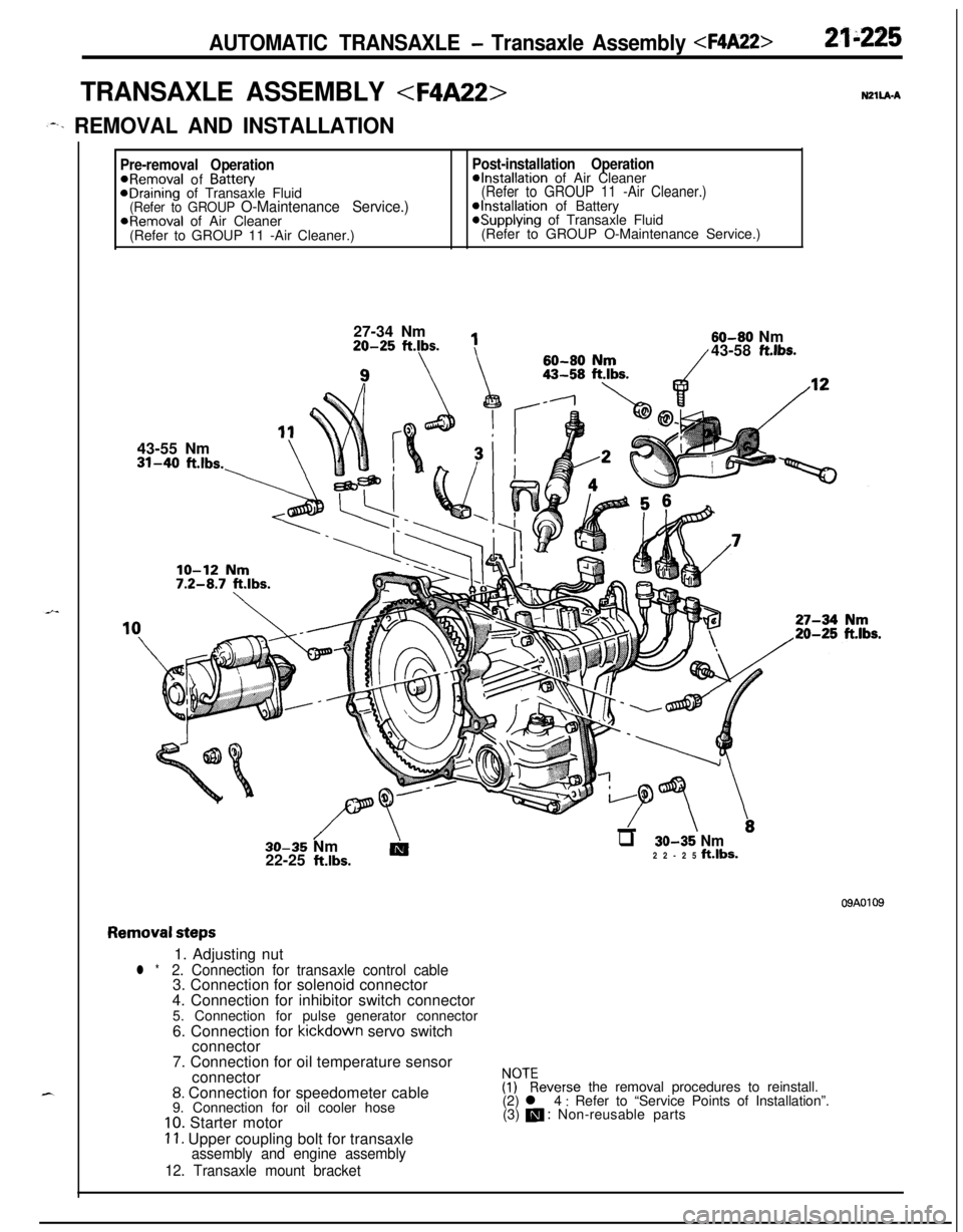
AUTOMATIC TRANSAXLE - Transaxle Assembly 21"225
TRANSAXLE ASSEMBLY N2ll.A.A
,--. REMOVAL AND INSTALLATION
Pre-removal OperationPost-installation Operation@Removal of Battew@Installation of Air CleaneraDraining of Transaxle Fluid(Refer to GROUP 11 -Air Cleaner.)(Refer to GROUP O-Maintenance Service.)@Installation of BatteryaRemoval of Air Cleaner*Supplying of Transaxle Fluid
(Refer to GROUP 11 -Air Cleaner.)(Refer to GROUP O-Maintenance Service.)
27-34 Nm20-25
ftlbs.
1143-55 Nm31-40
ft.lbs.-\60-80
flrn60-80 Nm/43-58 ft.lbs.
//\-LTT \.30-35 Nm
AIq 30-35 Nm22-25 klbs.22-25 ft.lbs.
09A0109
Removal steps1. Adjusting nut
l *2. Connection for transaxle control cable3. Connection for solenoid connector
4. Connection for inhibitor switch connector
5. Connection for pulse generator connector
6. Connection for kickdown servo switch
connector
7. Connection for oil temperature sensor
connector
8. Connection for speedometer cable
9. Connection for oil cooler hose
10. Starter motor
11. Upper coupling bolt for transaxleassembly and engine assembly
12. Transaxle mount bracket
$?everse the removal procedures to reinstall.
(2) l 4 : Refer to “Service Points of Installation”.
(3) m : Non-reusable parts
Page 921 of 1216
AUTOMATIC TRANSAXLE - Transaxle Assemblv
-MB991 11312K513Pry bar
*Transaxle
llK611
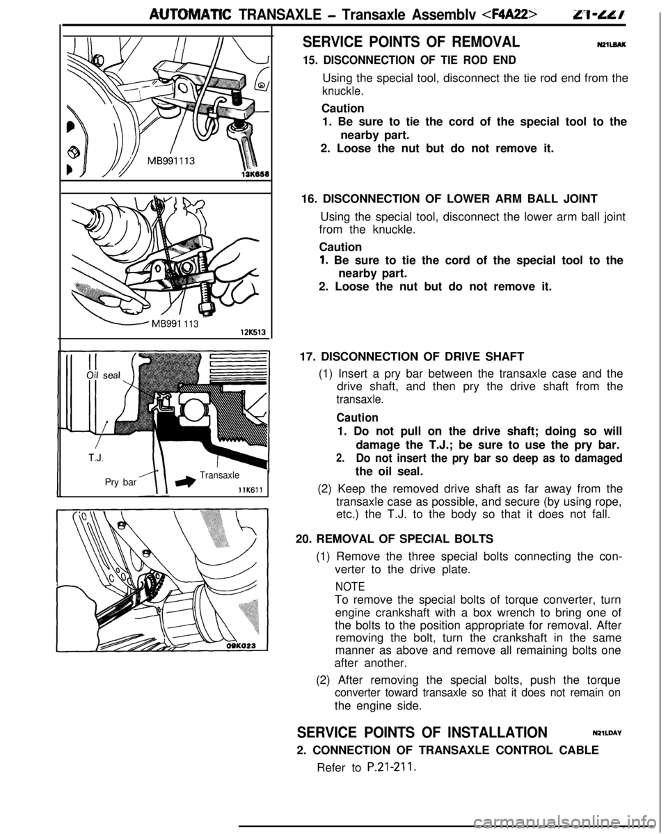
SERVICE POINTS OF REMOVALN2llEAK
15. DISCONNECTION OF TIE ROD ENDUsing the special tool, disconnect the tie rod end from the
knuckle.Caution
1. Be sure to tie the cord of the special tool to the
nearby part.
2. Loose the nut but do not remove it.
16. DISCONNECTION OF LOWER ARM BALL JOINT
Using the special tool, disconnect the lower arm ball joint
from the knuckle.
Caution
1. Be sure to tie the cord of the special tool to the
nearby part.
2. Loose the nut but do not remove it.
17. DISCONNECTION OF DRIVE SHAFT
(1) Insert a pry bar between the transaxle case and the
drive shaft, and then pry the drive shaft from the
transaxle.
Caution1. Do not pull on the drive shaft; doing so will
damage the T.J.; be sure to use the pry bar.
2.Do not insert the pry bar so deep as to damagedthe oil seal.
(2) Keep the removed drive shaft as far away from the
transaxle case as possible, and secure (by using rope,
etc.) the T.J. to the body so that it does not fall.
20. REMOVAL OF SPECIAL BOLTS
(1) Remove the three special bolts connecting the con-
verter to the drive plate.
NOTETo remove the special bolts of torque converter, turn
engine crankshaft with a box wrench to bring one of
the bolts to the position appropriate for removal. After
removing the bolt, turn the crankshaft in the same
manner as above and remove all remaining bolts one
after another.
(2) After removing the special bolts, push the torque
converter toward transaxle so that it does not remain onthe engine side.
SERVICE POINTS OF INSTALLATIONN2lWAY
2. CONNECTION OF TRANSAXLE CONTROL CABLE
Refer to
P.21-211.
Page 922 of 1216
21-228AUTOMATIC TRANSAXLE - Transaxle Assembly
DISASSEMBLY AND REASSEMBLY NZlLEBB
\18
1720
\231. Torque converter
2. Converter housing
3. Gasket
4. Oil
pump5. O-ring
6. Gasket
7. Thrust washer
#l
8.Front clutch assembly9. Thrust race #3
10. Thrust bearing #411.Thrust washer #212.Rear clutch assembly13.Spacer14.Differential
15.Thrust bearing #616.Clutch hub
17. Thrust race #7
18. Thrust bearing #819.Kickdown band20.Kickdown drum21.Snap ring
22.Center support23.O-ring
24.Wave spring25.Return spring26.Pressure plate27.Brake disc
28.Brake plate29.Reaction plate
30. Reverse sun gear31. Thrust bearing #932.Thrust race # 10
33. Forward sun gear
34.Planetary carrier35.Thrust bearing #12