Page 861 of 1216

AUTOMATIC TRANSAXLE - SeecificdionsItems
Inhibitor switch
Sprag rod support bolt
Pump housing-to-reaction shaft support
bolt
Oil assembly mounting bolt
pumpValve body bolt
Valve body assembly mounting bolt
Oil filter bolt
Speedometer sleeve locking plate bolt
End clutch cover
Kickdown lock nut
< F4A33.W4A33 >Air exhaust plug
Center bearing retainer stopper bolt
Center differential drive gear bolt
Differential cover bolt
Differential drive bolt
gearDifferential front bearing bolt
capDifferential rear bearing retainer bolt
End clutch cover bolt
Front bearing retainer bolt
Idler cover bolt
gearIdler shaft lock bolt
Inhibitor switch bolt
Kickdown servo lock nut
Manual control lever nut
Manual control shaft set screw
Oil drain bolt
Oil filter bolt
Oil level guide bolt
gaugeOil bolt
panOil check plug
pressureOil assembly mounting bolt
pumpOil pump bolt
Output bearing retainer bolt
Output flange bearing retainer bolt
Nm
IO-12
20-27
10-1215-22
4-6
10-125-7
3-5
6-8
25-32
30-354-6
70-80
10-12
130-140
60-80
30-40
10-1243-55
10-1231-44
IO-1225-32
17-21
8-10
30-355-7
20-27
10-124-6
19-23
10-12
20-2717-22
,I
‘ft.lbs.
7-915-19
,,
7-911-15
3-4
7-94-5
2-4
5-6
18-23
22-25
3-4
51-57
7-9
94-10143-58
22-29
7-9
32-39
7-922-32
7-9
18-23
12-15
6-7
-_22-25
4-5
15-19
7-93-4
13-17
7-9
15-19
12-16"/Parking rod support bolt
20-2715-19Pulse generator bolt
IO-127-9Roll stopper bracket bolt
43-55
32-39
'Shift control cable bracket bolt
20-2715-19Speedometer gear locking plate bolt
4-6
3-4
Transaxle mount bracket bolt
60-80$-,58Valve body assembly mounting bolt
10-127-9
Valve body bolt
4-6
3-4
-.
Page 862 of 1216

21-168AUTOMATIC TRANSAXLE - Specifications
-TRANSFER
ItemsNmCover mounting bolt
4-6
Driven bevel gear lock nut
140-160Extension housing mounting bolt
15-22Oil drain plug
30-35Oil filler plug
30-35Transfer case adapter mounting bolt
35-42
Transfer cover mounting bolt
35-42ft.lbs.
‘3-4
.
162-115 ‘i
‘11-1522-25
22-25
26-30
36-30
LUBRICANTSW1CD-C
ItemsSpecified lubricantQuantity
Transaxle fluidliters
(qts.) MOPAR ATF PLUS (Automatic transmission 6.1 (6.4) fluid type 7176) or Dia ATF SP7.6 (8.0)
or equivalent
:‘,Key interlock cableMOPAR Multi-mileage Lubricant PartAs required
Select lever assemblyNo. 2525035 or equivalent
Bushing, sleeve, spring,
pushbutton and lock cam
Drive shaft oil seal lipMOPAR ATF PLUS (Automatic transmission As required
fluid type 7176) or Dia ATF SP
or equivalent
SEALANTS AND ADHESIVESN2lcE-c
ItemsTransaxle case gasket
Bearing retainer screw boltsSpecified sealants and adhesives
Silicone grease
MOPAR Part
No.4318031 or MOPAR Part
No. 4318032 or equivalent
ItemsTransfer extension housing-Transfer adapter
Front bearing retainer bolts
Center differential flange bolts
Air breatherSpecified sealants and adhesives
MITSUBISHI Genuine Part
No.997740 or
equivalent::t;p,
MOPAR Part
No.4318031. or MOPAR ‘Part”’ ‘~’ “,“iNo.4318032 or equivalent’ ‘. :“’MOPAR Part No.4318025 or equivalent
Page 864 of 1216
21-170AUTOMATIC TRANSAXLE - Special Tools
Installation of bearing‘.
Removal of oil pump
MD998337
Spring compressor
Use theMD998907 andMD998338
Page 865 of 1216
AUTOMATIC TRANSAXLE - SDecial Tools21~171
MD998341Kickdown servo toolRemoval and installation of kickdown servoWrench adapter
“6”Removal and installation of transfer idler shaft
Installation of transfer shaft rear bearing and
M D998367Snap ring installerAssembly of the end clutch
eanng remover
Installation of drive shaft oil seal (W4A33)
Wrench adapterMeasurement of transfer driven bevel geardrive torque (W4A33)
Page 869 of 1216

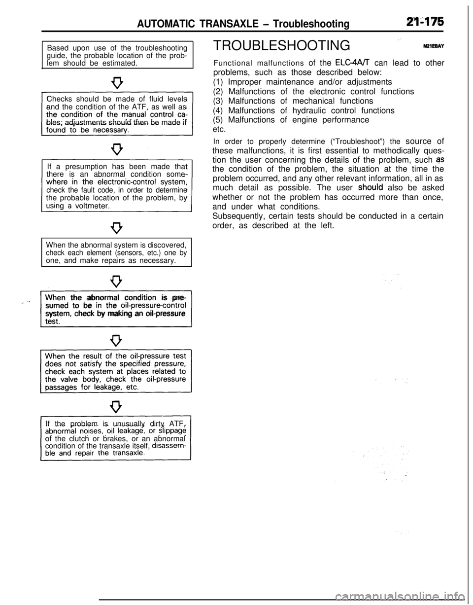
AUTOMATIC TRANSAXLE - TroubleshootingBased upon use of the troubleshooting
guide, the probable location of the prob-
lem should be estimated.
Checks should be made of fluid levels
and the condition of the ATF, as well as
bles; adjustments should then be made if
If a presumption has been made that
there is an abnormal condition some-
check the fault code, in order to determinethe probable location of the problem, by
When the abnormal system is discovered,
check each element (sensors, etc.) one byone, and make repairs as necessary.
“~^II_When the abnormal condition is pre-
sumed to be in the
orI-pressure-controlsystem, check by making an oil-pressure
If the problem is unusually dirty ATF,
of the clutch or brakes, or an abnormal
condition of the transaxle itself,
disassem-TROUBLESHOOTING
”N21EeAYFunctional malfunctions of the ELC4A/T can lead to other
problems, such as those described below:
(1) Improper maintenance and/or adjustments
(2) Malfunctions of the electronic control functions
(3) Malfunctions of mechanical functions
(4) Malfunctions of hydraulic control functions
(5) Malfunctions of engine performance
etc.In order to properly determine (“Troubleshoot”) the source of
these malfunctions, it is first essential to methodically ques-
tion the user concerning the details of the problem, such qs
the condition of the problem, the situation at the time the
problem occurred, and any other relevant information, all in as
much detail as possible. The user
shoutd also be asked
whether or not the problem has occurred more than once,
and under what conditions.
Subsequently, certain tests should be conducted in a certain
order, as described at the left.
Page 874 of 1216

21480AUTOMATIC TRANSAXLE - Troubleshootina
FAULT CODE DESCRIPTION
Code
No.Output patternDescription
Remedy
11Abnormal increase of TPS outputl Check the throttle position sensor
nconnector.
l Check the throttle position sensoritself.
12l Adjust the throttle position sensor.
Abnormal decrease of TPS outputl Check the accelerator switch
(Code No. 24output
or not).Malfunction of the throttle-
position sensor or incorrect
adjustment
Damaged or disconnected wiringl Check the oil temperature sensorof low oil temperature sensor
connector.
l Check the oil temperature sensoritself.
16Short circuit of high oil tempera-ture sensor
Damaged or disconnected wiring
of high oil temperature sensor orshort-circuit of low oil tempera-
ture sensor
21
n
Damaged or disconnected wiringl Check the kickdown servo switchof the kickdown servo switch
connector.l Check the kickdown servo switch
itself.
22
nnShort circuit of the kickdown
ser-vo switch
23Damaged or disconnected wiringl Check the ignition pulse signal line.
of the ignition pulse pick-up cable24
Short circuit of the acceleratorswitch or improper adjustmentl Check the accelerator switch con-
nectar.l Check the accelerator switch itself.
l Adjust the accelerator switch.
31
u’u I n
Damaged or disconnected wiring
of the pulse generator AlCheck the pulse generator A and
pulse generator B themselves.l Check the vehicle speed reed
switch (for chattering).32
Damaged or disconnected wiring
uuLnJ-l-of the pulse generator B
12A0104
12A0107
Page 877 of 1216

AUTOMATIC TRANSAXLE - Troubleshooting214%3
TRANSAXLE CONTROL UNIT
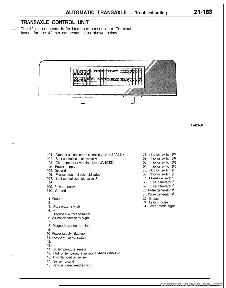
-‘” .The 42 pin connector is for increased sensor input. Terminal
layout for the 42 pin connector is as shown below.TFA0360
101.Damper clutch control solenoid valve
102.Shift control solenoid valve A
103.Oil temperature warning light 104. Power supply
105. Ground
106.Pressure control solenoid valve
107.Shift control solenoid valve B108.
-
109. Power supply
110. Ground
1. GroundL.
-
3.Accelerator switch
4.-5. Diagnosis output terminal
6. Air conditioner relay signal
7.-8. Diagnosis control terminal
9.-
IO. Power supply (Backup)
11. Kickdown servo switch
12.-
13.-14. Oil temperature sensor
15.High oil temperature sensor
16. Throttle position sensor
17.Sensor ground18. Vehicle speed reed switch
51. Inhibitor switch (PI52. Inhibitor switch
(8)53. Inhibitor switch
(N)54. Inhibitor switch
(D)
55. Inhibitor switch (2)56. inhibitor switch
(L)
57.Overdrive switch
58. Pulse generator
B59. Pulse generator
B60. Pulse generator A
61. Pulse generator A
62.Ground63.Ignition pulse64. Power mode signal
Page 882 of 1216

21-188AUTOMATIC TRANSAXLE - Troubleshooting
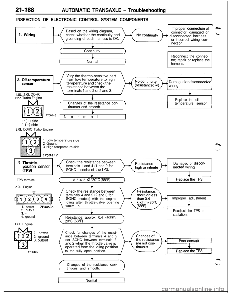
INSPECTION OF ELECTRONIC CONTROL SYSTEM COMPONENTS
Based on the wiring diagram,check whether the continuity and
grounding of each harness is OK.
+
cContinuitvJ.
4
/
.NormalI
1
Improper connection of
connector, damaged or
+ disconnected harness,or incorrect wiring con-
nection.
L
J1
Reconnect the connec-
tor; repair or replace the
harness.
I\
Vary the thermo-sensitive part
uarriageu ur ursconnecreawiring
I/
IReplace the oil-Chanaes of the resistance con-\temoerature sensortinuo& and smooth.4
I 1750446 -Normal,
1: (+) side2:
(-) side
2.0L DOHC TurboEngine
1I
Y3.
Throttle-Check the resistance betweenosition sensorterminals 1 and 4 (1 and 2 forDamaged or discon-
PTPS)SOHC models) of theTPS.netted wiringI
I
TPS termrnal
2.0L Engine
1. power
7FUO5352. output3. -4. ground
1.8L Engine
1. power
2. ground
3. output
+
(3.5-6.5 S2/2O”C (68°F)1Check the resistance between
terminals 4 and 2 (2 and 3 forSOHC models) with the engine
idling after throttle-valve opening
warm-up.
4
Resistance: approx. 0.4 kilohml
20°C (68°F)I
Improper adjustment
J
’Readjust the TPS in-
stallation.Check for changes of the resist-
ance between terminals 4 and 2
(for SOHC between terminals 3
and 2 when the throttle valve is
operated from the idling position
to the fully open position.
4Changes of the resistance con-
tinuous and smooth.
4
Normal