Page 327 of 1216
ENGINE <1.8L Engine> - Timing Belt9-43
-
.
4iJ
:
,000008
7EN206
Crack
7EN207Abnormal wear
(fluffy canvas fiber)7EN2013
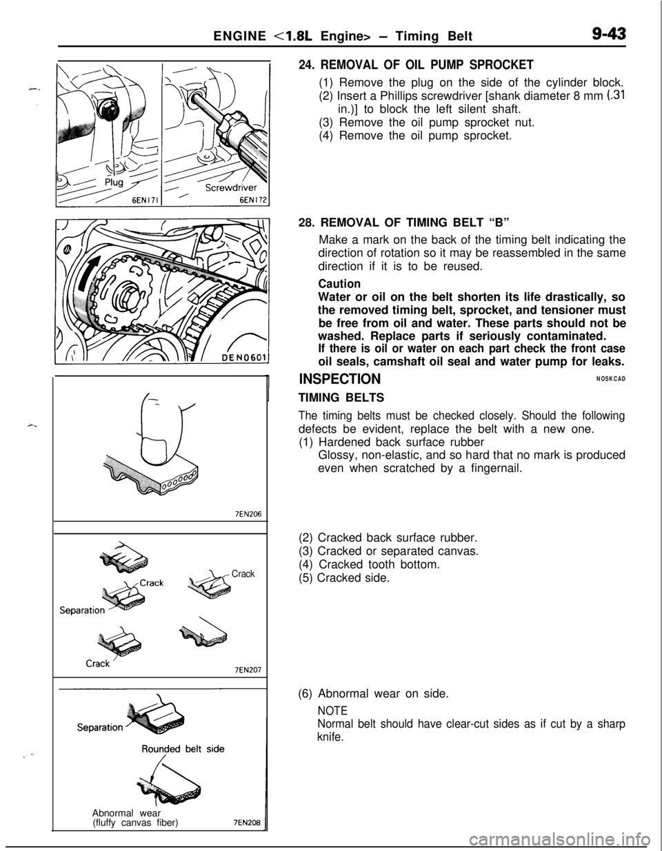
24. REMOVAL OF OIL PUMP SPROCKET(1) Remove the plug on the side of the cylinder block.
(2) Insert a Phillips screwdriver [shank diameter 8 mm
(.31in.)] to block the left silent shaft.
(3) Remove the oil pump sprocket nut.
(4) Remove the oil pump sprocket.
28. REMOVAL OF TIMING BELT “B”
Make a mark on the back of the timing belt indicating the
direction of rotation so it may be reassembled in the same
direction if it is to be reused.
CautionWater or oil on the belt shorten its life drastically, so
the removed timing belt, sprocket, and tensioner must
be free from oil and water. These parts should not be
washed. Replace parts if seriously contaminated.
If there is oil or water on each part check the front caseoil seals, camshaft oil seal and water pump for leaks.
INSPECTIONNOSKCADTIMING BELTS
The timing belts must be checked closely. Should the followingdefects be evident, replace the belt with a new one.
(1) Hardened back surface rubber
Glossy, non-elastic, and so hard that no mark is produced
even when scratched by a fingernail.
(2) Cracked back surface rubber.
(3) Cracked or separated canvas.
(4) Cracked tooth bottom.
(5) Cracked side.
(6) Abnormal wear on side.
NOTE
Normal belt should have clear-cut sides as if cut by a sharp
knife.
Page 328 of 1216
9-44ENGINE <1.8L Engine> - Timing Belt
Rubber
exposedTooth missing and
1 EN0002
Crankshaftsprocket “6
Crankshaft 6EN304
Spacer
Chamfered
6EN009
J
TiGGrnmarkCrankshaft
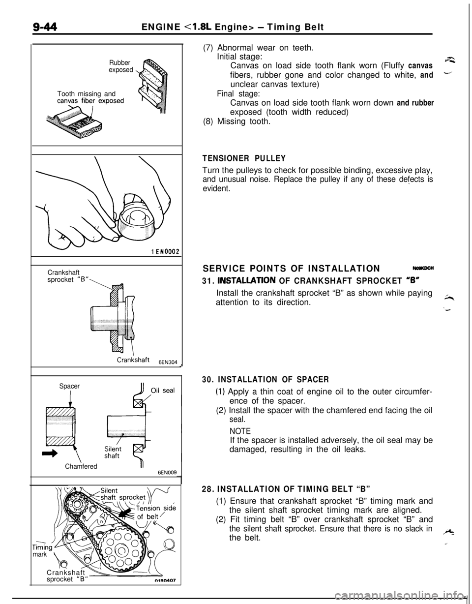
\vsprocket “B”(7) Abnormal wear on teeth.
Initial stage:
Canvas on load side tooth flank worn (Fluffy canvas
afibers, rubber gone and color changed to white, and
-unclear canvas texture)
Final stage:Canvas on load side tooth flank worn down and rubber
exposed (tooth width reduced)
(8) Missing tooth.
TENSIONER PULLEYTurn the pulleys to check for possible binding, excessive play,
and unusual noise. Replace the pulley if any of these defects is
evident.”
SERVICE POINTS OF INSTALLATION
31. INSTALLATlON OF CRANKSHAFT SPROCKET “6”Install the crankshaft sprocket “B” as shown while paying
attention to its direction.
~,
‘d
30. INSTALLATION OF SPACER
(1) Apply a thin coat of engine oil to the outer circumfer-
ence of the spacer.
(2) Install the spacer with the chamfered end facing the oil
seal.
NOTEIf the spacer is installed adversely, the oil seal may be
damaged, resulting in the oil leaks.
28. INSTALLATION OF TIMING BELT “B”(1) Ensure that crankshaft sprocket “B” timing mark and
the silent shaft sprocket timing mark are aligned.
(2) Fit timing belt “B” over crankshaft sprocket “B” and
the silent shaft sprocket. Ensure that there is no slack inthe belt.+
a.
Page 329 of 1216

ENGINE <1.8L Engine> - Timing Belt9-45
J
I01R0409
Crankshaftsprocket )IB”
I
CrankshafisprocketCrankshaft
6EN2721
. ADJUSTMENT OF TIMING BELT “B” TENSION(1) Temporarily fix the timing belt “B” tensioner such that
the center of the tensioner pulley is to the left and
above the center of the installation bolt, and temporarilyattach the tensioner pulley so that the flange is toward
the front of the engine.
(2) Holding the timing belt“B” tensioner up with your
finger in the direction of the arrow, place pressure on
the timing belt so that the tension side of the belt is
taut. Now tighten the bolt to fix the tensioner.
Caution
When tightening the bolt, ensure that the tensioner
pulley shaft does not rotate with the bolt. Allowing
it to rotate with the bolt can cause excessive
tension on the belt.(3) To ensure that the tension is correct, depress the belt
(point A) with a finger. If not, adjust.
Standard value: 5-7 mm (.20-.28 in.)
26. INSTALLATION OF FLANGEInstall the flange in correct direction as shown.
22. INSTALLATION OF TENSIONER SPRING/21. TEN-
SIONER SPACERI20. TIMING BELT TENSIONER
(1) Install the tensioner spring, tensioner spacer and timingbelt tensioner.
(2) Place the upper end of the tensioner spring against the
water pump body.
Page 330 of 1216
9-46ENGINE <1.8L Engine> - Timing Belt
Timing mark
Q1hQS4.9
3EN005
OlA0549
c
::
OlAO550-(3) Move tensioner fully toward water pump and tempor-
arily secure tensioner.
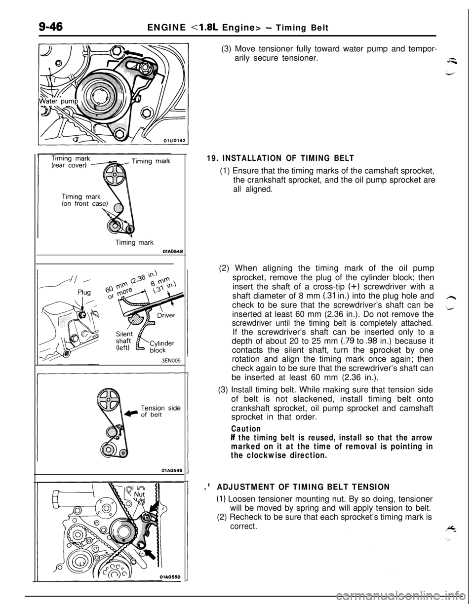
19. INSTALLATION OF TIMING BELT(1) Ensure that the timing marks of the camshaft sprocket,
the crankshaft sprocket, and the oil pump sprocket are
all aligned.(2) When aligning the timing mark of the oil pump
sprocket, remove the plug of the cylinder block; then
insert the shaft of a cross-tip (+) screwdriver with a
shaft diameter of 8 mm
(.31 in.) into the plug hole and
check to be sure that the screwdriver’s shaft can be
inserted at least 60 mm (2.36 in.). Do not remove the
screwdriver until the timing belt is completely attached.If the screwdriver’s shaft can be inserted only to a
depth of about 20 to 25 mm
(.79 to .98 in.) because it
contacts the silent shaft, turn the sprocket by one
rotation and align the timing mark once again; then
check again to be sure that the screwdriver’s shaft can
be inserted at least 60 mm (2.36 in.).
(3) Install timing belt. While making sure that tension side
of belt is not slackened, install timing belt onto
crankshaft sprocket, oil pump sprocket and camshaft
sprocket in that order.
Caution
If the timing belt is reused, install so that the arrow
marked on it at the time of removal is pointing in
the clockwise direction..
ADJUSTMENT OF TIMING BELT TENSION
(1) Loosen tensioner mounting nut. By so doing, tensioner
will be moved by spring and will apply tension to belt.
(2) Recheck to be sure that each sprocket’s timing mark is
correct.
Page 331 of 1216
ENGINE <1.8L Engine> - Timing Belt9-47
Timing mark
Nut
;olt diameter x lengthim (in.)
6x50(.23 x 1.97)
6
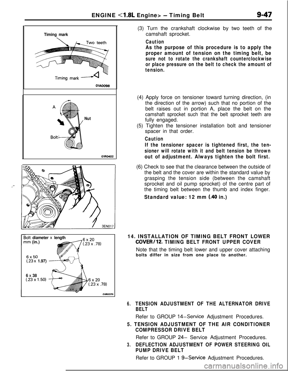
x 38(.23 x 1.50)(3) Turn the crankshaft clockwise by two teeth of the
camshaft sprocket.
Caution
As the purpose of this procedure is to apply the
proper amount of tension on the timing belt, be
sure not to rotate the crankshaft counterclockwise
or place pressure on the belt to check the amount of
tension.(4) Apply force on tensioner toward turning direction, (in
the direction of the arrow) such that no portion of the
belt raises out in portion A, place the belt on the
camshaft sprocket such that the belt sprocket teeth arefully engaged.
(5) Tighten the tensioner installation bolt and tensioner
spacer in that order.
Caution
If the tensioner spacer is tightened first, the ten-
sioner will rotate with it and belt tension be thrown
out of adjustment. Always tighten the bolt first.(6) Check to see that the clearance between the outside of
the belt and the cover are within the standard value by
grasping the tension side (between the camshaft
sprocket and oil pump sprocket) of the centre part of
the timing belt between the thumb and index finger.
Standard value: 12 mm (.40 in.)
14. INSTALLATION OF TIMING BELT FRONT LOWER
COVER/12. TIMING BELT FRONT UPPER COVERNote that the timing belt lower and upper cover attaching
bolts differ in size from one place to another.
6.TENSION ADJUSTMENT OF THE ALTERNATOR DRIVE
BELTRefer to GROUP
14-Service Adjustment Procedures.
5. TENSION ADJUSTMENT OF THE AIR CONDITIONER
COMPRESSOR DRIVE BELTRefer to GROUP
24- Service Adjustment Procedures.
3.DEFLECTION ADJUSTMENT OF POWER STEERING OIL
PUMP DRIVE BELTRefer to GROUP 1
g-Service Adjustment Procedures.
Page 338 of 1216
ENGINE - Cylinder Head and ValveSERVICE POINTS OF DISASSEMBLY
1. REMOVAL OF CYLINDER HEAD BOLTS
3EN123Front of engine (Timing belt side)
c
1 EN025
3EN324Loosen the bolts in the order shown.
Loosen them little by little and uniformly.
5./9. REMOVAL OF RETAINER LOCKS(1) Using the special
tool, remove the retainer locks.
(2) Keep the removed retainer locks valve by valve so that
they can be reinstalled in their original positions.
A
13.115. REMOVAL OF VALVE STEM SEALRemove the stem seals with pliers. Do not reuse the valve
stem seal.
Page 347 of 1216
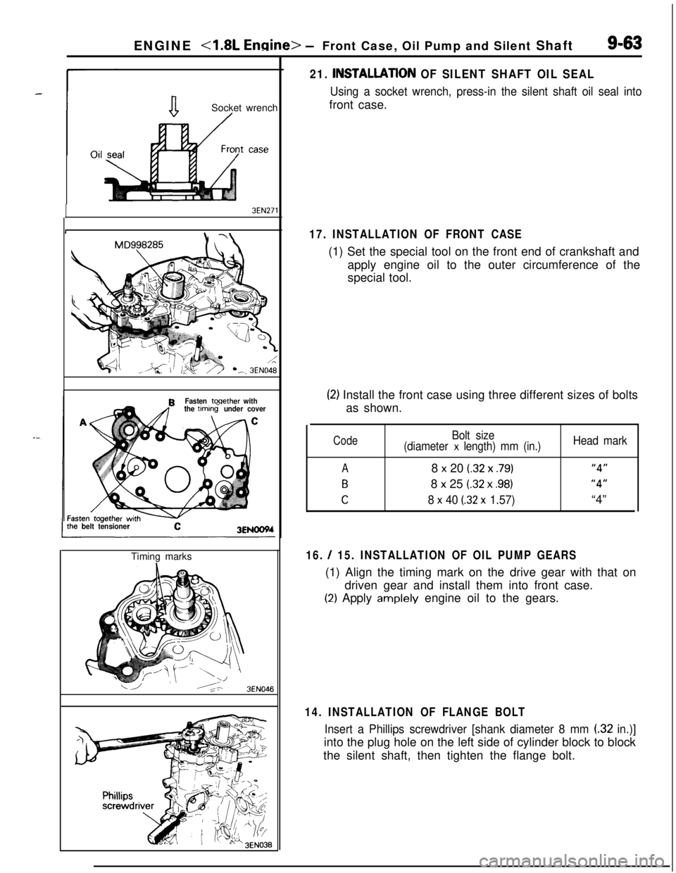
ENGINE <1.8L Engine> -Front Case, Oil Pump and Silent Shaft9-63
aSocket wrench/
3EN271
MD998285R
Fasten toqether with
the timtins under cover
C
belt tensioner3ENOOWTiming marks
16. / 15. INSTALLATION OF OIL PUMP GEARS(1) Align the timing mark on the drive gear with that on
driven gear and install them into front case.
(2) Apply amplely engine oil to the gears.
3EN046
21. INSTALLATlON OF SILENT SHAFT OIL SEAL
Using a socket wrench, press-in the silent shaft oil seal intofront case.
17. INSTALLATION OF FRONT CASE(1) Set the special tool on the front end of crankshaft and
apply engine oil to the outer circumference of the
special tool.
(2) Install the front case using three different sizes of bolts
as shown.
Code
A
B
C
Bolt size
(diameter x length) mm (in.)8
x 20 (.32 x .79)8
x 25 (.32 x .98)
8 x 40 (32 x 1.57)
Head mark
“4”
“4”“4”
14. INSTALLATION OF FLANGE BOLT
Insert a Phillips screwdriver [shank diameter 8 mm (32 in.)]into the plug hole on the left side of cylinder block to block
the silent shaft, then tighten the flange bolt.
Page 352 of 1216
9-68ENGINE <1.8L Engine> - Piston and Connecting Rod
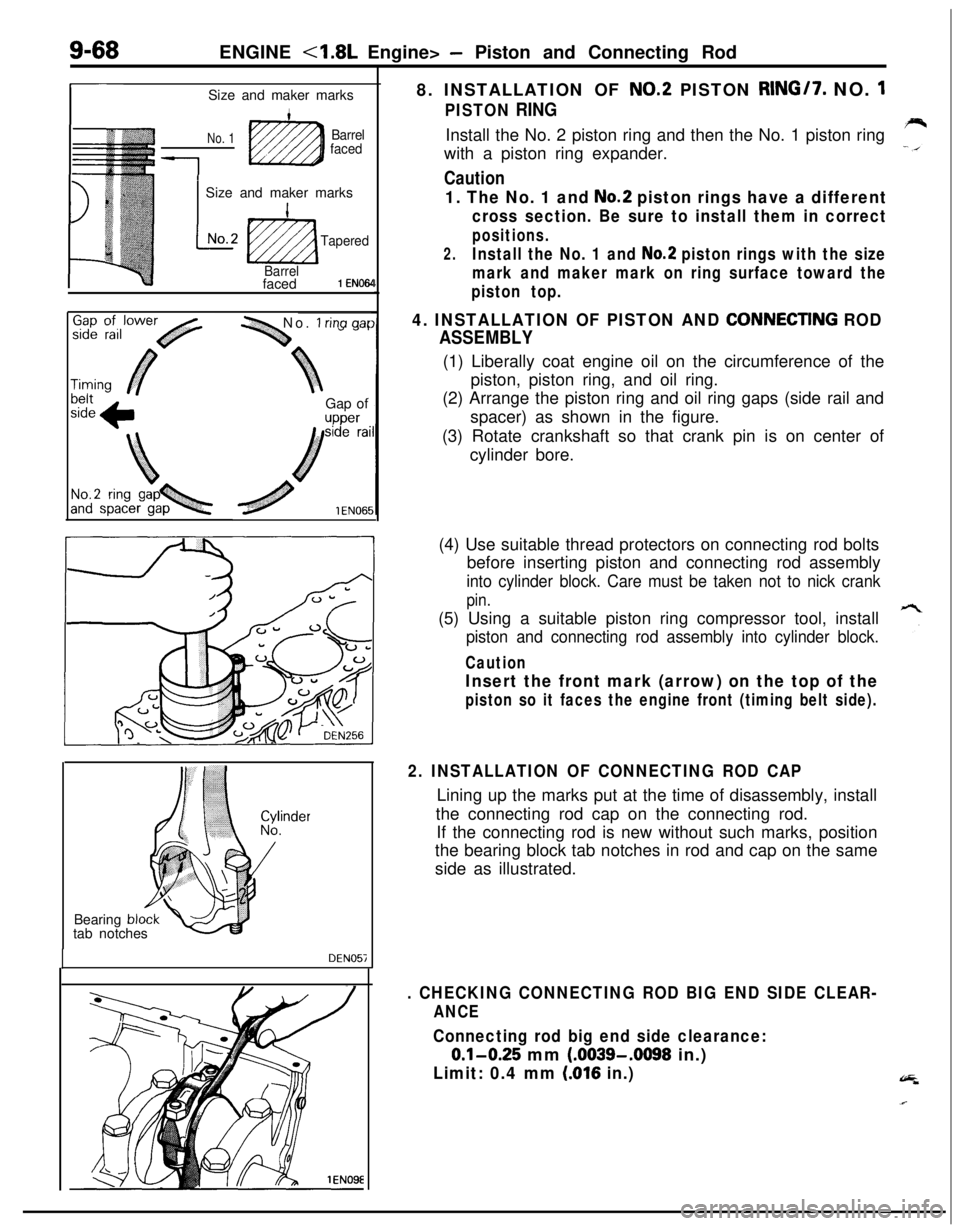
r-Size and maker marks
No. 1Barrel
faced
1
1 Size and maker marks
L
INo.2
ti2zza
Tapered
Barrelfaced
1 EN064
-1 No. 1 rina aarGap of
upper8. INSTALLATION OF
NO.2 PISTON RING/7. NO. 1
PISTON RINGInstall the No. 2 piston ring and then the No. 1 piston ring
with a piston ring expander.
Caution
1. The No. 1 and No.2 piston rings have a different
cross section. Be sure to install them in correct
positions.
2.Install the No. 1 and No.2 piston rings with the size
mark and maker mark on ring surface toward the
piston top.
4. INSTALLATION OF PISTON AND CONNECTlNG ROD
ASSEMBLY(1) Liberally coat engine oil on the circumference of the
piston, piston ring, and oil ring.
(2) Arrange the piston ring and oil ring gaps (side rail and
spacer) as shown in the figure.
(3) Rotate crankshaft so that crank pin is on center of
cylinder bore.
Bearing
bltab notches
DEN057(4) Use suitable thread protectors on connecting rod bolts
before inserting piston and connecting rod assembly
into cylinder block. Care must be taken not to nick crank
pin.(5) Using a suitable piston ring compressor tool, install
piston and connecting rod assembly into cylinder block.
Caution
Insert the front mark (arrow) on the top of the
piston so it faces the engine front (timing belt side).
2. INSTALLATION OF CONNECTING ROD CAPLining up the marks put at the time of disassembly, install
the connecting rod cap on the connecting rod.
If the connecting rod is new without such marks, position
the bearing block tab notches in rod and cap on the same
side as illustrated.
. CHECKING CONNECTING ROD BIG END SIDE CLEAR-
ANCE
Connecting rod big end side clearance:
0.1-0.25 mm (.0039-.0098 in.)
Limit: 0.4 mm (016 in.)