Page 276 of 1216
7-28COOLING- Water Hose and Water Pipe <2.0L DOHC Engine (Non-Turbo)>
<2.0L DOHC Engine (Non-Turbo)>
REMOVAL AND INSTALLATION
Post-installgtion Pperation@Supplying of the Engine Coolant(FF$efeet; GROUP O-Maintenance
6
/5
/l--5ia
225-30 Nm
18-22
ft.lbs.
12-1s Nrn9-11 ft.lbs.
Removal steps1 Air intake hose
2. Condenser fan motor assembly
3. Self-locking nut4. Gasket
5. Oxygen sensor harness connector
6. Exhaust manifold cover (A)7. Self-locking nut
8. Engine hanger
04A01059. Exhaust manifold
10. Exhaust manifold gasket11. Exhaust manifold cover(B)
NOTE(1) Reverse the removal procedures to reinstall.(21 m : Non-reusable parts
Page 279 of 1216
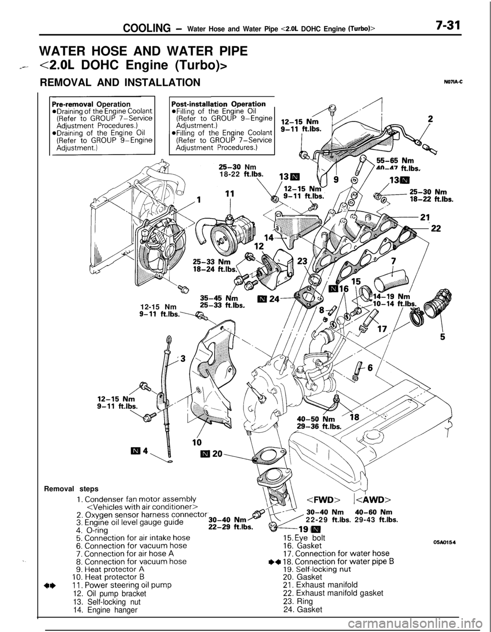
COOLING -Water Hose and Water Pipe <2.0L DOHC Engine (Turbo)>7-31WATER HOSE AND WATER PIPE
7--<2.0L DOHC Engine (Turbo)>
REMOVAL AND INSTALLATION
N071A-C
. .
ation OperationPost-installi@Filling of the Engine Oil(Refer to GROUP g-EngineaFilling of the
Engine Coolant(Refer to GROUP 7-ServiceAdjustment Procedures.)
Pre-removal OperationeDraining of the Engine Coolant(Refer to GROUP 7-ServiceAdjustment Procedures.)*Draining of the Engine Oil(Refer to GROUP g-Engine
25-30 Nm
18-22 ftlbs.4n-47 ft.lbs.
w35-45 N/m12-15 Nm25-33 ft.lbs.
9- 11ft.lbs.----Q&Removal steps
1. Condenser fan motor assembly2. Oxygen sensor harness connector3. Engine oil level gauge guide4. O-ring5. Connection for air intake hose6. Connection for vacuum hose7. Connection for air hose A8. Connection for vacuum hose9. Heat protector A10. Heat protector B
4*11. Power steering oil pump
12. Oil pump bracket
13. Self-locking nut
14. Engine hanger22-29
ft.lbs. 29-43 ft.lbs.
15. Eye bolt16. Gasket17. Connection for water hose
I)+ 18. Connection for water pipe B19. Self-locking nut20. Gasket21. Exhaust manifold22. Exhaust manifold gasket
23. Ring
24. Gasket
05m154
Page 282 of 1216
7-34 COOLINGWater Hose and Water Pipe <2.0L DOHC Engine (Turbo)>/Engine Coolant Temperature- Gauge Unit. Engine Coolant Temoerature Sensor and Enoine Coolant Temoerature Switch
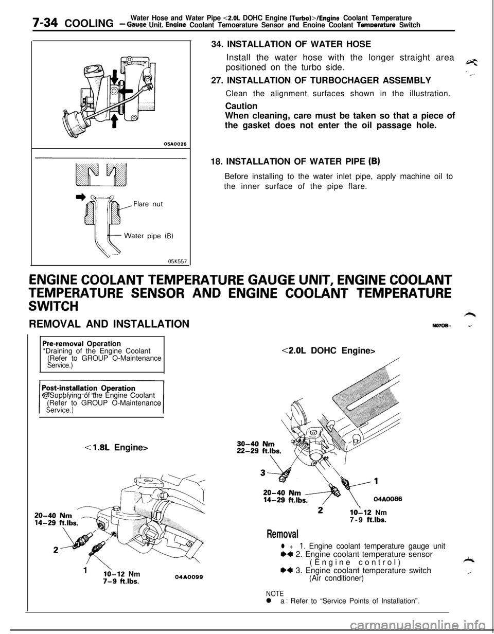
05A0026
05K55734. INSTALLATION OF WATER HOSE
Install the water hose with the longer straight area
positioned on the turbo side.
27. INSTALLATION OF TURBOCHAGER ASSEMBLY
Clean the alignment surfaces shown in the illustration.
Caution
When cleaning, care must be taken so that a piece of
the gasket does not enter the oil passage hole.
18. INSTALLATION OF WATER PIPE
(B)Before installing to the water inlet pipe, apply machine oil to
the inner surface of the pipe flare.
ENGINE COOLANT TEMPERATURE GAUGE UNIT, ENGINE COOLANT
TEMPERATURE SENSOR AND ENGINE COOLANT TEMPERATURE
SWITCHREMOVAL AND INSTALLATION
N070%-
Pre-removal Operation
*Draining of the Engine Coolant
(Refer to GROUP O-Maintenance
Service.)@Supplying of the Engine Coolant
(Refer to GROUP O-Maintenance
< 1.8L Engine>
20-4014-291
’lo-12 Nm7-9 ft.lbs.04AOO99<2.0L DOHC Engine>10112 Nm
7-9 ft.lbs.
Removal
l +1. Engine coolant temperature gauge unit
++ 2. Engine coolant temperature sensor
(Engine control)
*4 3. Engine coolant temperature switch(Air conditioner)
NOTEl a : Refer to “Service Points of Installation”.
Page 283 of 1216
COOLINGEngine Coolant Temperature Gauge Unit, Engine Coolant- TemDerature Sensor and Enaine Coolant Temperature Switch7-35
.---
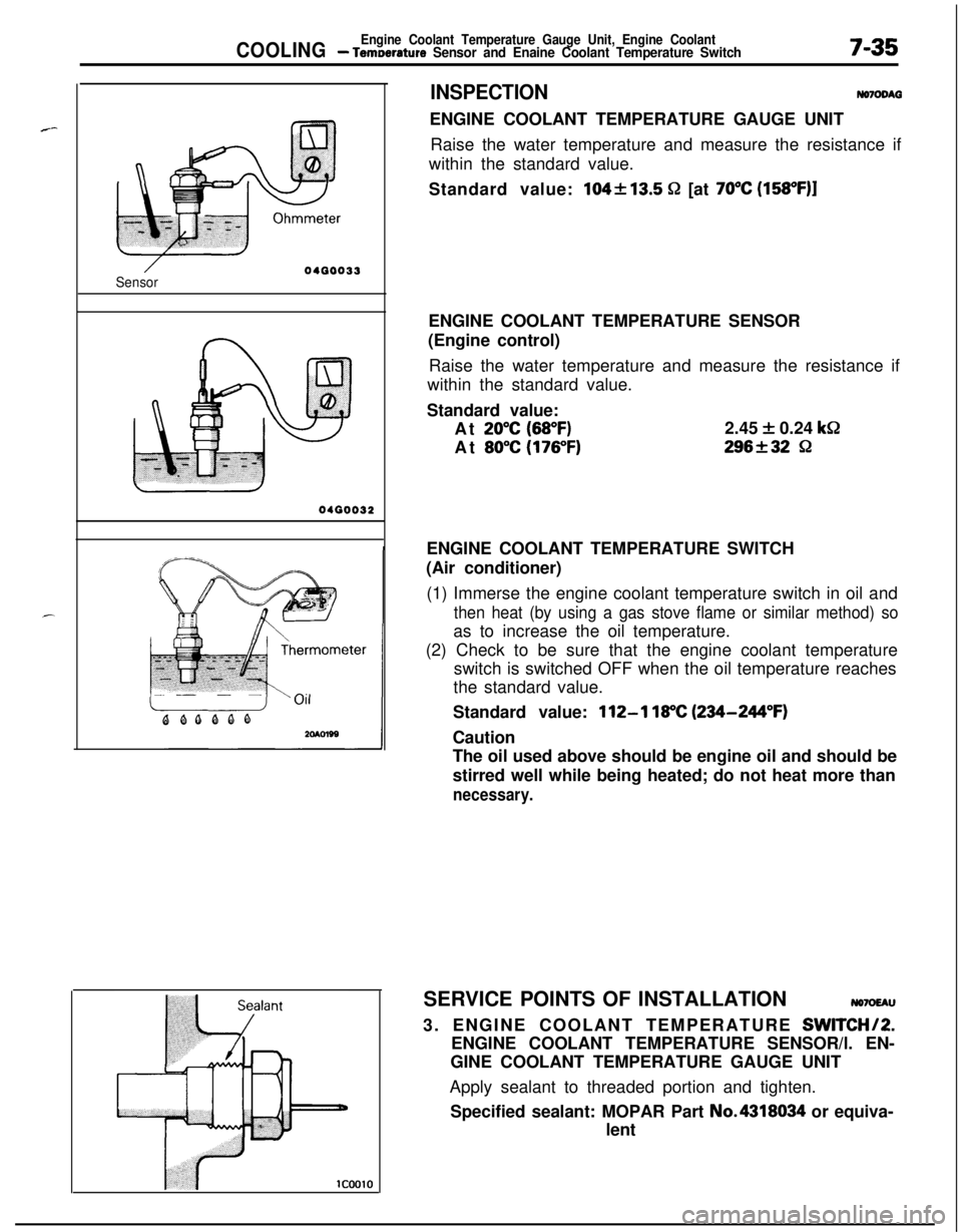
Sensor04GO033
0400032
1c0010
INSPECTIONNomDM3ENGINE COOLANT TEMPERATURE GAUGE UNIT
Raise the water temperature and measure the resistance if
within the standard value.
Standard value:
104213.5 52 [at 70°C (158OF)lENGINE COOLANT TEMPERATURE SENSOR
(Engine control)
Raise the water temperature and measure the resistance if
within the standard value.
Standard value:
At
20°C (68°F)2.45 + 0.24 k&
At
80°C (176°F)296f32 8ENGINE COOLANT TEMPERATURE SWITCH
(Air conditioner)
(1) Immerse the engine coolant temperature switch in oil and
then heat (by using a gas stove flame or similar method) soas to increase the oil temperature.
(2) Check to be sure that the engine coolant temperature
switch is switched OFF when the oil temperature reaches
the standard value.
Standard value:
112-l 18°C (234-244°F)Caution
The oil used above should be engine oil and should be
stirred well while being heated; do not heat more than
necessary.SERVICE POINTS OF INSTALLATION
NO7OEAU3. ENGINE COOLANT TEMPERATURE
SWITCHI2.ENGINE COOLANT TEMPERATURE SENSOR/l. EN-
GINE COOLANT TEMPERATURE GAUGE UNIT
Apply sealant to threaded portion and tighten.
Specified sealant: MOPAR Part No.4318034 or equiva-
lent
Page 291 of 1216
ENGINE - General Information9-7
LUBRICATION SYSTEM <2.0L DOHC Engine>Engine coolant
(from thermostat
case)a
Oil filterRoller rocker arm
LashadjusterCan
/
ILt
K
63
ishaftOil jet
(Turbo only)
Oil pump I y+Oilscreen /6LUOO52
Page 308 of 1216
9-24ENGINE - Service Adjustment Procedures
ENGINE 4.8L Engine>
SERVICE ADJUSTMENT PROCEDURES -
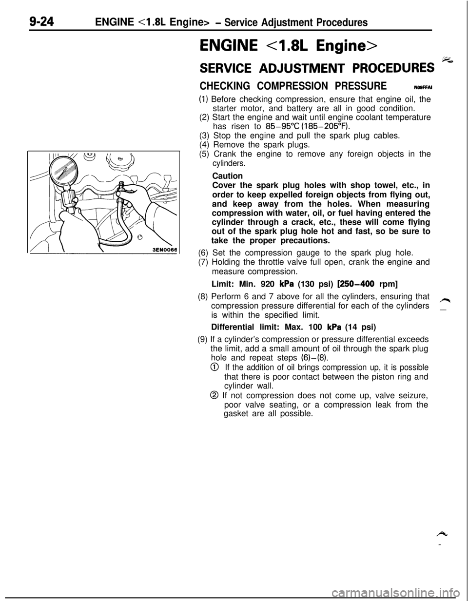
CHECKING COMPRESSION PRESSURENOSFFAI
(1) Before checking compression, ensure that engine oil, the
starter motor, and battery are all in good condition.
(2) Start the engine and wait until engine coolant temperature
has risen to
85-95°C (185-205°F).
(3) Stop the engine and pull the spark plug cables.
(4) Remove the spark plugs.
(5) Crank the engine to remove any foreign objects in the
cylinders.Caution
Cover the spark plug holes with shop towel, etc., in
order to keep expelled foreign objects from flying out,
and keep away from the holes. When measuring
compression with water, oil, or fuel having entered the
cylinder through a crack, etc., these will come flying
out of the spark plug hole hot and fast, so be sure to
take the proper precautions.
(6) Set the compression gauge to the spark plug hole.
(7) Holding the throttle valve full open, crank the engine and
measure compression.
Limit: Min. 920
kPa (130 psi) [250-400 rpm]
(8) Perform 6 and 7 above for all the cylinders, ensuring that
compression pressure differential for each of the cylinders
/Iis within the specified limit.
__Differential limit: Max. 100
kPa (14 psi)
(9) If a cylinder’s compression or pressure differential exceeds
the limit, add a small amount of oil through the spark plug
hole and repeat steps (6)-(8).
0If the addition of oil brings compression up, it is possiblethat there is poor contact between the piston ring and
cylinder wall.
@ If not compression does not come up, valve seizure,
poor valve seating, or a compression leak from the
gasket are all possible.
/y
-
Page 309 of 1216
ENGINE <1.8L Engine>- Service Adjustment Procedures9-25
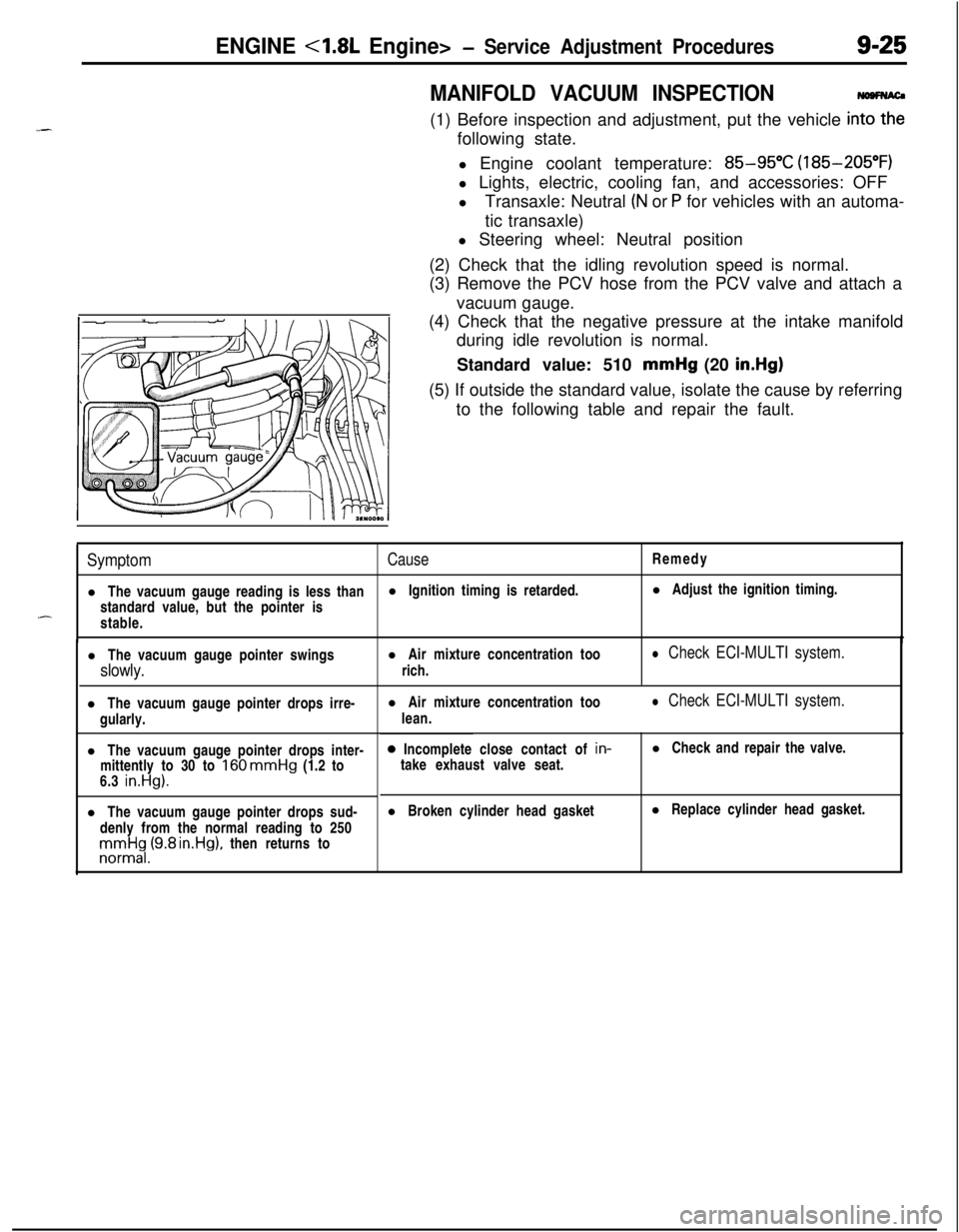
MANIFOLD VACUUM INSPECTION(1) Before inspection and adjustment, put the vehicle
in=following state.
l Engine coolant temperature:
85-95°C (185-205°F)
l Lights, electric, cooling fan, and accessories: OFF
lTransaxle: Neutral
(N or P for vehicles with an automa-
tic transaxle)
l Steering wheel: Neutral position
(2) Check that the idling revolution speed is normal.
(3) Remove the PCV hose from the PCV valve and attach a
vacuum gauge.
(4) Check that the negative pressure at the intake manifold
during idle revolution is normal.
Standard value: 510 mmHg (20
in.Hg)(5) If outside the standard value, isolate the cause by referring
to the following table and repair the fault.
SymptomCauseRemedy
l The vacuum gauge reading is less thanl Ignition timing is retarded.l Adjust the ignition timing.
standard value, but the pointer is
-stable.
l The vacuum gauge pointer swingsl Air mixture concentration too
slowly.rich.
l Check ECI-MULTI system.l The vacuum gauge pointer drops irre-
gularly.
l The vacuum gauge pointer drops inter-
mittently to 30 to
160 mmHg (1.2 to
6.3 in.Hg).l The vacuum gauge pointer drops sud-
denly from the normal reading to 250rronnrt$,(9.8 rn.Hg), then returns tol Air mixture concentration too
lean.
l Check ECI-MULTI system.0 Incomplete close contact of in-
take exhaust valve seat.l Check and repair the valve.
l Broken cylinder head gasketl Replace cylinder head gasket.
Page 315 of 1216
ENGINE <1.8L Engine> - Engine Assembly9-31
ENGINE ASSEMBLY
. REMOVAL AND INSTALLATION
N69SA-APre-removal Operation
@Eliminating Fuel Pressure in Fuel Line
(Refer to GROUP 14-Service AdjustmentProcedures.)@Removal of Engine HoodeDraining of Engine Coolant
(Refer to GROUP O-Maintenance Service.)
l Removal of the Transaxle Assembly(Refer to GROUP 21 -Transaxle Assembly.)
*Removal of the Radiator
(Refer to GROUP 7-Radiator.)
Post-installation Operation
@Installation of the Radiator
(Refer to GROUP 7-Radiator.)
l Installation of the Transaxle Assembly(Refer to GROUP 21 -Transaxle Assembly.)
@Refilling of Engine Coolant
(Refer to GROUP O-Maintenance Service.)
l Installation of Engine Hood4-6 Nm
“7
/61OlA05664-6 Nm
3-4
ft.lbs.
\
16
/io1\4-6Nm164-6Nm193-4ft.lbs.
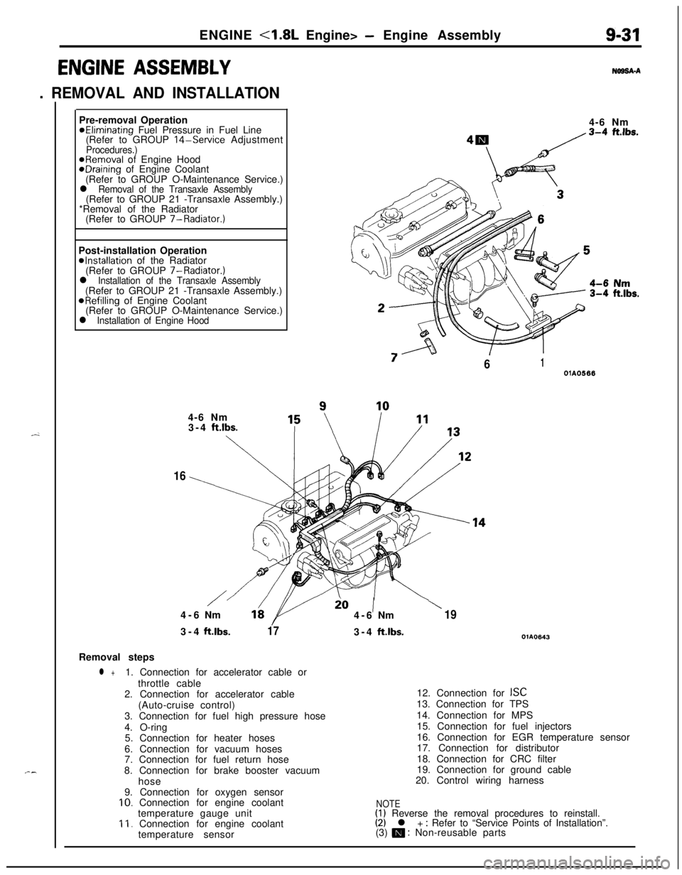
173-4ft.lbs.OlA0643Removal steps
l +1. Connection for accelerator cable or
throttle cable
2. Connection for accelerator cable
(Auto-cruise control)
3. Connection for fuel high pressure hose
4. O-ring
5. Connection for heater hoses
6. Connection for vacuum hoses
7. Connection for fuel return hose
8. Connection for brake booster vacuum
hose
9. Connection for oxygen sensor
10. Connection for engine coolant
temperature gauge unit
11. Connection for engine coolant
temperature sensor12. Connection for
ISC13. Connection for TPS
14. Connection for MPS
15. Connection for fuel injectors
16. Connection for EGR temperature sensor
17. Connection for distributor
18. Connection for CRC filter
19. Connection for ground cable
20. Control wiring harness
NOTE(1) Reverse the removal procedures to reinstall.(2) l + : Refer to “Service Points of Installation”.
(3) m : Non-reusable parts