Page 250 of 1216
7-2COOLING - Specifications
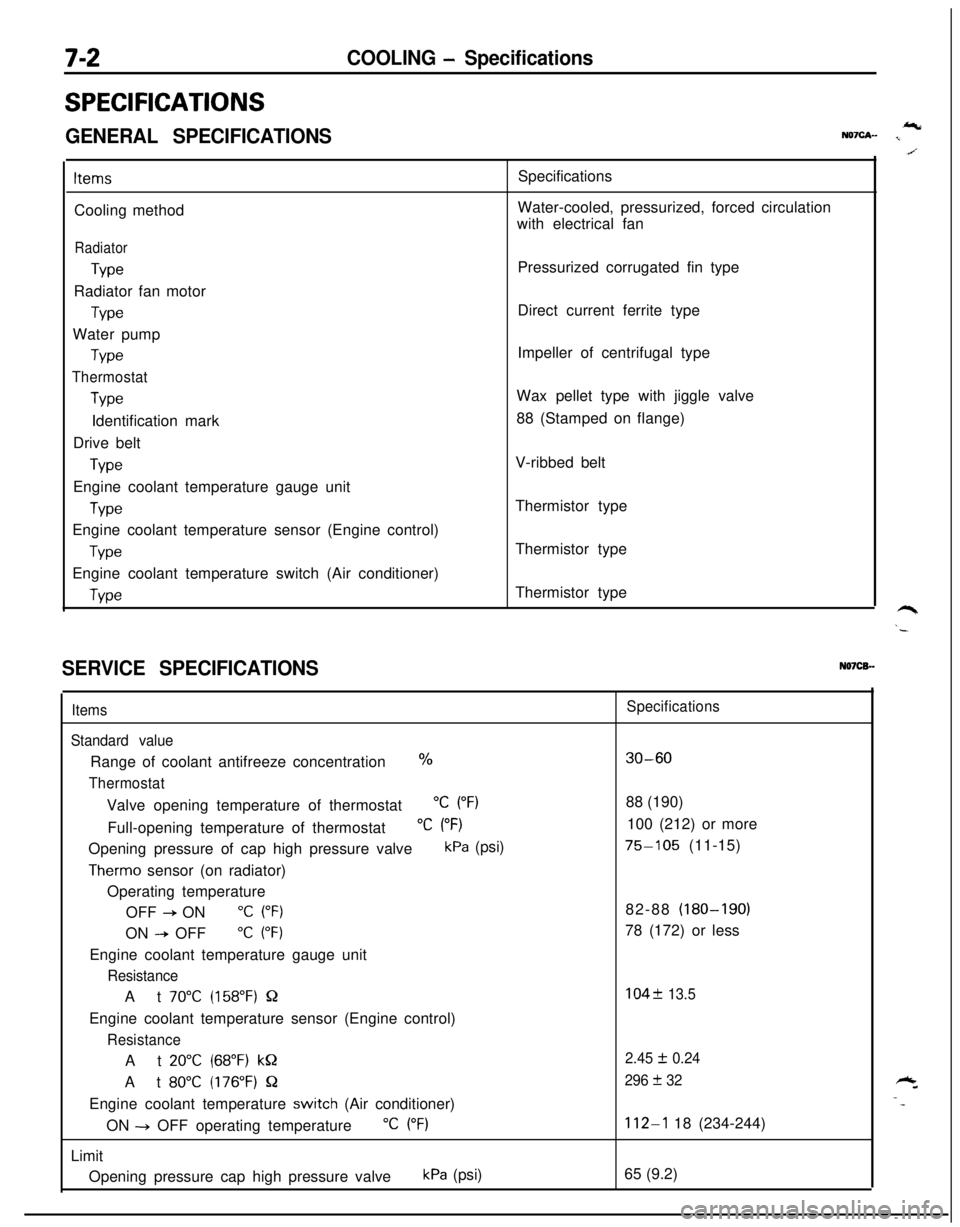
SPECIFICATIONS
GENERAL SPECIFICATIONSIcNQ7cA- I
ItemsCooling method
Radiator
TypeRadiator fan motor
TypeWater pump
Type
Thermostat
TypeIdentification mark
Drive belt
TypeEngine coolant temperature gauge unit
WeEngine coolant temperature sensor (Engine control)
TypeEngine coolant temperature switch (Air conditioner)
WeSpecifications
Water-cooled, pressurized, forced circulation
with electrical fan
Pressurized corrugated fin type
Direct current ferrite type
Impeller of centrifugal type
Wax pellet type with jiggle valve
88 (Stamped on flange)
V-ribbed belt
Thermistor type
Thermistor type
Thermistor type
SERVICE SPECIFICATIONSN07CB.-
Items
Standard valueRange of coolant antifreeze concentration
%
ThermostatValve opening temperature of thermostat
“C (“F)Full-opening temperature of thermostat
“C (“F)Opening pressure of cap high pressure valve
kPa (psi)
Therm0 sensor (on radiator)
Operating temperature
OFF
+ ON“C (“F)ON
--P OFF“C (“F)Engine coolant temperature gauge unit
ResistanceAt
70°C (158°F) QEngine coolant temperature sensor (Engine control)
ResistanceAt
20°C (68°F) kQAt
80°C (176°F) QEngine coolant temperature
switch (Air conditioner)
ON -+ OFF operating temperature
“C (“F)Limit
Opening pressure cap high pressure valve
kPa (psi)
Specifications
30-6088 (190)
100 (212) or more
75-105 (11-15)
82-88 (180-190)
78 (172) or less
104f 13.5
2.45
I!I 0.24
296
+ 32
112-l 18 (234-244)
65 (9.2)
Page 252 of 1216
7-4COOLING - Specifications
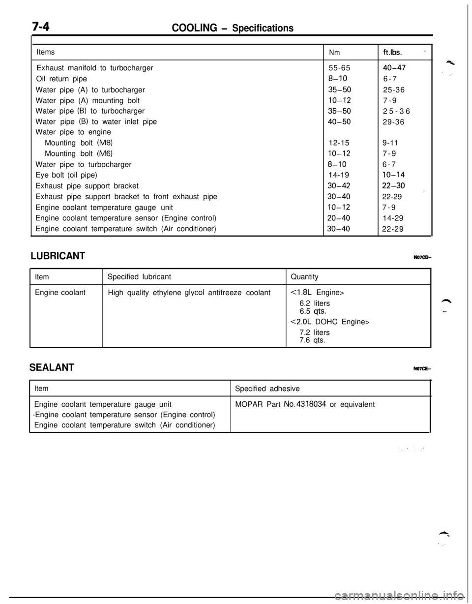
ItemsExhaust manifold to turbocharger
Oil return pipe
Water pipe (A) to turbocharger
Water pipe (A) mounting bolt
Water pipe
(B) to turbocharger
Water pipe
(B) to water inlet pipe
Water pipe to engine
Mounting bolt
(M8)Mounting bolt
(M6)Water pipe to turbocharger
Eye bolt (oil pipe)
Exhaust pipe support bracket
Exhaust pipe support bracket to front exhaust pipe
Engine coolant temperature gaugeunit
Engine coolant temperature sensor (Engine control)
Engine coolant temperature switch (Air conditioner)
Nmft.lbs. _155-65
40-47
8-106-7
35-5025-36
10-127-9
35-5025-36
40-5029-36
12-159-11
10-127-9
8-106-7
14-19
10-14
30-4222-30
30-4022-29 .’
10-127-9
20-4014-29
30-4022-29
LUBRICANT
ItemEngine coolantSpecified lubricant
High quality ethylene
glycol antifreeze coolantQuantity
6.2 liters
6.5
qts.
<2.0L DOHC Engine>
7.2 liters
7.6 qts.
SEALANTNO7CE-.
ItemEngine coolant temperature gauge unit
-Engine coolant temperature sensor (Engine control)
Engine coolant temperature switch (Air conditioner)Specified adhesive
MOPAR Part No.4318034 or equivalent
Page 253 of 1216
COOLING - Troubleshootina7-5
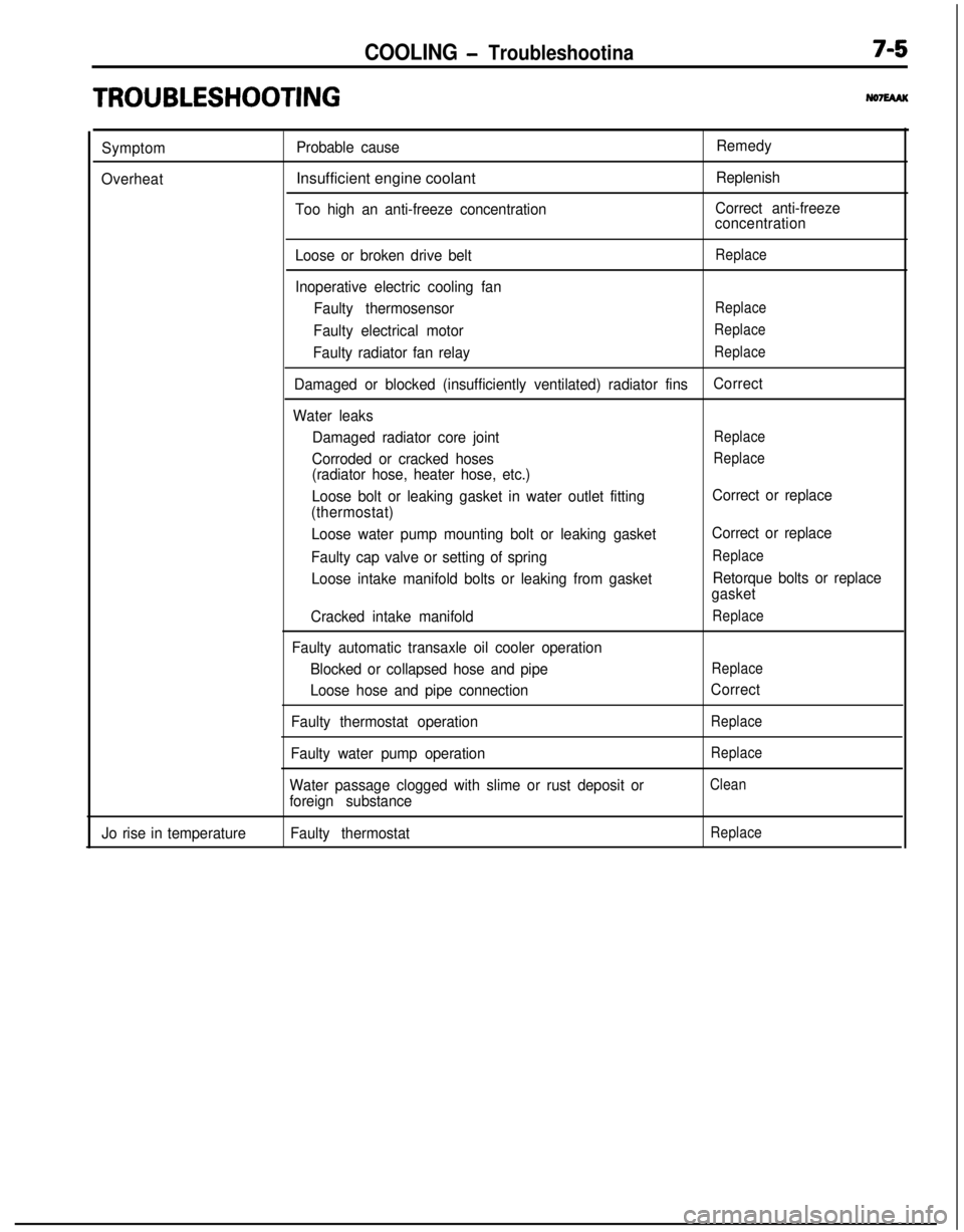
TRO,UBLESHOOTlNG
Symptom
OverheatProbable causeInsufficient engine coolant
Too high an anti-freeze concentrationRemedy
Replenish
Correct anti-freeze
concentration
Loose or broken drive belt
Replace
Inoperative electric cooling fan
Faulty thermosensor
Replace
Faulty electrical motorReplace
Faulty radiator fan relayReplace
Damaged or blocked (insufficiently ventilated) radiator finsCorrect
Water leaks
Damaged radiator core joint
Replace
Corroded or cracked hosesReplace
(radiator hose, heater hose, etc.)
Loose bolt or leaking gasket in water outlet fitting
(thermostat)
Loose water pump mounting bolt or leaking gasket
Faulty cap valve or setting of spring
Loose intake manifold bolts or leaking from gasket
Cracked intake manifold
Faulty automatic transaxle oil cooler operation
Blocked or collapsed hose and pipe
Loose hose and pipe connection
Faulty thermostat operation
Faulty water pump operation
Water passage clogged with slime or rust deposit or
foreign substanceCorrect or replace
Correct or replace
Replace
Retorque bolts or replace
gasket
Replace
Replace
Correct
Replace
Replace
Clean
Jo rise in temperatureFaulty thermostatReplace
Page 255 of 1216
COOLING - Troubleshooting7A7
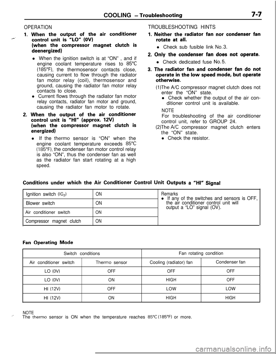
OPERATION
1. When the output of the air conditioner*--control unit is “LO” (OV)(when the
compressor magnet clutch isdeenergized)
l When the ignition switch is at “ON” , and if
engine coolant temperature rises to
85°C
(185”F), the thermosensor contacts close,
causing current to flow through the radiator
fan motor relay (coil), thermosensor and
ground, causing the radiator fan motor relay
contacts to close.
l Current flows through the radiator fan motor
relay contacts, radiator fan motor and ground,causing the radiator fan motor to rotate.
2. When the output of the air conditioner
control unit is “HI” (approx. 12V)(when the
compressor magnet clutch is
energized)l If the therm0 sensor is “ON” when the
engine coolant temperature exceeds
85°C
(185°F). the condenser fan motor control relay
is also “ON”, thus the condenser fan as well
as the radiator fan start rotating at a high
speed.
TROUBLESHOOTING HINTS
1. Neither the radiator fan nor condenser fanrotate at
all.l Check sub fusible link
No.3.
2. Only the condenser fan does not operate.l Check dedicated fuse
No.5.
3. The radiator fan and condenser fan do notoperate
in the low speed mode, but operateotherwise.
(1)The A/C compressor magnet clutch does not
enter the “ON” state.
l Check whether the output of the air con-
ditioner control unit is available.
NOTEFor troubleshooting of the air conditioner
control unit, refer to GROUP 24.
(2)The A/C compressor magnet clutch enters
the “ON” state.
l Check the resistor.Conditions
under which the Air Conditioner Control Unit Outputs a “HI” Signal
Ignition switch (IG2)
Blower switchAir conditioner switch
Compressor magnet clutch
ON
ON
ON
ON
Remarksl If any of the switches and sensors is OFF,
the air conditioner control unit will
output a “LO” signal (OV).
Fan Operating Mode
Switch conditions
Air conditioner switch
Therm0 sensor
LO
(OV)OFFLO
(OV)ONHI
(12V)OFFHI
(12V)ONFan rotating condition
Cooling (radiator) fanCondenser fan
OFFOFF
HIGHOFF
LOWLOW
HIGHHIGH
NOTE
_-The therm0 sensor is ON when the temperature reaches 85°C (185°F) or more.
Page 256 of 1216
7-8COOLING - Service Adjustment Procedures
04DooE
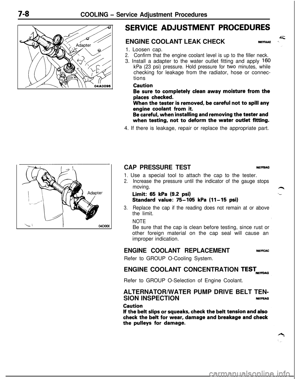
SERVICE ADJUSTMENT PROCEDURESENGINE COOLANT LEAK CHECK
NO7FAAE1. Loosen cap.
2.Confirm that the engine coolant level is up to the filler neck.3. Install a adapter to the water outlet fitting and apply
160
kPa (23 psi) pressure. Hold pressure for tvvo minutes, whilechecking for leakage from the radiator, hose or connec-
tionsCaution
Be sure to completely clean away moisture from the
places checked.When the tester
is removed, be careful not to spill anyengine coolant from
it.
Be careful, when installing and removing the tester andwhen testing, not
to deform the water outlet fitting.
4. If there is leakage, repair or replace the appropriate part.
CAP PRESSURE TESTNO’IFBAG
1. Use a special tool to attach the cap to the tester.
2.Increase the pressure until the indicator of the gauge stops
moving.Limit:
65 kPa (9.2 psi)Standard value:
75-105 kPa (11-15 psi)
3.Replace the cap if the reading does not remain at or abovethe limit.
NOTEBe sure that the cap is clean before testing, since rust or
other foreign material on the cap seal will cause an
improper indication.
ENGINE COOLANT REPLACEMENTRefer to GROUP O-Cooling System.NO’IFCACENGINE COOLANT CONCENTRATION
TESTmAGRefer to GROUP O-Selection of Engine Coolant.
ALTERNATOR/WATER PUMP DRIVE BELT TEN-
SION INSPECTION
NO7FEAGCaution
If the belt slips or squeaks, check the belt tension and also
check the belt for wear, damage and breakage and checkthe
pulleys for damage.
Page 260 of 1216
7-12COOLING - Radiator
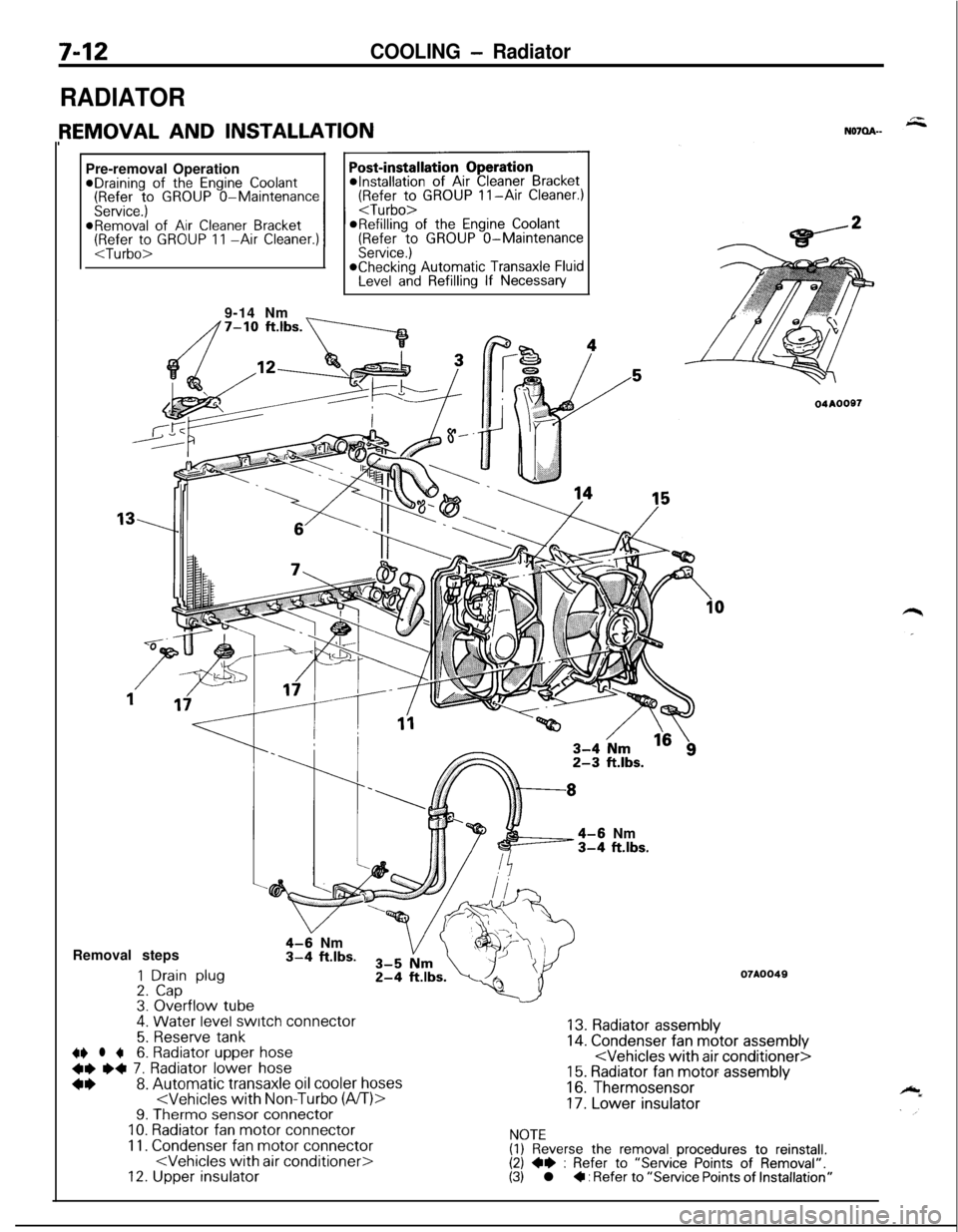
RADIATORPre-removal Operation
@Draining of the Engine Coolant(Refer to GROUP O-Maintenance(Refer to GROUP II-Air Cleaner.)
Service.)
I I
@Removal of Air Cleaner BracketORefilling of the Engine Coolant(Refer to GROUP 11 -Air Cleaner.)(Refer to GROUP O-MaintenanceService.)*Checking Automatic Transaxle FluidLevel and Refilling If Necessary
9-14 Nm
_
4-6 Nm3-4 ft.lbs.Removal steps
1 Drain plug2. Cap3. Overflow tube.
4-9 Nm3-4 ft.lbs.
4. Water level switch connector
5. Reserve tank~~ l +6. Radiator upper hose
+e e+ 7. Radiator lower hose
*I)8. Automatic transaxle oil cooler hoses9. Therm0 sensor connectorIO. Radiator fan motor connector
11. Condenser fan motor connector12. Upper insulator
04AOOS7
07A0049
13. Radiator assembly14. Condenser fan motor assembly15. Radiator fan motor assembly
16. Thermosensor
17. Lower insulator
NOTE(1) Reverse the removal procedures to reinstall.(2) +e : Refer to “Service Points of Removal”.(3) l + : Refer to “Service Points of Installation”
Page 265 of 1216
COOLING - Water Pump <1.8L Engine>
WATER PUMP 4.8L Engine>
7-17
- REMOVAL AND INSTALLATION
c.
-_*Draining of
the Engine Coolant(Refer to GROUP O-Maintenance
Post-installation Operation
l installation of the Under Cover@Supplying of the Engine Coolant(Refer to GROUP O-MaintenanceService.)@Engine Adjustment(RR:; to GROUP g-Engine Adjust-
8-10 Nm6-7 ftlbs.
48NOlMB-A
30-40 Nm
22-2g Fbs.
0
60-80 Nm43-58 ft.lbs.5-18
Nm1-13 ft.lbs.18-22 NmRemoval steps13-15 ft.lbs.
1. Clamp part of hoses (Power steering)4+2. Engine mount bracketl +3. Drive belt (Air conditioner)I)+ 4. Drive belt (Power steering)
4+ l + 5. Drive belt
7. Water pump pulleyWater pump pulleyDamper pullevAdapter. ’Crank shaft pulley.
OlAO566
(Powersteering)
6. Tension tx~llev bra&&I\lnTFr--‘--I -‘--‘.--I.VIL(I) Reverse the removal procedures to reinstall.I?\ CI Refer tn “Smvirr rh:-*- -‘ D---./al”,\-, --. I.VIw, .”..-..,u; r”llllb “I “allI”\(3) +4 : Refer to “Service Points nf Instalk_ - .,.__ -. _.._ .-Jion”.
Page 269 of 1216
COOLING - Water Pump <2.0L DOHC Engine>7-21WATER PUMP <2.0L DOHC Engine>
--- REMOVAL AND INSTALLATION
No7Ms-B
_Pre-removal Operation
@Removal of the Under Coverl Draining of the Engine Coolant(Refer to GROUP O-MaintenanceService.)
50-65 Nm136-47 ft.lbs.
60-60 Nm
Post-installation Operation
l installation of the Under Coverl supplying of the Engine Coolant(Refer to GROUP O-MaintenanceService.)*Engine Adjustment
(Ri+&; to GROUP g-Engine Adjust-
lo-12 Nm
7-9 ft.lbs. 43-5
31-4
III-40 Nm!-29 ft.lbs.17-26
12-19OlAO560
20-27 Nm14-20 ft.lbs.
23-27 Nm
17-20 ft.lbs.
”20-’ 30 Nm” .““*wY--
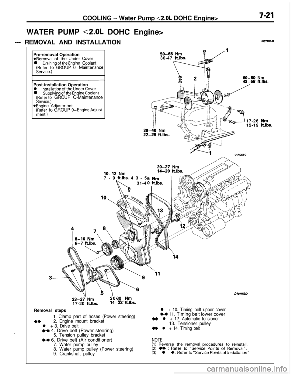
-~ . .14-22 ft.ll3s.Removal steps
I. Clamp part of hoses (Power steering)
+*2. Engine mount bracket
l + 3. Drive belte+ 4. Drive belt (Power steering)5. Tension pulley bracket
I)4 6. Drive belt (Air conditioner)7. Water pump pulley
8. Water pump pulley (Power steering)
9. Crankshaft pulley
l + 10. Timing belt upper coverI)4 11. Timing belt lower cover+I) l + 12. Automatic tensioner13. Tensioner pulley
+I) l + 14. Timing belt
NOTE(1) Reverse the removal procedures to reinstall.(2) +e : Refer to “Service Points of Removal”.(3) l 4 : Refer to “Service Points of Installation”
,“k.