1991 MITSUBISHI ECLIPSE drain bolt
[x] Cancel search: drain boltPage 660 of 1216

19-12STEERING - Service Adjustment Procedures
Pressure ofWater pump
pulleyOlA0059Fluid fluctuation
While engine
runningWhile enginestopped13uo139
Return hoseVinyl hose
x ,3Ao,42-
V-BELT TENSION CHECKNlSFliAl
1.Check to be sure that the belt is not damaged and that the
V-belt is correctly attached to the groove of the pulley.
NOTE, If there is abnormal noise or belt slippage, check the belt
tension and check for unusual wear or abrasion, or damage,
of the
pullev contact surface, and for scars or scratches onthe
pulley.2.
Press in V-belt at the illustrated position with about 100 N
(22 Ibs.) and measure deflection.
Standard value: 6-9 mm
1.26.35 in.)
3. If there is a deviation from the standard value range, make
an adjustment of the belt tension by following the procedures
described below.
(1) Loosen bolts A, B and C (for holding the oil pump).
(2) Place a bar or similar object against the body of the oil
pump, and, while manually providing the suitable
amount of tension, adjust the amount of
flexion of the
belt.
(3) Tighten bolts A, B and C (for holding the oil pump).
(4) Check the amount of flexion of the belt; readjust if
necessary.
CautionThe check should be made after turning the engine
one time or more in the regular direction of rotation (tothe
dght).
FLUID LEVEL CHECKNlSFIAI
1.Park the vehicle on a flat, level surface, startthe engine, andthen turn the steering wheel several times to raise the
temperature of the fluid to approximately
50-60°C
(122-140°F).2. With the engine running, turn the wheel all the way to the
left and right several times.3. Check the fluid in the oil reservoir for foaming or milkiness.
Check the difference of the fluid level when the engine is
stopped, and while it is running. If the fluid level changes
considerably, air bleeding should be done.
FLUID REPLACEMENTNlSFJAJ
1.Raise the front wheels on a jack, and then support them with
rigid racks.2. Disconnect the return hose connection.
3.Connect a vinyl hose to the return hose, and drain the oil into
a container.
Page 676 of 1216

19-28STEERING - Power Steering Gear Box
POWER STEERING GEAR BOXREMOVAL AND INSTALLATION
-
NlSPA--
Pre-removal Operation@Draining of the Power Steering Fluid@Removal of Transfer:1&&r:, GROUP 21 -Transfer.)50-65 Nm36-47 ft.lbs.
I/a
Post-installation Operationl Installation of Transfer(:zD:” GROUP 21 -Transfer.)
l SSy,lying of the Power Steeringl Bleedino of the Power Steering
Fluid
Liie(Refer to P.19-13.1l khecking of Steering Wheel Posi-tion with Wheels Straight Ahead*Adjustment of the Front Wheel
Alignment
(Refer to GROUP Z-Service Ad-
justment Procedures.)
Removal steps1.
“,;;rt assembly and gear box connecting
bolt
2. Connection for return tube
3. Connection for pressure hose
4. Cotter pin
5.
Aft-cd end and knuckle connecting
4I)f3: H,“a:od end
8. Stabilizer bar bracket
9. Front roll stopper mounting bolt10. Center member rear mounting bolt
4411. Front exhaust pipe
l + 13. Mounting rubber
(I) Reverse the removal procedures to reinstall.(2) +e : Refer to “Service Points of Removal”.(3) .* : Refer to “Service Points of Installation”.(4) q : Non-reusable parts(4) lli
3oh2 Nm22-30 ftlba.^a-aa I.au-IUU NrnI
IO-15 Nm22-29
ft.lbs.
15-20 Nm15-20 Nm
11-14 ft.lbs.
13A027612-18 Nm
A-34 IUm
K-
1 j-+ft.lbs.
:II I-.5
/ .2!
i!!1
NOTEW-W Nm43-58
ft.lbs.13A0353
Page 703 of 1216

MANUAL TRANSAXLE
Part name
Spacer
(For adjustment of differential case preload)
Spacer
(For adjustment of differential pinion backlash)
TORQUE SPECIFICATIONSThickness mm (in.)
1.22 f.0480)
1.25 (.0492)
0.75-0.82
(.0295-.0323)
0.83-0.92
(.0327-.0362)
0.93- 1 .oo
(.0366-.0394)
1.01-1.08
(.0398-.0425)
1.09-1.16
(.0429-.0457)Identification
symbol
GM
-
-
-
-Part No.
MA180862MA1
80866MA1 80875MA1 86876
Items
Nm
Shift lever to lever (A)
19-28
Lever (A) to bracket assembly
17-26
Drain plug
30-35Filler plug
30-35Starter motor mounting bolt
27-34
Transaxle bracket
60-80Shift lever knob
4.5-7.5
Shift cable and select cable to body9-14
Shift lever assembly to body
9-14
Automatic seat belt guide ring attaching bolt17-26
Clutch release cylinder mounting bolt
15-22
Clutch tube to transaxle assembly
15-22
Transaxle mount bracket to transaxle
60-80Shift cable and select cable to transaxle15-22
Under cover
9-13
Transaxle mounting bolt [12 mm (.47 in.) diameter
bolt143-55
Transaxle mounting bolt [IO mm (.40 in.) diameter
bolt130-35Transaxle mounting bolt
[8 mm (.31 in.) diameter bolt]IO-12Tie rod end to knuckle
24-35
Lower arm ball joint to knuckle
60-72Bell housing cover
IO-123ear cover bolt
15-223ackup light switch
30-35
loppet plug30-42
jpeedometer sleeve bolt3.0-5.0nput shaft lock nut
140-160ntermediate lock nut
gear
140-160
3everse idler gear shaft bolt
43-55
rransaxle case tightening bolt
35-42
stopper bracket bolt
15-22
qestrict ball assembly30-35
ft.lbs.
13-2012-18
22-25
22-25
20-2543-58
3-5
7-10
7-1012-19
11-16
11-1643-58
11-16
7-1032-39
22-25
7-9
17-25
43-52
7-9
11-1522-25
22-302.5-3.5
102-I 15
102-11532-39
26-3011-15
22-25
Page 769 of 1216

MANUAL TRANSAXLE
Lower arm ball joint to knuckle
Center bearing bracket installation bolts
Right member installation bolt (front)
Right member installation bolt (rear)
Transfer assembly mounting bolt
Poppet plug
Backup light switch
Restrict ball
Speedometer mounting bolt
Oil filler plug
Oil drain plug
Input shaft lock nut
Intermediate shaft lock nut
Center differential drive gear mounting bolt
Front differential drive gear mounting bolt
Stopper bracket mounting bolt
Reverse idler gear shaft mounting bolt
Reverse shift lever mounting bolt
Bearing retainer mounting bolt
Interlock plate mounting bolt
Center member mounting bolt
Irive shaft center bearing mounting bolt
Iriven bevel lock nutgear
Select lever assembly mounting bolt
3everse brake cone screw boltsNm
ft.Ibs. ”
60-7243-52 “
36-4626-33
80-10058-72
70-8051-58
55-6040-43
30-4222-30
30-3522-25
30-3522-25
3-52.5-3.5
30-3522-25
30-3522-25
140-160102-I 15
140-160102-I 15
70-8051-57
130-14095-10115-22
11-1543-55
32-39
15-22
11-1515-22
11-15
20-2715-19
60-8043-58
36-46
26-33
140-160101-11515-22
11-15
4.0-5.52.9-3.9
TRANSFERItems
Transfer assembly mounting bolt
Cover mounting bolt
Extension housing mounting bolt
Transfer cover mounting bolt
Transfer case adapter mounting bolt
Driven bevel gear lock nut
Hanger bracket mounting boltNm
ft.lbs.
55-6040-43
8-106-7
15-22
II-1535-42
26-3035-42
26-30
140-160102-I 15
15-22
11-15
LUBRICANTSN21CD.BItems
Specified lubricantQuantity lit. (qts.)
I
ITransmission oil
MOPAR Hypoid gear oil or equivalent,2.3 (2.43)
API classification GL-4 or higherITransfer oil
MOPAR Hypoid gear oil or equivalent,
API classification
GL-4 or higher0.6 (.63)
Page 860 of 1216

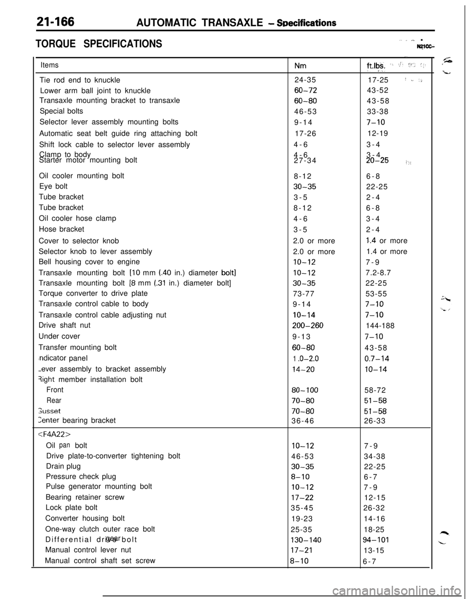
21-166AUTOMATIC TRANSAXLE - SDecifications
TORQUE SPECIFICATIONS,. _ ,,,_ .Nglcc-
ItemsTie rod end to knuckle
Lower arm ball joint to knuckle
Transaxle mounting bracket to transaxle
Special bolts
Selector lever assembly mounting bolts
Automatic seat belt guide ring attaching bolt
Shift lock cable to selector lever assembly
Clamp to body
Starter motor mounting bolt
Oil cooler mounting bolt
Eye bolt
Tube bracket
Tube bracket
Oil cooler hose clamp
Hose bracket
Cover to selector knob
Selector knob to lever assembly
Bell housing cover to engine
Transaxle mounting bolt
[lo mm l.40 in.) diameter bolt]Transaxle mounting bolt
[8 mm I.31 in.) diameter bolt]
Torque converter to drive plate
Transaxle control cable to body
Transaxle control cable adjusting nut
Drive shaft nut
Under cover
Transfer mounting boltndicator panel-ever assembly to bracket assembly
3ight member installation bolt
Front
Rear
;usset
Zenter bearing bracket
:l=4A22>Oil bolt
panDrive plate-to-converter tightening bolt
Drain plug
Pressure check plug
Pulse generator mounting bolt
Bearing retainer screw
Lock plate bolt
Converter housing bolt
One-way clutch outer race bolt
Differential drive bolt
gearManual control lever nut
Manual control shaft set screw
Nm24-35
60-72
60-8046-53
9-14
17-26
4-6
4-6
27-34
8-12
30-353-5
8-12
4-6
3-5
2.0 or more
2.0 or more
10-12
10-12
30-3573-77
9-14
IO-14
200-2609-13
60-80
1 .o-2.0
14-20
80- 100
70-80
70-8036-46
10-1246-53
30-35
8-10
IO-12
17-2235-45
19-23
25-35
130-14017-21
8-10
-.
ft*lgk+ ‘. St. :“.. (1.17-25
I ~. ‘,43-52
43-58
33-38
7-1012-19
3-4
3-4
20-25i::6-8
22-25
2-4
6-8
3-4
2-4
1..4 or more
1.4 or more
7-9
7.2-8.7
22-25
53-55
7-10
7-10144-188
7-1043-58
0.7-14
10-1458-72
51-58
51-5826-33
7-9
34-38
22-25
6-7
7-9
12-15
26-32
14-16
18-25
94-10113-15
6-7
Page 861 of 1216

AUTOMATIC TRANSAXLE - SeecificdionsItems
Inhibitor switch
Sprag rod support bolt
Pump housing-to-reaction shaft support
bolt
Oil assembly mounting bolt
pumpValve body bolt
Valve body assembly mounting bolt
Oil filter bolt
Speedometer sleeve locking plate bolt
End clutch cover
Kickdown lock nut
< F4A33.W4A33 >Air exhaust plug
Center bearing retainer stopper bolt
Differential drive bolt
gearDifferential front bearing bolt
capDifferential rear bearing retainer bolt
End clutch cover bolt
Front bearing retainer bolt
gearIdler shaft lock bolt
Inhibitor switch bolt
Kickdown servo lock nut
Manual control lever nut
Manual control shaft set screw
Oil drain bolt
Oil filter bolt
Oil level guide bolt
gaugeOil bolt
panOil check plug
pressureOil assembly mounting bolt
pumpOil pump bolt
Output bearing retainer bolt
Output flange bearing retainer bolt
Nm
IO-12
20-27
10-1215-22
4-6
10-125-7
3-5
6-8
25-32
30-354-6
70-80
10-12
130-140
60-80
30-40
10-1243-55
10-1231-44
IO-1225-32
17-21
8-10
30-355-7
20-27
10-124-6
19-23
10-12
20-2717-22
,I
‘ft.lbs.
7-915-19
,,
7-911-15
3-4
7-94-5
2-4
5-6
18-23
22-25
3-4
51-57
7-9
94-10143-58
22-29
7-9
32-39
7-922-32
7-9
18-23
12-15
6-7
-_22-25
4-5
15-19
7-93-4
13-17
7-9
15-19
12-16"/Parking rod support bolt
20-2715-19Pulse generator bolt
IO-127-9Roll stopper bracket bolt
43-55
32-39
'Shift control cable bracket bolt
20-2715-19Speedometer gear locking plate bolt
4-6
3-4
Transaxle mount bracket bolt
60-80$-,58Valve body assembly mounting bolt
10-127-9
Valve body bolt
4-6
3-4
-.
Page 862 of 1216

21-168AUTOMATIC TRANSAXLE - Specifications
-TRANSFER
ItemsNmCover mounting bolt
4-6
Driven bevel gear lock nut
140-160Extension housing mounting bolt
15-22Oil drain plug
30-35Oil filler plug
30-35Transfer case adapter mounting bolt
35-42
Transfer cover mounting bolt
35-42ft.lbs.
‘3-4
.
162-115 ‘i
‘11-1522-25
22-25
26-30
36-30
LUBRICANTSW1CD-C
ItemsSpecified lubricantQuantity
Transaxle fluidliters
(qts.) MOPAR ATF PLUS (Automatic transmission 6.1 (6.4)
or equivalent
:‘,Key interlock cableMOPAR Multi-mileage Lubricant PartAs required
Select lever assemblyNo. 2525035 or equivalent
Bushing, sleeve, spring,
pushbutton and lock cam
Drive shaft oil seal lipMOPAR ATF PLUS (Automatic transmission As required
fluid type 7176) or Dia ATF SP
or equivalent
SEALANTS AND ADHESIVESN2lcE-c
ItemsTransaxle case gasket
Bearing retainer screw bolts
Silicone grease
MOPAR Part
No.4318031 or MOPAR Part
No. 4318032 or equivalent
ItemsTransfer extension housing-Transfer adapter
Front bearing retainer bolts
Center differential flange bolts
Air breatherSpecified sealants and adhesives
MITSUBISHI Genuine Part
No.997740 or
equivalent::t;p,
MOPAR Part
No.4318031. or MOPAR ‘Part”’ ‘~’ “,“iNo.4318032 or equivalent’ ‘. :“’MOPAR Part No.4318025 or equivalent
Page 918 of 1216

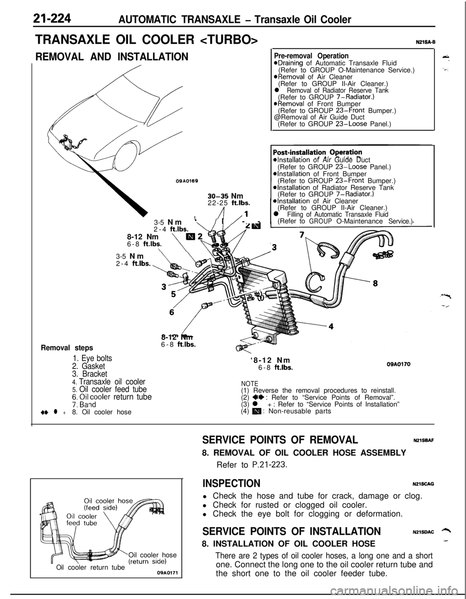
21-224AUTOMATIC TRANSAXLE - Transaxle Oil Cooler
TRANSAXLE OIL COOLER
REMOVAL AND INSTALLATION
OQA01691
30-35 Nm
22-25 ft.lbs.
/I1’
Removal steps
1. Eye bolts
2. Gasket3-5 Nm
‘\/I/ --
2-4
ftlbs.8-12 Nm
m26-8 ft.lbs.\\
N21SA-B
Pre-removal OperationeDraining of Automatic Transaxle Fluid
(Refer to GROUP O-Maintenance Service.)
@Removal of Air Cleaner
(Refer to GROUP II-Air Cleaner.)
l Removal of Radiator Reserve Tank(Refer to GROUP 7-Radiator.)
@Removal of Front Bumper
(Refer to GROUP 23-Front Bumper.)
@Removal of Air Guide Duct
(Refer to GROUP
23-Loose Panel.)
*Installation of Air Guide Duct
(Refer to GROUP 23-Loose Panel.)*Installation of Front Bumper
(Refer to GROUP 23-Front Bumper.)@Installation of Radiator Reserve Tank
(Refer to GROUP 7-Radiator.)
*Installation of Air Cleaner
(Refer to GROUP II-Air Cleaner.)
l Filling of Automatic Transaxle Fluid(Refer toGROUPO-MaintenanceService.)3-5 Nm
2-4
ftlbs.8-12 Nm
6-8
ft.lbs.‘8-12 Nm
6-8
ftlbs.OBAOl703. Bracket
4. Transaxle oil cooler5. Oil cooler feed tubeNOTE(1) Reverse the removal procedures to reinstall.
7: ~i&~oler return tube(2) ++ : Refer to “Service Points of Removal”.
(3) l + : Refer to “Service Points of Installation”
+e l +8. Oil cooler hose(4) m : Non-reusable parts
Oil cooler hose
Oilcoolerreturn tube09A0171
&.
-=-.
SERVICE POINTS OF REMOVALNZlSBAF8. REMOVAL OF OIL COOLER HOSE ASSEMBLY
Refer to
P.21-223.
INSPECTIONN2lSCAGl Check the hose and tube for crack, damage or clog.
l Check for rusted or clogged oil cooler.
l Check the eye bolt for clogging or deformation.
SERVICE POINTS OF INSTALLATIONN2lSDAC ‘-+8. INSTALLATION OF OIL COOLER HOSE_
There are 2 types of oil cooler hoses, a long one and a shortone. Connect the long one to the oil cooler return tube and
the short one to the oil cooler feeder tube.