1991 MITSUBISHI ECLIPSE torque
[x] Cancel search: torquePage 853 of 1216

AUTOMATIC TRANSAXLE - Specifications
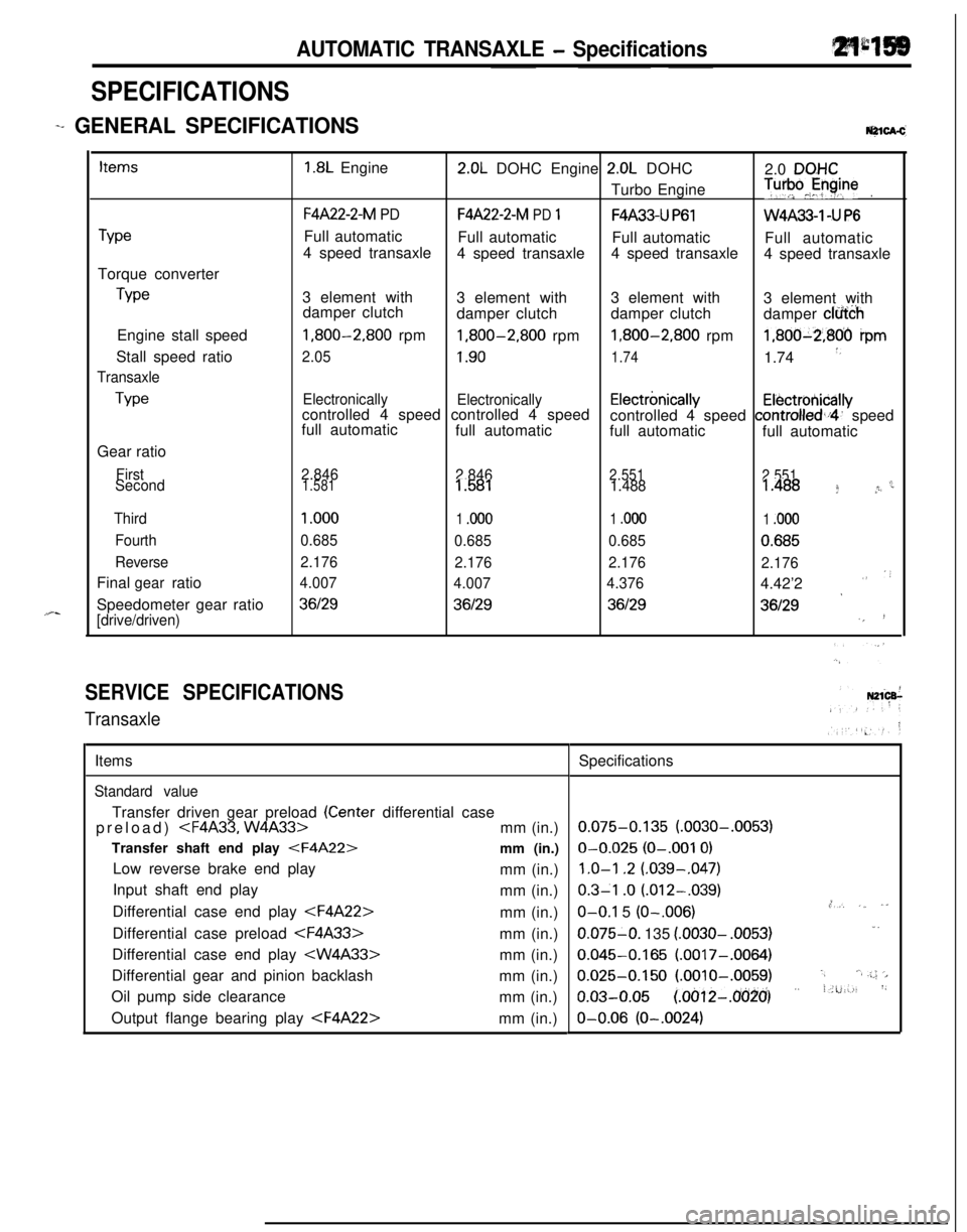
SPECIFICATIONS
-+ GENERAL [email protected]
TypeTorque converter
TypeEngine stall speed
Stall speed ratio
Transaxle
TypeGear ratio
First
Second
Third
Fourth
ReverseFinal ratio
gearSpeedometer gear ratio
[drive/driven)
1.8L Engine2.0L DOHC Engine 2.0L DOHC
2.0 DQHCTurbo Engine
T”‘pJyine.
F4A22-2-M PDF4A22-2-M PD 1F4A33-U P61W4A33-1 -U P6Full automatic
Full automatic
Full automatic
Full automatic
4 speed transaxle
4 speed transaxle4 speed transaxle
4 speed transaxle
3 element with
3 element with3 element with
3 element with
damper clutch
damper clutchdamper clutch
damper clfi&h
1,800-2,800 rpm1,800-2,800 rpm1,800-2,800 rpm1,800-2,806 ipm
2.051.901.741.74 *,
Electronically
Electronicallycontrolled 4 speed controlled 4 speedElectrbnicallyElectrotiicallyfull automaticcontrolled 4 speed controlled,i4’ speed
full automatic
full automatic
full automatic
2.846
2.8462.551
2.551c1.5811.5811.4881.488 f *r
1 .ooo
1 .ooo1 .ooo1 .ooo
0.685
0.6850.6850.685
2.176
2.1762.176
2.176
4.007
4.0074.3764.42’2
””
*36129361293612936129‘,!
SERVICE SPECIFICATIONS
TransaxleItems
Standard valueTransfer driven gear preload
(Center differential case
preload)
Transfer shaft end play
Low reverse brake end play
mm (in.)
Input shaft end play
mm (in.)
Differential case end play
Differential case preload
Differential case end play
Differential gear and pinion backlash
mm (in.)
Oil pump side clearance
mm (in.)
Output flange bearing play
0.075-0.135 (.0030-.0053)O-0.025
(O-.001 0)
1.0-l .2 (.039-,047)
0.3-l .o (.012-.039).,O-O.1 5 (O-.006),*, ,_ ,”0.075-O. 135
(.0030- .0053)1.
0.045-0.165 (.0017-.0064)
0.025-0.150 (.OOlO-.0059).,‘.a .;.; ‘>
o.03-o.05 (~oo12-~o(j~o’) ” i.u:-., ‘~O-0.06
(O-.0024)
Page 854 of 1216

21-160AUTOMATIC TRANSAXLE - Specifidons
ItemsOutput flange bearing end play
Front clutch end play
End clutch end play
Front clutch end play
Rear clutch end play
End clutch end play
Transfer idler gear preload
Front output shaft end play
Transfer
Driven bevel gear starting torque
Bevel gear backlashNm
(ft.lbs.)Nm
(ft.lbs.)mm (in.)
IALVE BODY SPRING IDENTIFICATION CHARTPart name
Regulator valve spring
l-2 shift valve spring
Pressure control valve spring
Rear clutch exhaust valve spring
End clutch valve spring
2-3 shift valve spring
N-R control valve spring
Reducing valve spring
Line relief spring
Torque converter valve spring
Shift control valve spring
FFyl;;;lutch control valve spring
SPACER SETWire diameter
mm (in.)
1.4 (055)
0.6 (024)
0.45 (0177)
0.7 (028)
0.6
(.024)0.8
(.031)0.7 (028)
1.2 (047)
1.0 l.039)
1.3 (051)
0.5 (020)
0.7
(.028)Outside dia.
mm (in.)
15i.59)
7.6
t.299)
7.6(.299)
6.8(.268)
6.6(260)
7.0(276)
9.2(.362)
8.9(350)
7.0(276)
9.0(.354)
5.7(224)
6.2(.244)
IPart name
Spacer set
(for adjustment of input shaft end play)Specifications
o-0.09 (d-.0035); . ,i f 1, ,i’.” :,li
0.7-0.9 (.028-.035)
0.4-0.6 (.016-.024)
0.4-0.65 (.016-.026)
0.8-I .O (.032-.039)
1.0-I .2 (.039-.047)
0.60-0.85 (.024-.034)
0.8
(1)
0.01-0.03 (.0004-.0012)
0.055-0.115 (.0022-.0045)
1.7-2.5 (1.23-1.81)
1.0-I .7 (0.72- 1.23)
0.08-0.13 (.0031-.0051)
Lengthmm (in.)
52 (2.05)
26.6 (1.047)
21.3
(.839)27.4 (1.079)
24.4
(.961)27.5 (1.883)
32.1 (1.264)
29.5 (1.161)
17.3
(.681)22.6
i.890)26.8 (1.055)
14.2
(.559)No. of turns
11.5
13.5
8.5
12.5
15.5
15.5
‘4
8.5
’-*12.5
10
9.5
’22
9.5I
Thicknessmm (in.) Part No. “’
1.4(055).1.0l.040)MD997854
1.4(.055),
1.2(047)MD997847
’1.8(.071),
1.4l.055)MD997848::!1.8
(.071), 1.6 (.063)fQlD997849 ” .’
2.2(.087),
1.8(.071)MD997850
2.2(.087),2.0(.079)MD997851h2.6(.102),2.2(.087)MD997852“-2.6(.102),2.4i.095)M D997853
Page 860 of 1216

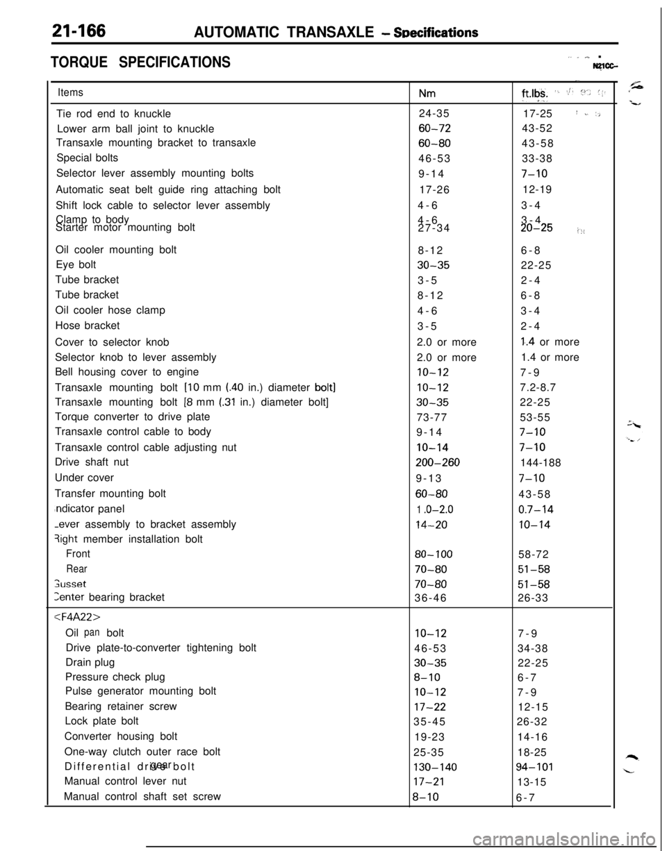
21-166AUTOMATIC TRANSAXLE - SDecifications
TORQUE SPECIFICATIONS,. _ ,,,_ .Nglcc-
ItemsTie rod end to knuckle
Lower arm ball joint to knuckle
Transaxle mounting bracket to transaxle
Special bolts
Selector lever assembly mounting bolts
Automatic seat belt guide ring attaching bolt
Shift lock cable to selector lever assembly
Clamp to body
Starter motor mounting bolt
Oil cooler mounting bolt
Eye bolt
Tube bracket
Tube bracket
Oil cooler hose clamp
Hose bracket
Cover to selector knob
Selector knob to lever assembly
Bell housing cover to engine
Transaxle mounting bolt
[lo mm l.40 in.) diameter bolt]Transaxle mounting bolt
[8 mm I.31 in.) diameter bolt]
Torque converter to drive plate
Transaxle control cable to body
Transaxle control cable adjusting nut
Drive shaft nut
Under cover
Transfer mounting boltndicator panel-ever assembly to bracket assembly
3ight member installation bolt
Front
Rear
;usset
Zenter bearing bracket
:l=4A22>Oil bolt
panDrive plate-to-converter tightening bolt
Drain plug
Pressure check plug
Pulse generator mounting bolt
Bearing retainer screw
Lock plate bolt
Converter housing bolt
One-way clutch outer race bolt
Differential drive bolt
gearManual control lever nut
Manual control shaft set screw
Nm24-35
60-72
60-8046-53
9-14
17-26
4-6
4-6
27-34
8-12
30-353-5
8-12
4-6
3-5
2.0 or more
2.0 or more
10-12
10-12
30-3573-77
9-14
IO-14
200-2609-13
60-80
1 .o-2.0
14-20
80- 100
70-80
70-8036-46
10-1246-53
30-35
8-10
IO-12
17-2235-45
19-23
25-35
130-14017-21
8-10
-.
ft*lgk+ ‘. St. :“.. (1.17-25
I ~. ‘,43-52
43-58
33-38
7-1012-19
3-4
3-4
20-25i::6-8
22-25
2-4
6-8
3-4
2-4
1..4 or more
1.4 or more
7-9
7.2-8.7
22-25
53-55
7-10
7-10144-188
7-1043-58
0.7-14
10-1458-72
51-58
51-5826-33
7-9
34-38
22-25
6-7
7-9
12-15
26-32
14-16
18-25
94-10113-15
6-7
Page 863 of 1216

AUTOMATIC TRANSAXLE - Special Tools
SPECIAL TOOLSN2lDA-C
ToolNumber
NameI Use
easurementorque (W4A33)
Page 865 of 1216

AUTOMATIC TRANSAXLE - SDecial Tools21~171
MD998341Kickdown servo toolRemoval and installation of kickdown servoWrench adapter
“6”Removal and installation of transfer idler shaft
Installation of transfer shaft rear bearing and
M D998367Snap ring installerAssembly of the end clutch
eanng remover
Installation of drive shaft oil seal (W4A33)
Wrench adapterMeasurement of transfer driven bevel geardrive torque (W4A33)
Page 872 of 1216

21-178AUTOMATIC TRANSAXLE - Troubleshooting
09P0010Fluid level must be
within this range.09PoOll
0”
Two302
DIAGNOSIS AND TEST
FLUID LEVEL AND CONDITION1. Drive until the fluid temperature reaches the usual tem-
perature
[70-80°C (160- 18O”F)I.2. Place vehicle on level floor.
3. Move selector lever sequentially to every position to fill
torque converter and hydraulic circuit with fluid, then place
lever in “N” Neutral position. This operation is necessary tobe sure that fluid level check is accurate.
4. Before removing dipstick, wipe all dirt from area around
dipstick. Then take out the dipstick and check the conditionof the fluid.
The transaxle should be overhauled under the following
conditions.l If there is a “burning” odor.
l If the fluid color has become noticeably blacker.
lIf there is a noticeably great amount of metal particles inthe fluid.
5.Check to see if fluid level is in “HOT” range on dipstick. If
fluid level is low, add automatic transaxle fluid until level
reaches “HOT” range.
Low fluid level can cause a variety of conditions because itallows pump to take in air along with fluid. Air trapped in
hydraulic circuit forms bubbles which make fluid spongy.
Therefore, pressures will be erratic.
Improper filling can also raise fluid level too high. When
transaxle has too much fluid, gears churn up foam and
cause same conditions which occur with low fluid level,
resulting in accelerated deterioration of automatic transaxle
fluid.In either case, air bubbles can cause overheating, fluid
oxidation, which can interfere with normal valve, clutch,
and servo operation. Foaming can also result in fluid
escaping from transaxle vent where it may be mistaken for
a leak.
6. Be sure to examine fluid on dipstick closely.
CONTROL CABLE
Whether control cable is properly adjusted can be confirmed bychecking whether inhibitor switch is performing well.
1. Apply parking brakes and service brakes securely.
2. Place selector lever to “R” range.
3. Set ignition key to “ST” position.
4. Slowly move the selector lever upward until it clicks as it
fits in notch of “P” range. If starter motor operates when
lever makes a click, “P” position is correct.
5.Then slowly move selector lever to “N” range by the same
procedure as in foregoing paragraph. If starter motor
operates when selector lever fits in “N”, “N” position is
correct.6. Also check to be sure the vehicle doesn’t begin to move
and the lever doesn’t stop between P-R-N-D.
7. The control cable is properly adjusted if, as described
above, the starter motor starts at both the “P” range and
the “N” range.
Page 890 of 1216

21-196AUTOMATIC TRANSAXLE - TroubleshootingStandard Oil Pressure Table
F4A22
Standard oil pressure kPa (psi)Conditions
1NIdlingNeutral360-490(51-70)
2DIdling2nd gear360-490(51-70)
3&ON,Approx.360-4902,5004th gear(51-70)830-900830-900(118-128) -(118-128) -
830-900830-900830-900350-450(118-128)(118-128)(118-128) -(50-6434(SWF)oFF, ,A2pp5boox.3rd gear360-490(51-70)
52Approx.2nd gear360-4902,500(51-70)830-900(118-128)-
6LAp”60”.1st gear360-490(51-70)-I-
1,640-2.240(233-319)-
l-41,500 (213)or more1 or more I
TStandard oil pressure kPa (psi)
0Kickdown
brakepressure
(Release)
@IFrontclutchpressure
0Rearclutchpressure
c3Endclutchpressure
0Low-reverse
brakepressure
00ShiftpositionReducing KickM;vnpressurepressure
-l---l
(APPM
Neutral !r$I$$ -
c3Torque-converter
pressure
h
No.SelectleverpositionEnginespeed
m
Idling
IdlingApprox.2,500Approx.
1,000Approx.2,500
N-
-
LI
*D730-830(104-118)2nd gear (51-68)I I360-480 100-210(14-30)-
830-900(118-128)(SWFON,-
830-900(118-128)830-900(118-128)4SW%FF:830-900(118-128)830-900(118-128)
2450-650(64-92)
*
450-650(64-92)
830-900(118-128)
830-900(118-128)
-
-6,640-2.24C
(233-319),640-2.24C(233-319)I ,640-2.24C(233-319)III
17-
1.500 (213)or more1,500 (213)or more1,500 (213)or more
NOTEmust be 10 kPa (1.4 psi) or less.SW-ON: Switch ON the overdrive control switchSW-OFF: Switch OFF the overdrive control switchI+: Hydraulic pressure is generated, but not the standard value.
Page 892 of 1216

21-198AUTOMATIC TRANSAXLE - Troubleshooting
Trouble symptom6. improper
low-
reverse brake
pressure
7. Improper torque
converter pressureProbable causea.O-ring between valve body and
transaxle damaged or missing
b.Looseness of valve body tighten-
ing part
c.Functional malfunction of the
valve body assembly
d.Malfunction of the O-ring 0 of thelow-reverse brake piston or the
O-ring
0 of the retainer (Refer tothe figure below.)
a.Sticking of the damper clutch
control solenoid valve (DCCSV) or
the damper clutch control valve.
b.Clogging or leaking of the oil
cooler and/or piping
2.Damaged seal ring @of the input
shaft (Refer to the figure below.)
3.Malfunction of the torque conver-
ter
Remedy
a.Remove the valve body assembly and check to
be sure that the O-ring at the upper surface of
the upper valve body is not
missinor dam-
aged; install or replace the O-ring i7necessary.
b.Tighten the valve body tightening bolt andinstallation bolt.
c.Replace the valve body assembly.
d.Disassemble the transaxle itself and check the
O-ring for damage; replace if there are cuts,
scars, scratches or damage.
a.Check the operation of the damper clutch
system and the DCCSV.
b.Repair or replace, as necessary, the cooler
and/or piping.
c.Disassemble the transaxle itself and check for
damage of the seal ring; replace the seal ring if
there is damage.
d.Replace the torque converter.
@D-ring@Seal ring
-OD-ring@Seal ring
(@Seal ring
@O-ring
1750437