Page 334 of 1216
S-50 ENGINE 4.8L Engine> -Rocker Arms, Rocker Arm Shafts and Camshaft
MD998443Lash adjuster
6EN248Apply sealant
DEN230
10 mm
3EN0044
9.INSTALLATION OF ROCKER ARM AND SHAFT ASSEM-
BLY(1) Insert the lash adjuster from below as illustrated, being
*-careful not to spill the diesel oil inside it. Then use the
+special tool to prevent adjuster from falling while
installing it.
(2) Place the rocker arm and shaft assembly on the cylinderhead and tighten the bearing cap bolt.
(3) Remove the special tool.
8.APPLICATION OF SEALANT TO SEMI-CIRCULAR PACK-
ING
Apply sealant on the periphery of the semi-circular packing.
Specified sealant: MOPAR Part No.4318034 or equiva-
lent
Page 335 of 1216
ENGINE <1.8L Engine> -Rocker Arms and Rocker Shafts
ROCKER ARMS AND ROCKER SHAFTS
RDISASSEMBLY AND REASSEMBLYNOSNE-A3EN0080
Disassembly steps
1. Rear camshaft bearing cap
2. Rocker arml 3. Wave washer
~~ 4. Camshaft bearing cap No. 45. Rocker shaft spring
l +6. Camshaft bearing cap No. 3~~ 7. Camshaft bearing cap No. 2l +8. Right rocker shaft
l 9. Left rocker shaft
10. Front bearing cap
lybeverse the disassembly procedures to reassemble.(2) l : Refer to “Service Points of Reassembly”.
Page 336 of 1216

7EN0064
IIENGINE
<1.8L Engine> -Rocker Arms and Rocker Shafts
SERVICE POINTS OF DISASSEMBLY
NOTEBefore disassembly, mark the rocker arm for
indentificahon.
INSPECTIONNoaNGAG
ROCKER ARM(1) Visually check the roller and replace if dent, damage, or
seizure is evident.
(2) Check roller for smooth rotation. Replace if it is binds or
there is an excessive play.
ICuts in rocker shafts(3) Check the inside diameter and replace the rocker arm if
damage or seizure is observed.SERVICE POINTS OF REASSEMBLYNOBNHBC
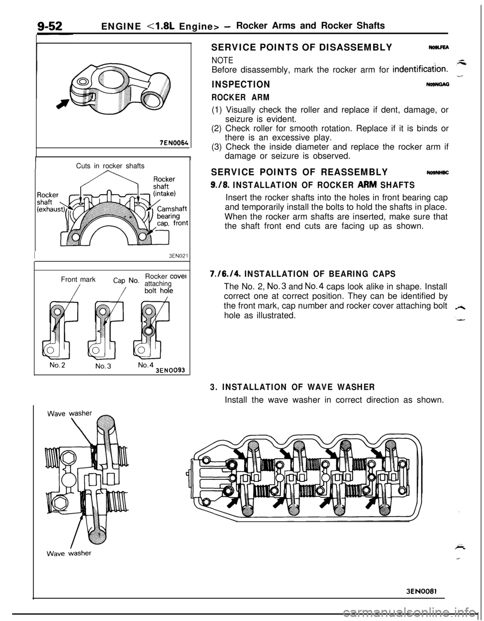
9./8. INSTALLATION OF ROCKER AeM SHAFTSInsert the rocker shafts into the holes in front bearing cap
and temporarily install the bolts to hold the shafts in place.
When the rocker arm shafts are inserted, make sure that
the shaft front end cuts are facing up as shown.
I3EN021Front mark
Cap No.Rocker cove1attaching
No.2No.3No.43EN0093
7./6./4. INSTALLATION OF BEARING CAPSThe No. 2, No.3 and No.4 caps look alike in shape. Install
correct one at correct position. They can be identified by
the front mark, cap number and rocker cover attaching bolt
hole as illustrated.
3. INSTALLATION OF WAVE WASHERInstall the wave washer in correct direction as shown.
3EN0081
Page 337 of 1216
ENGINE <1.8L Engine>- Cylinder Head and Valve9-53
CYLINDERHEADAND VALVE
-’DISASSEMBLY AND REASSEMBLYNDSPE-A
C;;d ;;g$;
51154 ftlbs.
&
, tP-----5
1g-.-a
105 y----2g&---l4
Disassembly steps
+e ~~I. Cylinder head bolts
2. Washer
3. Cylinder head4. Gasket
+e l +5. Retainer lock
6. Valve spring retainer
l + 7. Valve spring
~~ 8. Intakevalve+e e+ 9. Retainer lock10. Valve spring retainer
l a 11. Valve springl + 12. Exhaust valve+* l 4 13. Valve stem seall 4 14. Valve spring seat4I) l * 15. Valve stem seall + 16. Valve spring seat17. Intake valve guide
18. Exhaust valve guide
19. Intake valve seat20. Exhaust valve seatNOTE(I) Reverse the disassembly procedures to reassemble.(2) +e : Refer to “Service Points of Disassembly”.(3) ~~ : Refer to “Service Points of Reassembly”.(4) m : Non-reusable parts
3EN289
Page 338 of 1216
ENGINE - Cylinder Head and ValveSERVICE POINTS OF DISASSEMBLY
1. REMOVAL OF CYLINDER HEAD BOLTS
3EN123Front of engine (Timing belt side)
c
1 EN025
3EN324Loosen the bolts in the order shown.
Loosen them little by little and uniformly.
5./9. REMOVAL OF RETAINER LOCKS(1) Using the special
tool, remove the retainer locks.
(2) Keep the removed retainer locks valve by valve so that
they can be reinstalled in their original positions.
A
13.115. REMOVAL OF VALVE STEM SEALRemove the stem seals with pliers. Do not reuse the valve
stem seal.
Page 339 of 1216

ENGINE - Cylinder Head and Valve9-55
3EN026
w -w===j=Margin , EN034
Squareness
IFree length
INSPECTION
CYLINDER HEADNosocAMl Check the cylinder head for cracks, damage and engine
coolant leakage.l
Remove the scale, sealing compound and carbon deposits
completely. After cleaning oil passages, apply compressedair to make certain that the passages are clear.
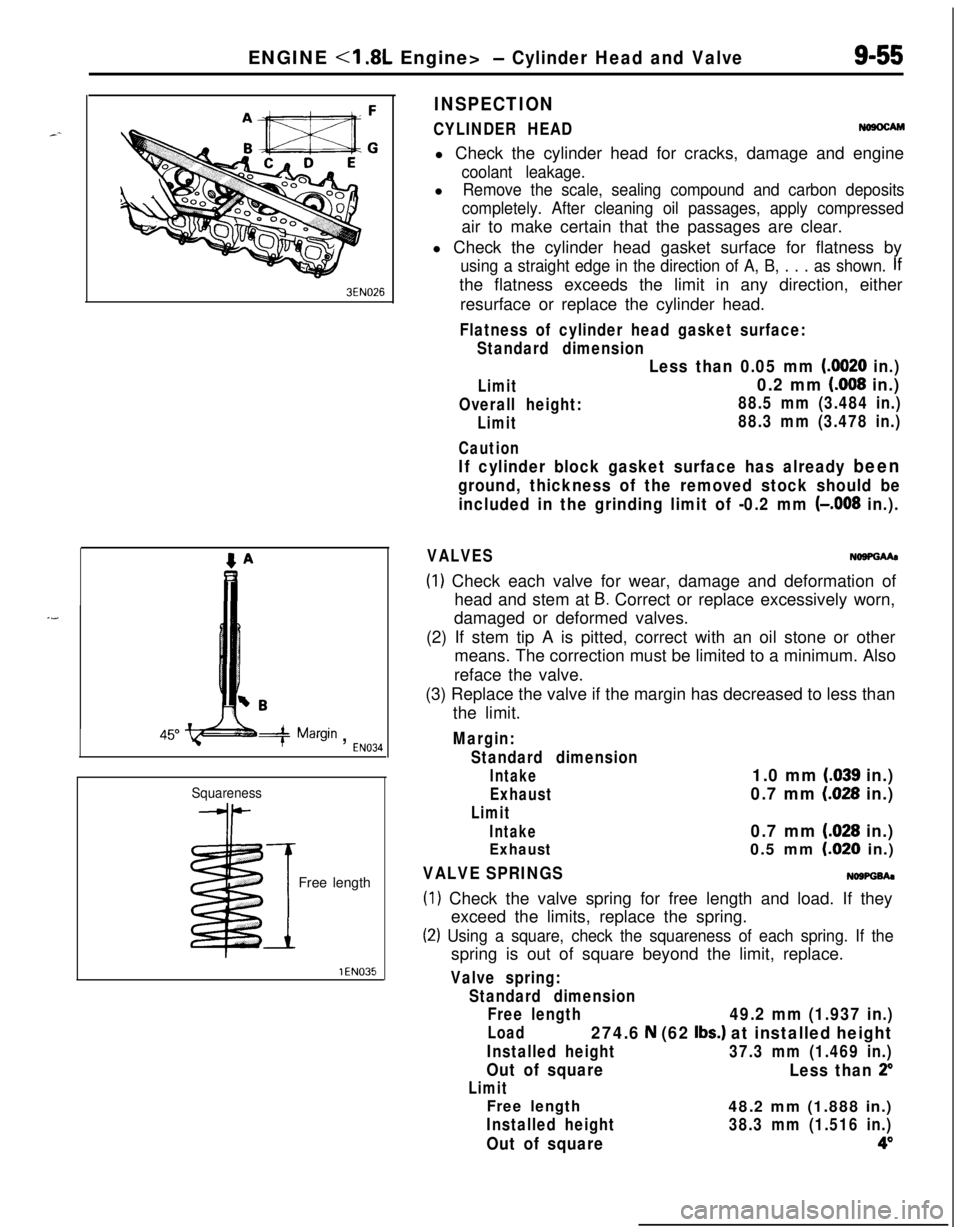
l Check the cylinder head gasket surface for flatness by
using a straight edge in the direction of A, B, . . . as shown. Ifthe flatness exceeds the limit in any direction, either
resurface or replace the cylinder head.
Flatness of cylinder head gasket surface:
Standard dimension
Limit
Overall height:
Limit
Caution
Less than 0.05 mm (0020 in.)
0.2 mm (008 in.)
88.5 mm (3.484 in.)
88.3 mm (3.478 in.)
If cylinder block gasket surface has already been
ground, thickness of the removed stock should be
included in the grinding limit of -0.2 mm
(-,008 in.).
VALVESNo9PGMa
(1) Check each valve for wear, damage and deformation of
head and stem at
B. Correct or replace excessively worn,
damaged or deformed valves.
(2) If stem tip A is pitted, correct with an oil stone or other
means. The correction must be limited to a minimum. Also
reface the valve.
(3) Replace the valve if the margin has decreased to less than
the limit.
Margin:
Standard dimension
Intake1.0 mm (.039 in.)
Exhaust0.7 mm (028 in.)
Limit
Intake0.7 mm (.028 in.)
Exhaust0.5 mm LO20 in.)
VALVE SPRINGSNOWGh
(1) Check the valve spring for free length and load. If they
exceed the limits, replace the spring.
(2) Using a square, check the squareness of each spring. If thespring is out of square beyond the limit, replace.
Valve spring:
Standard dimension
Free length
49.2 mm (1.937 in.)
Load274.6 N (62 Ibs.) at installed height
Installed height37.3 mm (1.469 in.)
Out of square
Less than 2”
Limit
Free length48.2 mm (1.888 in.)
Installed height38.3 mm (1.516 in.)
Out of square4”
Page 340 of 1216

9-56ENGINE <1.8L Engine> - Cylinder Head and ValveStem O.D.
YEN323
3EN0039
-I
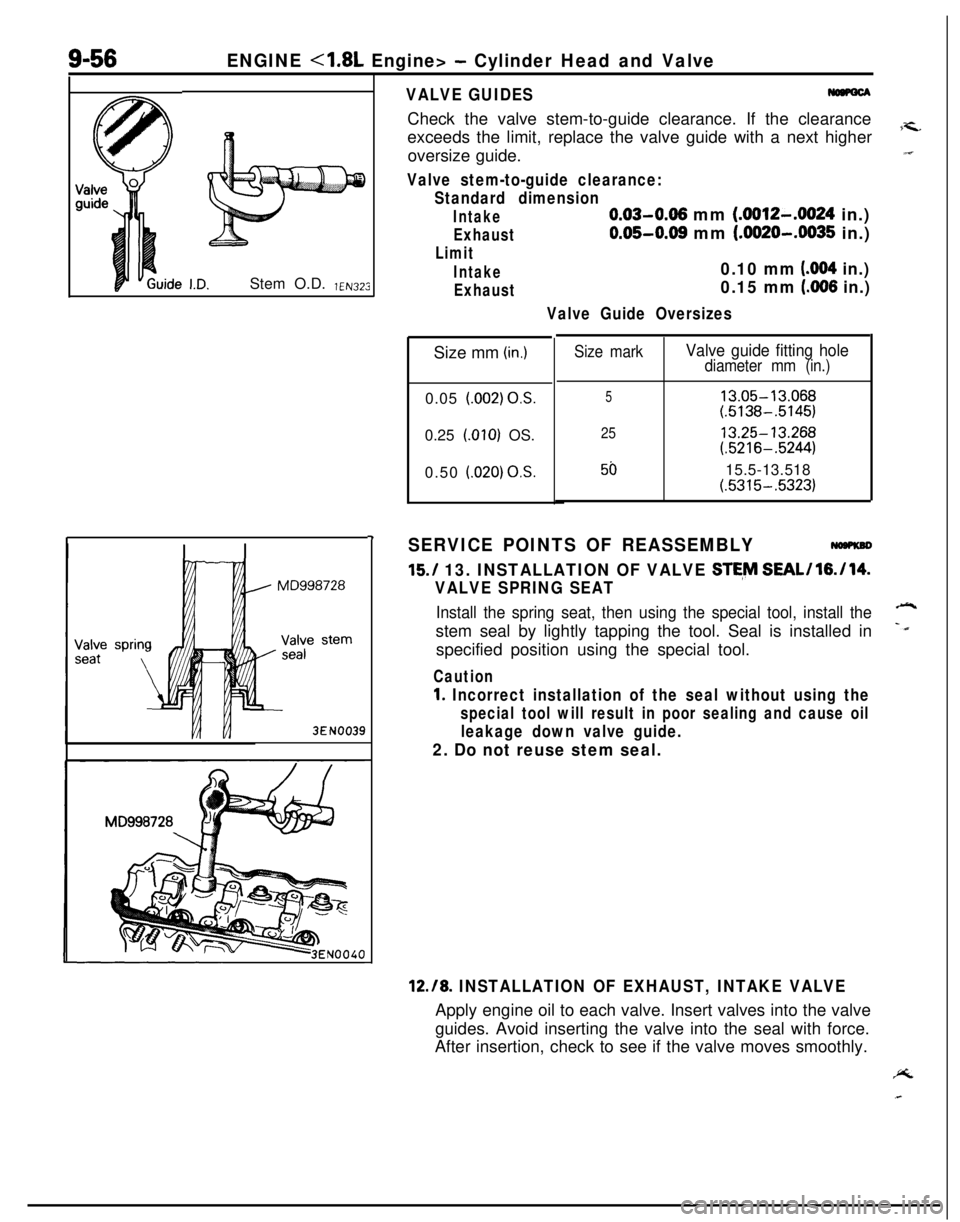
VALVE GUIDESCheck the valve stem-to-guide clearance. If the clearance
exceeds the limit, replace the valve guide with a next higher
7-c.oversize guide.“I
Valve stem-to-guide clearance:
Standard dimension
Intake0.03-0.06 mm (.0012-.0024 in.)
Exhaust0.05-0.08 mm (.0020-.0035 in.)
Limit
Intake0.10 mm (004 in.)
Exhaust0.15 mm (.006 in.)
Valve Guide OversizesSize mm
(in.)0.05
l.002) OS.0.25
LOlO) OS.
0.50
i.020) OS.
Size markValve guide fitting holediameter mm (in.)
513.05-13.068(.5138-.5145)
2513.25-13.268(.5216-.5244)
5015.5-13.518(.5315-.5323)
SERVICE POINTS OF REASSEMBLY
15./ 13. INSTALLATION OF VALVE STE,M SEAL/l6./14.
VALVE SPRING SEAT
Install the spring seat, then using the special tool, install the-stem seal by lightly tapping the tool. Seal is installed in
-dspecified position using the special tool.
Caution
1. Incorrect installation of the seal without using the
special tool will result in poor sealing and cause oil
leakage down valve guide.
2. Do not reuse stem seal.
12.18. INSTALLATION OF EXHAUST, INTAKE VALVEApply engine oil to each valve. Insert valves into the valve
guides. Avoid inserting the valve into the seal with force.
After insertion, check to see if the valve moves smoothly.PL
Page 341 of 1216
ENGINE <1.8L Engine> - Cylinder Head and Valve9-57
Enamel-
coating
sideSpring
retainerStem seal
Spring- seat
3EN324intake side
3EN315Front of engine
I,Exhaust side
11./7. INSTALLATION OF VALVE SPRINGInstall the valve spring with its enamel coated end toward
the valve spring retainer.
9.15. INSTALLATION OF RETAINER LOCK(1) Using the special tool, compress the spring, and then
install the retainer lock.
Caution
When compressing the spring, check to see that the
valve stem seal is not pressed to the bottom of the
retainer.
(2) Make certain that retainer locks are positively installed.
1. INSTALLATION OF CYLINDER HEAD BOLTSUsing the special tool, tighten in the order shown in two or
three steps, gradually tighten. Finally tighten to the speci-
fied torque.