Page 868 of 1216
21-174AUTOMATIC TRANSAXLE - Special Tools
NumberNameI Use
MD99891 5Wrench adapterUse the MD99891 8
MD99891 9Snap ring installerReassembly of endclutch
Page 869 of 1216

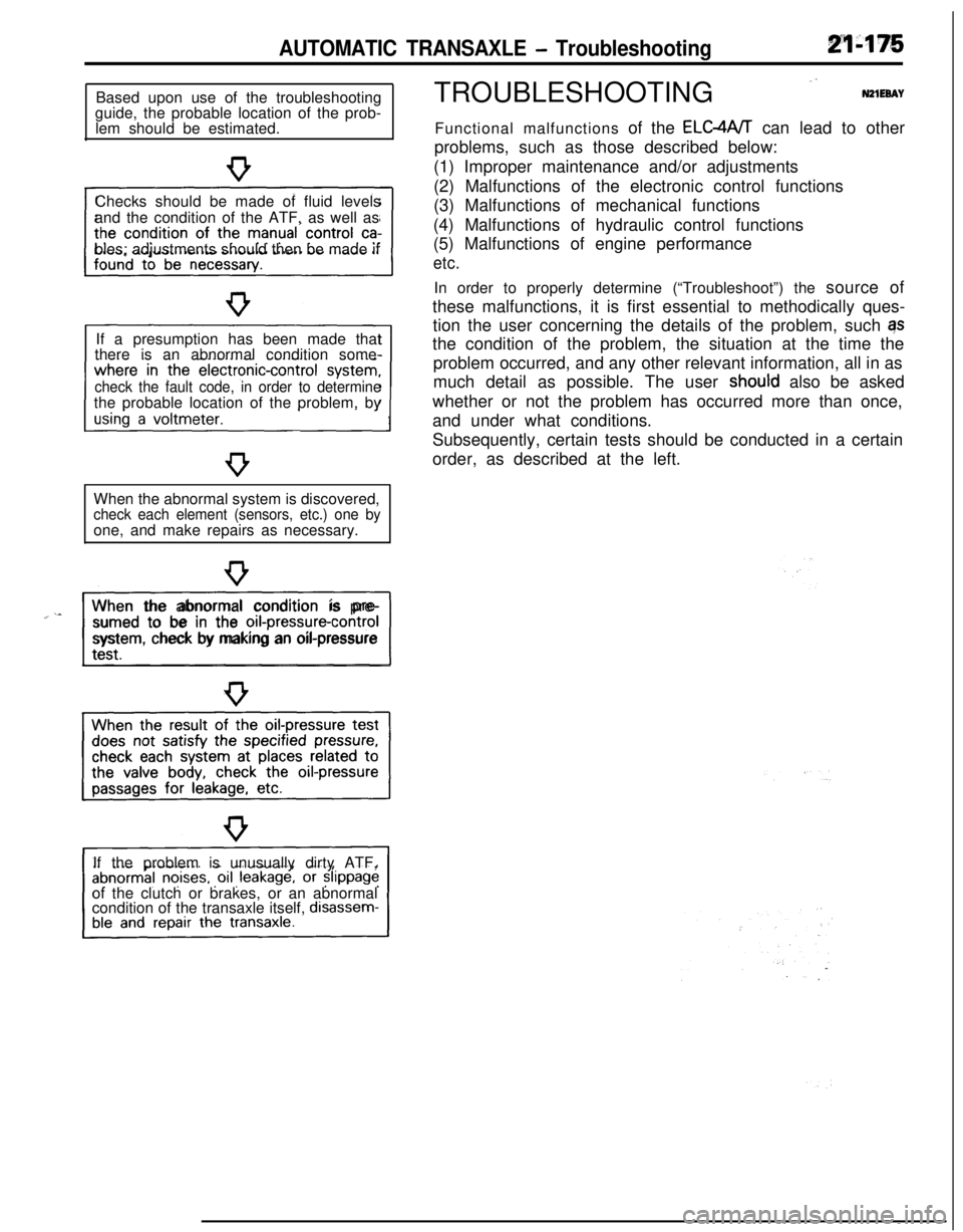
AUTOMATIC TRANSAXLE - TroubleshootingBased upon use of the troubleshooting
guide, the probable location of the prob-
lem should be estimated.
Checks should be made of fluid levels
and the condition of the ATF, as well as
bles; adjustments should then be made if
If a presumption has been made that
there is an abnormal condition some-
check the fault code, in order to determinethe probable location of the problem, by
When the abnormal system is discovered,
check each element (sensors, etc.) one byone, and make repairs as necessary.
“~^II_When the abnormal condition is pre-
sumed to be in the
orI-pressure-controlsystem, check by making an oil-pressure
If the problem is unusually dirty ATF,
of the clutch or brakes, or an abnormal
condition of the transaxle itself,
disassem-TROUBLESHOOTING
”N21EeAYFunctional malfunctions of the ELC4A/T can lead to other
problems, such as those described below:
(1) Improper maintenance and/or adjustments
(2) Malfunctions of the electronic control functions
(3) Malfunctions of mechanical functions
(4) Malfunctions of hydraulic control functions
(5) Malfunctions of engine performance
etc.In order to properly determine (“Troubleshoot”) the source of
these malfunctions, it is first essential to methodically ques-
tion the user concerning the details of the problem, such qs
the condition of the problem, the situation at the time the
problem occurred, and any other relevant information, all in as
much detail as possible. The user
shoutd also be asked
whether or not the problem has occurred more than once,
and under what conditions.
Subsequently, certain tests should be conducted in a certain
order, as described at the left.
Page 871 of 1216
AUTOMATIC TRANSAXLE - Troubleshooting
-
T13456
-
7
s
s
roii
i?-
13
14
ii-
16
n
Is-
19-!O-
!l-!2-
!3-
!4-!5-
!6
c
!6-!9
,o
n
i-
i?
r
ii-
k-ii
ir
lise, otherTransaxle malfunction of shift-s Transaxle malfunction of shift-sg
-0992
pla8g.E!Pp
.G c55.-,fi$
0%8-
-
-
-
-
-
-
-
-
-
-
-
-X
-
-
-
-
-
-
-
-
s---
-X
-
-
-
-
-
-
-
-
-
-
-
-
-X-X
-
X-XX
-
x-
-
-
-
-
-
-
-X-
PSCV =Pressure control solenoid valve
DCCSV = Damper clutch control solenoid valve
i
Page 872 of 1216

21-178AUTOMATIC TRANSAXLE - Troubleshooting
09P0010Fluid level must be
within this range.09PoOll
0”
Two302
DIAGNOSIS AND TEST
FLUID LEVEL AND CONDITION1. Drive until the fluid temperature reaches the usual tem-
perature
[70-80°C (160- 18O”F)I.2. Place vehicle on level floor.
3. Move selector lever sequentially to every position to fill
torque converter and hydraulic circuit with fluid, then place
lever in “N” Neutral position. This operation is necessary tobe sure that fluid level check is accurate.
4. Before removing dipstick, wipe all dirt from area around
dipstick. Then take out the dipstick and check the conditionof the fluid.
The transaxle should be overhauled under the following
conditions.l If there is a “burning” odor.
l If the fluid color has become noticeably blacker.
lIf there is a noticeably great amount of metal particles inthe fluid.
5.Check to see if fluid level is in “HOT” range on dipstick. If
fluid level is low, add automatic transaxle fluid until level
reaches “HOT” range.
Low fluid level can cause a variety of conditions because itallows pump to take in air along with fluid. Air trapped in
hydraulic circuit forms bubbles which make fluid spongy.
Therefore, pressures will be erratic.
Improper filling can also raise fluid level too high. When
transaxle has too much fluid, gears churn up foam and
cause same conditions which occur with low fluid level,
resulting in accelerated deterioration of automatic transaxle
fluid.In either case, air bubbles can cause overheating, fluid
oxidation, which can interfere with normal valve, clutch,
and servo operation. Foaming can also result in fluid
escaping from transaxle vent where it may be mistaken for
a leak.
6. Be sure to examine fluid on dipstick closely.
CONTROL CABLE
Whether control cable is properly adjusted can be confirmed bychecking whether inhibitor switch is performing well.
1. Apply parking brakes and service brakes securely.
2. Place selector lever to “R” range.
3. Set ignition key to “ST” position.
4. Slowly move the selector lever upward until it clicks as it
fits in notch of “P” range. If starter motor operates when
lever makes a click, “P” position is correct.
5.Then slowly move selector lever to “N” range by the same
procedure as in foregoing paragraph. If starter motor
operates when selector lever fits in “N”, “N” position is
correct.6. Also check to be sure the vehicle doesn’t begin to move
and the lever doesn’t stop between P-R-N-D.
7. The control cable is properly adjusted if, as described
above, the starter motor starts at both the “P” range and
the “N” range.
Page 875 of 1216

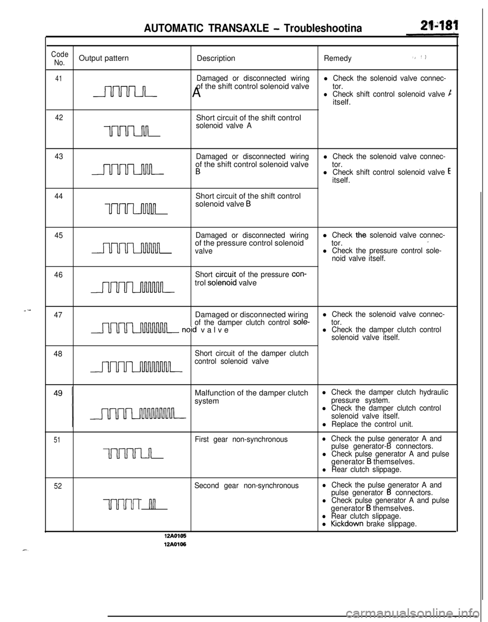
AUTOMATIC TRANSAXLE - Troubleshootina
Code.> ‘)No.Output pattern
DescriptionRemedy
41Damaged or disconnected wiringl Check the solenoid valve connec-of the shift control solenoid valve
nnnn A
tor.lCheck shift control solenoid valve Citself.
42Short circuit of the shift control
uuu-mn
solenoid valve A
43Damaged or disconnected wiring
l Check the solenoid valve connec-of the shift control solenoid valve
- B
tor.l Check shift control solenoid valve Eitself.
44Short circuit of the shift control
uuvuwlnsolenoid valve B
45Damaged or disconnected wiringlCheck the, solenoid valve connec-,.
uuuumnof the pressure control solenoidtor.valvel Check the pressure control sole-
noid valve itself.
46
J-~-,,-=
Short circu.it of the pressure con-trol
solenoid valve
47Damaged or disconnected wiringl Check the solenoid valve connec-
of the damper clutch control
sole-nnnn~ noid valvetor.l Check the damper clutch control
solenoid valve itself.48
Short circuit of the damper clutchnnnncontrol solenoid valveMalfunction of the damper clutch
l Check the damper clutch hydraulicsystem
pressure system.l Check the damper clutch control
solenoid valve itself.
l Replace the control unit.
51First gear non-synchronouslCheck the pulse generator A and
UUUUI~
pulse generator-B connectors.l Check pulse generator A and pulsegenerator B themselves.l Rear clutch slippage.
52Second gear non-synchronouslCheck the pulse generator A and
pulse generator B connectors.
uuuul nnlCheck pulse generator A and pulsegenerator
B themselves.l Rear clutch slippage.l Kickdown brake slippage.
I-Y I”*
12Ao106
Page 876 of 1216

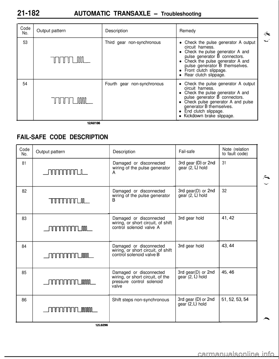
21-182AUTOMATIC TRANSAXLE - TroubleshootingDescription
Code
No.
53Output pattern
UUUULnnn-
Remedy
lCheck the pulse generator A output
circuit harness.
lCheck the pulse generator A and
pulse generator
B connectors.
lCheck the pulse generator A andpulse generator B themselves.
l Front clutch slippage.l Rear clutch slippage.
lCheck the pulse generator A output
circuit harness.
lCheck the pulse generator A and
pulse generator B connectors.
l Check pulse generator A and pulsegenerator
B themselves.
l End clutch slippage.
l Kickdown brake slippage. Third gear non-synchronous
54Fourth gear non-synchronous
uuuuLnMn-12A0106
FAIL-SAFE CODE DESCRIPTION
CodeNo.Output patternDescriptionFail-safeNote (relation
to fault code)
81Damaged or disconnectedwiring of the pulse generator
A3rd gear (D) or 2nd
gear (2, L) hold
31
3rd gear(D) or 2ndgear (2, L) hold
32Damaged or disconnectedwiring of the pulse generator
B
82
83
3rd gear hold41,42Damaged or disconnectedwiring, or short circuit, of shift
control solenoid valve A43,44
843rd gear hold
Damaged or disconnectedwiring, or short circuit, of shift
control solenoid valve
B
Damaged or disconnectedwiring, or short circuit, of the
pressure control solenoid
valve
45,463rd gear(D) or 2ndgear (2, L) hold85
86Shift steps non-synchronous3rd gear (D) or 2nd
gear (2, L) hold51,52,53,54
12LO296
Page 877 of 1216

AUTOMATIC TRANSAXLE - Troubleshooting214%3
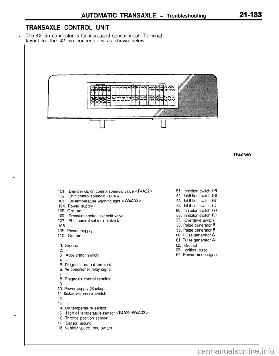
TRANSAXLE CONTROL UNIT
-‘” .The 42 pin connector is for increased sensor input. Terminal
layout for the 42 pin connector is as shown below.TFA0360
101.Damper clutch control solenoid valve
102.Shift control solenoid valve A
103.Oil temperature warning light 104. Power supply
105. Ground
106.Pressure control solenoid valve
107.Shift control solenoid valve B108.
-
109. Power supply
110. Ground
1. GroundL.
-
3.Accelerator switch
4.-5. Diagnosis output terminal
6. Air conditioner relay signal
7.-8. Diagnosis control terminal
9.-
IO. Power supply (Backup)
11. Kickdown servo switch
12.-
13.-14. Oil temperature sensor
15.High oil temperature sensor
16. Throttle position sensor
17.Sensor ground18. Vehicle speed reed switch
51. Inhibitor switch (PI52. Inhibitor switch
(8)53. Inhibitor switch
(N)54. Inhibitor switch
(D)
55. Inhibitor switch (2)56. inhibitor switch
(L)
57.Overdrive switch
58. Pulse generator
B59. Pulse generator
B60. Pulse generator A
61. Pulse generator A
62.Ground63.Ignition pulse64. Power mode signal
Page 878 of 1216

21-184AUTOMATIC TRANSAXLE - TroubleshootinaSelector
lever
position
P
R
N
ELEMENT IN USE AT EACH POSITION OF SELECTOR LEVER
2
LCl
Front clutch
C2 Rear clutch
C3 End clutch
Bl Kickdown brakeSHIFT PAlTERNS82 Low-reverse brake
OWC Oneway clutchTwo shift patterns are pre-stored in the control unit of this
transaxle. One is the power pattern (for more powerful
performance), and the other is the economy pattern (for
improved fuel consumption and quieter operation).
The driver can select and switch to the desired pattern by usingthe power/economy select switch on the center console.
The solid lines shown in these shift patterns indicate up-shifts,
and the broken lines indicate down-shifts. The reason why
there is a difference between the shift points for up-shifts and
for down-shifts is so that up-shifts and down-shifts will not
occur frequently when driving at a speed in the vicinity of the
shift point.
When the vehicle is stopped, there is a shift to
2nd gear in
order to obtain a suitable “creeping”, but when the accelerator
pedal is then depressed the vehicle starts off in
1st gear.