Page 903 of 1216

AUTOMATIC TRANSAXLE - service Adjustment Procedures21-209
09Pooi awith this range.
09POOll
TWO382
SERVICE ADJUSTMENT PROCEDURESN21FB6E
TRANSAXLE FLUID LEVEL INSPECTION1. Drive until the fluid temperature reaches the usual tem-
perature
[70-80°C (160- 18O”F)I.2. Place vehicle on level floor.
3. Move selector lever sequentially to every position to fill
torque converter and hydraulic circuit with fluid, then place
lever in “N” Neutral position.
4. Before removing dipstick, wipe all dirt from area around
dipstick. Then take out the dipstick and check the conditionof the fluid.
The transaxle should be overhauled under the following
conditions.l If there is a “burning” odor.
l If the fluid color has become noticeably blacker.
lIf there is a noticeably great amount of metal particles inthe fluid.
5.Check to see if fluid level is in “HOT” range on dipstick. If
fluid level is low, add automatic transaxle fluid until level
reaches “HOT” range.
Transaxle fluid: MOPAR ATF PLUS (Automatic trans-
mission fluid type 7176) or Dia ATF SPor equivalent
Low fluid level can cause a variety of conditions
becaljse it
allows pump to take in air along with fluid. Air trapped in
hydraulic circuit forms bubbles which make fluid spongy.
Therefore, pressures will be erratic, causing delayed shift,
slippy clutch and brakes, etc.
Improper filling can also raise fluid level too high. When
transaxle has too much fluid, gears churn up foam and
cause the same conditions which occur with low fluid level,
resulting in accelerated deterioration of automatic transaxle
fluid.In either case, air bubbles can cause overheating, fluid
oxidation, which can interfere with normal valve, clutch,
and servo operation.Foaming can also result in fluid
escaping from transaxle vent where it may be mistaken for
a leak.6. Be sure to examine fluid on dipstick closely.
TRANSAXLE FLUID REPLACEMENTN21FCBAaRefer to GROUP O-Maintenance Service.
TRANSFER OIL LEVEL INSPECTIONNZlFXAATransfer oil level inspection is the same as for the manual
transaxle transfer.
Refer to GROUP
22-Service Adjustment Procedures.
TRANSFER OIL REPLACEMENTNZlFYAFaTransfer oil replacement is the same as for manual transaxle
transfer.Refer to GROUP
22-Service Adjustment Procedures.
Page 922 of 1216
21-228AUTOMATIC TRANSAXLE - Transaxle Assembly
DISASSEMBLY AND REASSEMBLY NZlLEBB
\18
1720
\231. Torque converter
2. Converter housing
3. Gasket
4. Oil
pump5. O-ring
6. Gasket
7. Thrust washer
#l
8.Front clutch assembly9. Thrust race #3
10. Thrust bearing #411.Thrust washer #212.Rear clutch assembly13.Spacer14.Differential
15.Thrust bearing #616.Clutch hub
17. Thrust race #7
18. Thrust bearing #819.Kickdown band20.Kickdown drum21.Snap ring
22.Center support23.O-ring
24.Wave spring25.Return spring26.Pressure plate27.Brake disc
28.Brake plate29.Reaction plate
30. Reverse sun gear31. Thrust bearing #932.Thrust race # 10
33. Forward sun gear
34.Planetary carrier35.Thrust bearing #12
Page 923 of 1216

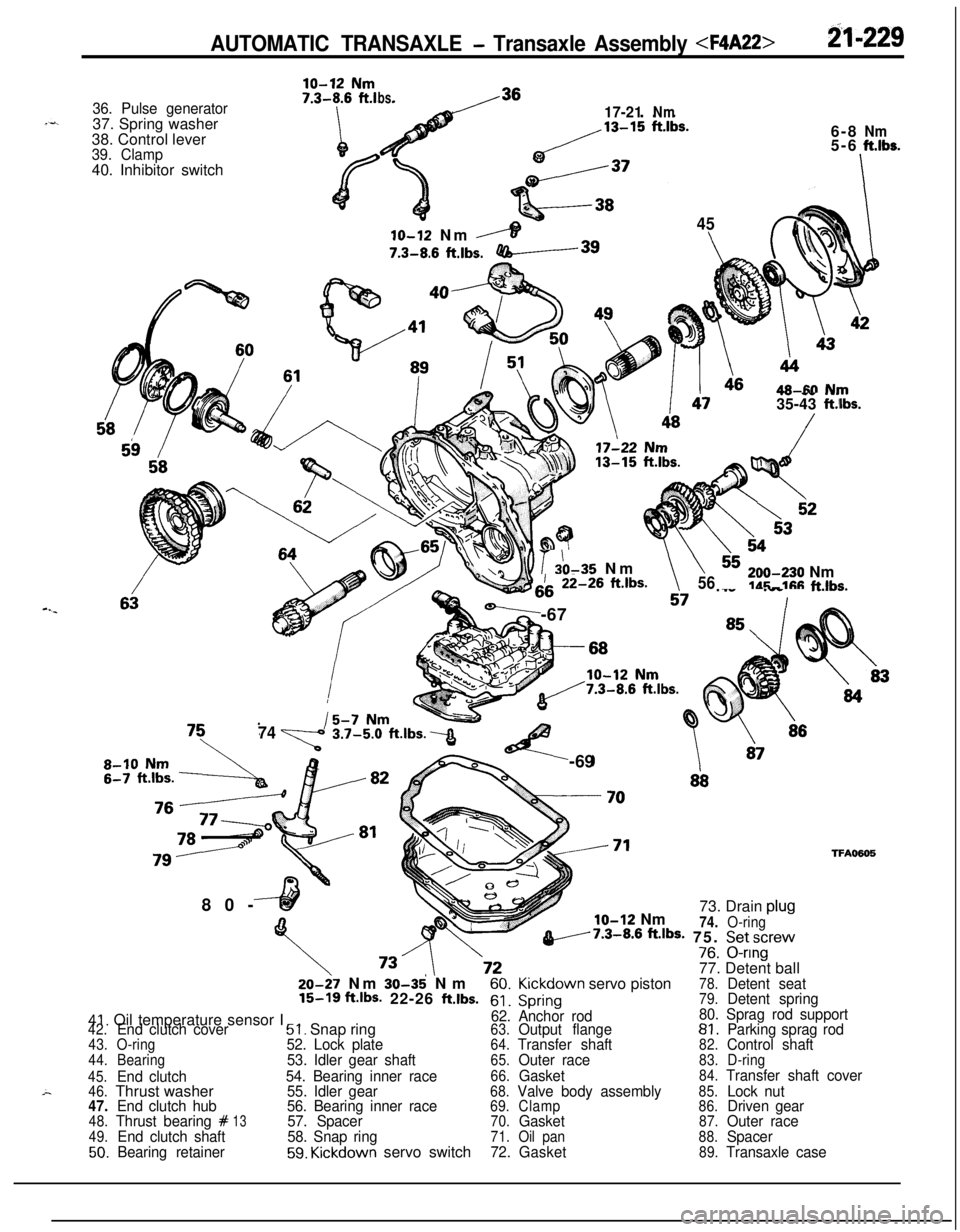
AUTOMATIC TRANSAXLE - Transaxle Assembly B-229
36. Pulse generator37. Spring washer
38. Control lever
39. Clamp40. Inhibitor switch
ln ~19 Nm
bs.17-21Nm6-8
Nm5-6ft.lbs.
-I
45
6IO-12 Nm
,----IT7.3-8.6
ftlbs.-3980-
46AR-M N~JTV -- .-.35-43 ft.iIbs.
b??io r 20-35 Nm\h\\iii-26 ft.lbs.
-,i7 ._.. .__ ._..v.-6756,,,-e30 Nmldr;-11% f-klhs.
I
,
747%!%t.lbs.3<-69
glo-12 Nm73. Drain plu!
74.O-ringv7.3-8.6 ftJbS- 75. Setscrev-^^V/8. u-nng
77. Detent ball
TFA050520-27 Nm
30-35' Nm60.Kickdown servo piston78.Detent seat15-16 ft.lbs- 22-26 ftlbs.61.Spring79.Detent spring
41. Oil temperature sensor I62. Anchor rod80. Sprag rod support42.End clutch cover51. Snap ring63.Output flange81.Parking sprag rod43.O-ring52. Lock plate64.Transfer shaft82.Control shaft44.Bearing53. Idler gear shaft65.Outer race83.D-ring
45.
End clutch54. Bearing inner race66.Gasket84.Transfer shaft cover
46.Thrust washer55. Idler gear68.Valve body assembly85.Lock nut47.End clutch hub56. Bearing inner race69.Clamp86.Driven gear48.Thrust bearing #1357. Spacer70.Gasket87.Outer race49.End clutch shaft58. Snap ring71.Oil pan88.Spacer50.Bearing retainer59. Kickdown servo switch72.Gasket89.Transaxle case
Page 924 of 1216

-2.rt-2-30~~ AUTOMATIC TRANSAXLE - Transaxle Assembly
;haft1770083
DISASSEMBLYNZlLEAl1. Clean away any sand, mud, etc. adhered around the
.+
transaxle..
2.
Place the transaxle assembly on the workbench with the oil--’
pan down.
3. Remove the torque converter.
4. Measuring input shaft end play before disassembly will
usually indicate when a thrust washer change is required
(except when major parts are replaced). Thrust washers arelocated between reaction shaft support and rear clutch
retainer, and between reaction shaft support and front
clutch retainer.
Mount a dial indicator to converter housing with the Dial
Indicator Support. Make sure that the indicator plunger is
seated against end of input shaft.
When checking end play, pull out or push in the input shaft
with pliers. Be careful not to scratch the input shaft. Record
indicator reading for reference when reassembling transax-
le.5. Remove the pulse generator “A” and “B”
6. Remove manual control lever, then remove inhibitor
switch.
7. Remove snap ring then remove
kickdown servo switch.
Page 925 of 1216
AUTOMATIC TRANSAXLE - Transaxle Assembly 21-237
sensor17504288. Remove the oil pan and gasket.
9. Remove the oil filter from the valve body.
10. Remove the oil-temperature sensor installation bolt; then,
after removal from the bracket, pull out from the connector
side.11. Insert the solenoid valve harness grommet and connector
into the transaxle case.
12. Remove 10 bolts and remove valve body.
13. Remove the end clutch cover mounting bolt the cover
holder, and the end clutch cover.
Page 926 of 1216
21-232AUTOMATIC TRANSAXLE - Transaxle Assembly 14. Remove the end clutch assembly.
15. Remove the thrust plate.
16. Remove the end clutch hub and thrust bearing.
17. Pull out the end clutch shaft.
18. Remove 13 bolts and remove converter housing.
Page 927 of 1216
AUTOMATIC TRANSAXLE - Transaxle Assembly 21-233
19. Remove 6 bolts, and attach the special tools and remove oilpump assembly.
20. Remove the spacer and the differential assembly.
21. Remove the thrust washer
#I22. Pull up the input shaft, and then remove the front clutch
assembly and the rear clutch assembly together.
23. Remove the thrust bearing
#6.
Page 928 of 1216
21-234AUTOMATIC TRANSAXLE - Transaxle Assembly 24. Remove the clutch hub.
25. Remove the thrust race
#7 and bearing #8.26. Remove the kickdown drum.
27. Remove the kickdown band.
28. Using the valve spring compressor and special tool, push inthe kickdown servo and remove the
.snap ring.