Page 713 of 1216

MANUAL TRANSAXLE - Transaxle21-19
TRANSAXLE
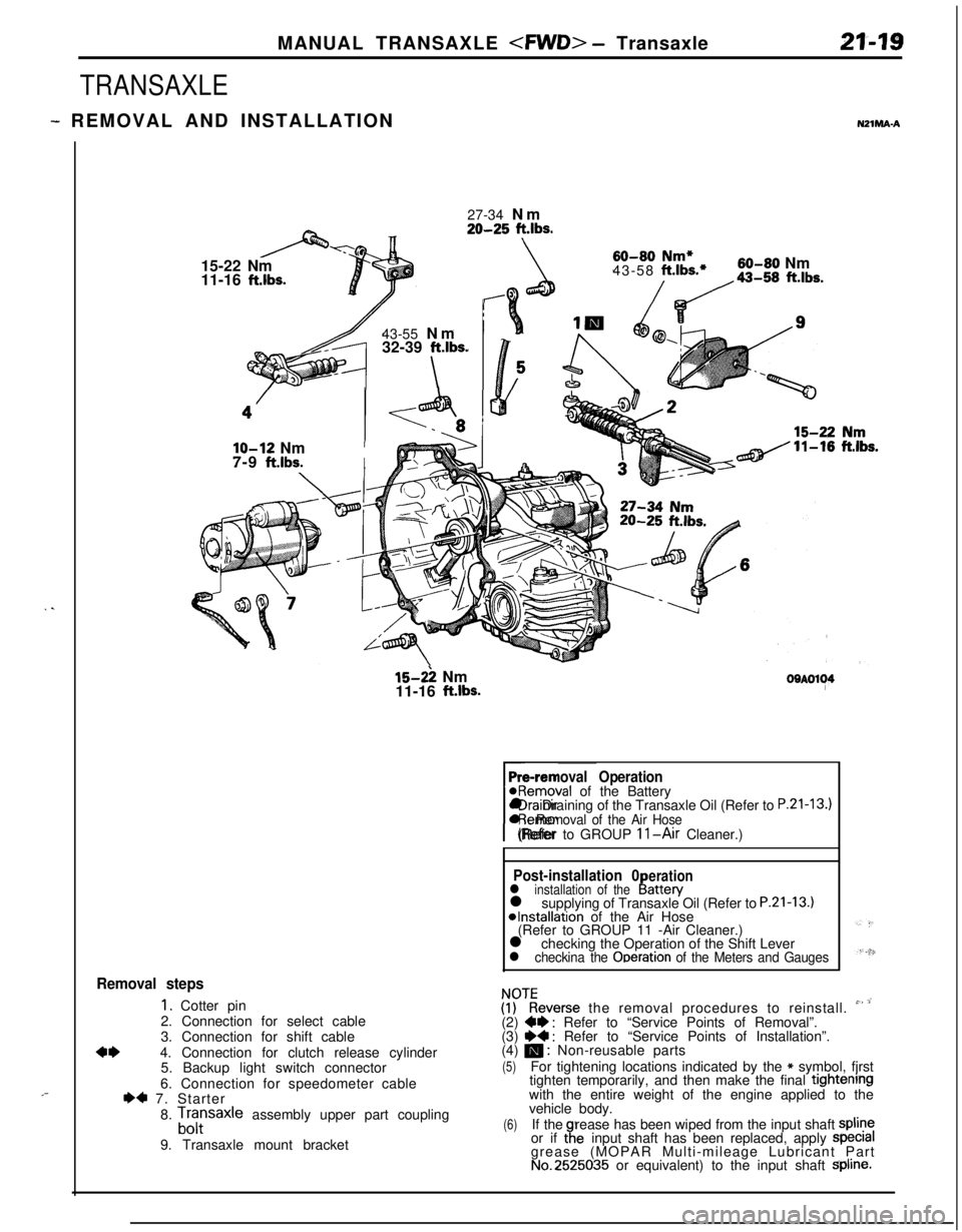
- REMOVAL AND INSTALLATIONNZlMA-A
. .
,-27-34 Nm
20-25 ft.lbs.15-22 Nm
11-16
ft.lbs.43-55 Nm
32-39
ft.lbs.
\
60-80 Nm*43-58 ft.lbs.*60-80 Nm
/da-,, ft.lbs.
lo-12 NmI7-9
ft.lbs.I
15-2: Nm
11-16 ft.lbs.OOAOl~4
Pre-removal Operation@Removal of the Battery
rl Draining of the Transaxle Oil (Refer to
P.21-13.)l Removal of the Air Hose(Refer to GROUP 11-Air Cleaner.)
Post-installation 0erationl installation of theI!attery
l supplying of Transaxle Oil (Refer to P.21-13.)*Installation of the Air Hose
(Refer to GROUP 11 -Air Cleaner.)
l checking the Operation of the Shift Lever
l checkina the Ooeration of the Meters and Gauges
Removal steps
1. Cotter pin
2. Connection for select cable
3. Connection for shift cable
4*4. Connection for clutch release cylinder
5. Backup light switch connector
6. Connection for speedometer cable
I)* 7. Starter
8.
Lfrsaxle assembly upper part coupling
9. Transaxle mount bracket
ZKeverse the removal procedures to reinstall. ” ’(2) W : Refer to “Service Points of Removal”.
(3) ~~ : Refer to “Service Points of Installation”.
(4) m : Non-reusable parts
(5)For tightening locations indicated by the * symbol, fjrst
tighten temporarily, and then make the final tightenrngwith the entire weight of the engine applied to the
vehicle body.
(6)If therease has been wiped from the input shaft spline
or if taeinput shaft has been replaced, apply specralgrease (MOPAR Multi-mileage Lubricant Part
No.2525035 or equivalent) to the input shaft Spline.
Page 717 of 1216
MANUAL TRANSAXLE - Transaxle Assemblv 2743
TRANSAXLE ASSEMBLY
.._DISASSEMBLY AND REASSEMBLYN21ME-A
__
30-42 Nm22-30 ft.lbs.30-35 Nm22-25 ftlbs.q l4
ig5 !
----7m
IQ15-22 Nm
II-15 ft.lbs.
4.0-5.5 Nm2.9-3.9 ft.lbs.1I”I
a
140-160 Nmf
102-115 ft.lbs.
Disassembly steps
1. Bolt
l + 2. Rear cover
3. Wave spring
l 4. Screw bolts
5. Reverse brake cone
6. Backup light switch
7. Gasket
8. Poppet plug
9. Poppet spring
10. Poppet ball
11. Bolt
12. Speedometer driven gear assembly
l * 13. Air breather
*I) l * 14. Spring pin+I) l * 15. Lock nut
140-160102-115
TFMOOl6
+e I)+ 16. Lock nut
17. 5th speed synchronizer assembly
18. 5th speed shift fork
19. Synchronizer ring
20. 5th speed gear
21.Needle
bearing
22. 5th speed intermediate gear
NOTE(1) Reverse the disassembly procedures to reasseinble.
(2) ++ : Refer to “Service Points of Disassembly”.(3) l * : Refer to “Service Points of ReaSsembly”:(4) m : Non-reusable parts
Page 721 of 1216
MANUAL TRANSAXLE - Transaxle Assemblv 21-27
206001E
47./48. REMOVAL OF SHIFT RAILS AND FORKS’(1) Shift the Ist-2nd speed shift fork to the
2nd speed.
(2) Shift the
3rd~4th speed shift fork to the 4th speed.
(3)Rotate the the shift controls in the direction of the arrowin numerical order. Remove the shift lugs from the
control finger and interlock plate.
(4) Raise each of the shift rails upward and remove them
from the clutch housing.
(5) Remove the all shift rails and forks.
52. REMOVAL OF INTERMEDIATE GEAR ASSEMBLYLift up the input shaft assembly and remove the intermedi-
ate gear assembly.
INSPECTION
BACKUP LIGHT SWITCH
N21MOdOperate the backup light switch to check continuity with a
circuit tester. If without continuity, replace the switch.
SERVICE POINTS OF REASSEMBLYN2mnGAU
61. INSTALLATION OF OIL SEALInstall the drive shaft oil seal using the special tool.
Page 727 of 1216
MANUAL TRANSAXLE - Transaxle Assembly n-33
TRANSAXLE ASSEMBLY
3 DISASSEMBLY AND REASSEMBLYNZlME-6
--42 Nm
-30
ft.lbs.
\8I Q
30-35Nm
22-25ft.lbs.ml4
ff3d6 i
18
4.0-5.5Nm2.9-3.9ft.lbs.
-n
140-160 Nm102-115ft.&s.
3-5 Nm
16-22 Nm11-15 ft.lbs.1Disassembly steps
‘I. Bolt
l *2. Rear cover3.Wave springe4 4. Screw bolts5. Reverse brake cone6. Backup light switch
7.Gasket
8.Poppet plug9.Poppert spring
10.Poppet ball11.Bolt
12. Speedometer driven gear assembly
l 13. Air breather
4* l * 14. Spring pin
,I
2
TFMool6
4+ e4 15. Lock nut+e l 16. Lock nut17. 5th speed synchronizer assembly18. 5th speed shift fork19. Synchronizer ring20. 5th speed gear21. Needle bearing22.
5th speed intermediate gear.’
$?everse the disassembly procedures to reassemble.(2) +e : Refer to “Service Points of Disassembly:.(3) l C : Refer to “Service Points of Reassembly(4) q : Non-reusable parts
Page 731 of 1216
MANUAL TRANSAXLE - Transaxle Assemblv 21-37
18
50. REMOVAL OF SHIFT RAIL ASSEMBLY(1) Shift the
1st~2nd speed shift fork to the 2nd speed.
(2) Shift the
3rd4th speed shift fork to the 4th speed.
.”(3) Remove the shift rail assembly.
INSPECTIONNZlMOM
BACKUP LIGHT SWITCHOperate the backup light switch to check continuity with a
circuit tester.
If without continuity, replace the switch.
SERVICE POINTS OF REASSEMBLY64. INSTALLATION OF OIL SEAL
Install the drive shaft oil seal using the special tool.
:
Page 769 of 1216

MANUAL TRANSAXLE - Specifications21-75Items
Lower arm ball joint to knuckle
Center bearing bracket installation bolts
Right member installation bolt (front)
Right member installation bolt (rear)
Transfer assembly mounting bolt
Poppet plug
Backup light switch
Restrict ball
Speedometer mounting bolt
Oil filler plug
Oil drain plug
Input shaft lock nut
Intermediate shaft lock nut
Center differential drive gear mounting bolt
Front differential drive gear mounting bolt
Stopper bracket mounting bolt
Reverse idler gear shaft mounting bolt
Reverse shift lever mounting bolt
Bearing retainer mounting bolt
Interlock plate mounting bolt
Center member mounting bolt
Irive shaft center bearing mounting bolt
Iriven bevel lock nutgear
Select lever assembly mounting bolt
3everse brake cone screw boltsNm
ft.Ibs. ”
60-7243-52 “
36-4626-33
80-10058-72
70-8051-58
55-6040-43
30-4222-30
30-3522-25
30-3522-25
3-52.5-3.5
30-3522-25
30-3522-25
140-160102-I 15
140-160102-I 15
70-8051-57
130-14095-10115-22
11-1543-55
32-39
15-22
11-1515-22
11-15
20-2715-19
60-8043-58
36-46
26-33
140-160101-11515-22
11-15
4.0-5.52.9-3.9
TRANSFERItems
Transfer assembly mounting bolt
Cover mounting bolt
Extension housing mounting bolt
Transfer cover mounting bolt
Transfer case adapter mounting bolt
Driven bevel gear lock nut
Hanger bracket mounting boltNm
ft.lbs.
55-6040-43
8-106-7
15-22
II-1535-42
26-3035-42
26-30
140-160102-I 15
15-22
11-15
LUBRICANTSN21CD.BItems
Specified lubricantQuantity lit. (qts.)
I
ITransmission oil
MOPAR Hypoid gear oil or equivalent,2.3 (2.43)
API classification GL-4 or higherITransfer oil
MOPAR Hypoid gear oil or equivalent,
API classification
GL-4 or higher0.6 (.63)
Page 776 of 1216

21-82MANUAL TRANSAXLE - Transaxle
TRANSAXLE
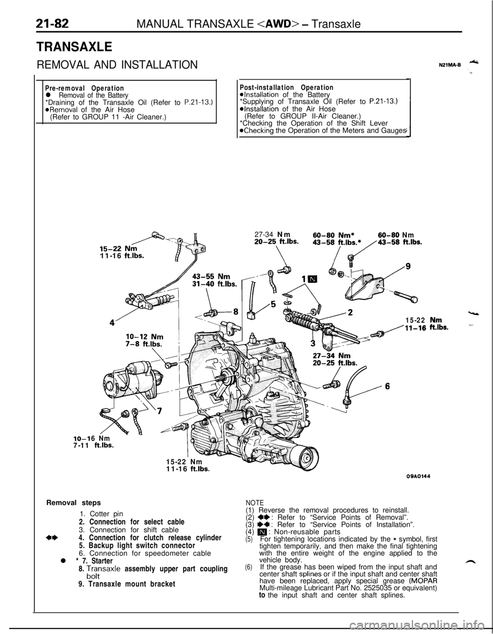
REMOVAL AND INSTALLATION
Pre-removal Operationl Removal of the Battery*Draining of the Transaxle Oil (Refer to P.Zl-13.)
@Removal of the Air Hose
(Refer to GROUP 11 -Air Cleaner.)IO-1
7-1111-16
ftlbs.
Post-installation Operation@Installation of the Battery
*Supplying of Transaxle Oil (Refer to P.21-13.)*Installation of the Air Hose
(Refer to GROUP II-Air Cleaner.)
*Checking the Operation of the Shift Lever
@Checking the Operation of the Meters and Gauges
27-34 Nm
60-60 Nm*60-80 Nm20-25 ft.lbs.
\
43-58/t.,b~43-58 ft.lbs.
15-22
6 Nm
ftlbs.
15-22 Nm
vt11-16
ft.lbs.Removal steps
1. Cotter pin
2. Connection for select cable
3. Connection for shift cable
*I)4. Connection for clutch release cylinder
5. Backup light switch connector
6. Connection for speedometer cable
l * 7. Starter
8.
A;;saxle assembly upper part coupling
9. Transaxle mount bracket
NZlMA-B -
,“rr,s.
09AOl44
NOTE(1) Reverse the removal procedures to reinstall.
(2)
+e : Refer to “Service Points of Removal”.
(3) I)+ : Refer to “Service Points of Installation”.
(4) m : Non-reusable parts(5)For tightening locations indicated by the * symbol, first
tighten temporarily, and then make the final tightening
with the entire weight of the engine applied to the
(6)vehicle body.
If the grease has been wiped from the input shaft and
center shaft splines or if the input shaft and center shaft
have been replaced, apply special grease
(MOPARMulti-mileage Lubricant Part No. 2525035 or equivalent)
to the input shaft and center shaft splines.
Page 778 of 1216

21-84MANUAL TRANSAXLE - Transaxle
r) ’TransaxlellKfil1
SERVICE POINTS OF REMOVALN21MBAV4. DISCONNECTION OF CLUTCH RELEASE CYLINDER/
12. TIE ROD
END/l4. LOWER ARM BALL JOINT
Refer to
P.21-21.15. DISCONNECTION OF DRIVE SHAFT
Insert a pry bar between the transaxle case and the drive
shaft, and then pry the drive shaft from the transaxle.
Caution
1.Do not pull on the drive shaft; doing so will damage
the inboard joint; be sure to use the pry bar.
2.Do not insert the pry bar so deep as to damaged theoil seal.
(1) Take out the drive shaft by lightly tapping the drive shaftT.J. case with a plastic hammer.
NOTERemove the drive shaft with the hub and knuckle, etc.,
as an assembly.
Caution
1. Removing the drive shaft from the,, outboa,rd
joint side can cause damage to the inboard joint.Always use a plastic hammer, etc., to remove
the drive shaft.
2. Tapping on the center bearing can damage it.
Never tap on the bearing.
(2) Keep the removed drive shaft as far away from the
transaxle case as possible, and secure (by using rope,
etc.) the joints to the body so that it does not fall.
17. REMOVAL OF FRONT EXHAUST PIPE
Refer to GROUP
1 l-Exhaust Pipe and Main Muffler.
18. REMOVAL OF TRANSFER ASSEMBLY
Refer to
P.21-85.23. REMOVAL OF TRANSAXLE ASSEMBLY
Refer to
P.21-22.
SERVICE POINTS OF INSTALLATION!’23. REMOVAL OF TRANSAXLE ASSEMBLY
Refer to
P.21-22.15. INSTALLATION OF DRIVE SHAFT
Refer to
P.21-22.7. INSTALLATION OF STARTER
Refer to
P.21-22.
NZlMDAQ