Page 780 of 1216
21-86MANUAL TRANSAXLE - Transaxle AssemblyTRANSAXLE ASSEMBLY
DISASSEMBLY AND REASSEMBLY
30-35 Nm
22-25 ft.lbs.
\
30-35 Nm
22-25 Wbs.
4.0-5.5 Nm\62.9-3.9 ft.lbs.7-42 Nm
-30
ft.lbs.llI8-59
I21IDisassembly steps
l + 1. Rear cover
2. Wave spring
I)+ 3. Screw bolts
4. Reverse brake cone
;. E;zk;p light switch
7: Restrict ball assembly
8. Gasket
9. Poppet plug
.- ^1 U. Poppet spring11. Poppet ball
I 2. Speedometer driven gear assembly
l + 13. Air breather
l * l 4 14.Spring pin
140-160 Nm
w ”Y
102-115 ft.lbs.
16Bl/
22
++ I)+ 15. Lock nut+el 416.Lock nut
l + 17. 5th speed synchronizer assembly~~ 18. Shift fork
19.Synchronizer ring
20.
5th speed gear
21.Needle bearing
22.
5th speed intermediate gear35-42 Nm
26-30 ft.lbs.-1
TFMOOZSNOTE
(1) Revers_e the di?: ’(2) +-(3) +v : neler 10(4) IW : Non-reusat-yle parts.assembly
proceaures 10 reassemble.ry : KeTer to Service Points of Disassembly”.“-I-- I- “Service Points of Reassembly”.
’
i
Page 793 of 1216
MANUAL TRANSAXLE - Transaxle Assembly/Backup Light Switch21-99
sealant
TFM0041
TFM003513. INSTALLATION OF AIR BREATHER
Apply sealant to the areas with which the air breather
makes contact, and
isntall the air breather on the clutch
housing.Specified sealant: MOPAR Part No.4318025
or equivalent
3. INSTALLATION OF SCREW BOLTS
Apply specified adhesive to screw bolts mounting portion.
Specified adhesive: MOPAR Part No.4318031
or MOPAR
Part No.4318032
or equivalent
1. INSTALLATION OF REAR COVER
Apply sealant to the rear cover.
Specified sealant: Mitsubishi genuine Part
No. MD997740 or equivalent
Caution
Squeeze out sealant from the tube uniformly without
excess or discontinuities.
BACKUP LIGHT SWITCH
INSPECTION
lActuate the switch and check for continuity with a circuit
tester. If there is no continuity, replace the backup light
switch.
Page 798 of 1216

21-104MANUAL TRANSAXLE - Center Differential
Piniongear
MD99881 2
MD998820
TFM0017
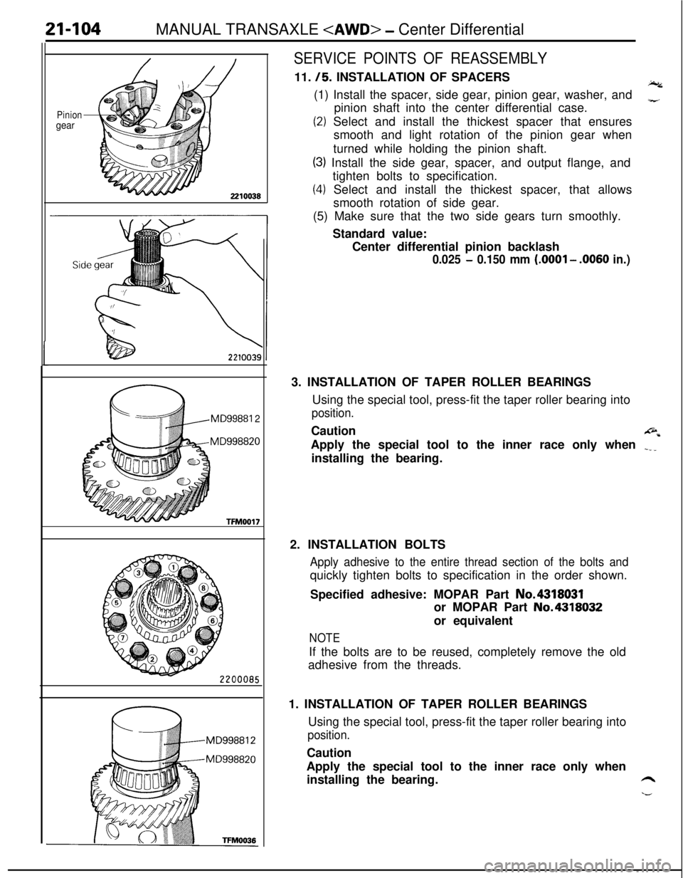
SERVICE POINTS OF REASSEMBLY11.
/5. INSTALLATION OF SPACERSI.(1) Install the spacer, side gear, pinion gear, washer, and
pinion shaft into the center differential case.
z
(2) Select and install the thickest spacer that ensures
smooth and light rotation of the pinion gear when
turned while holding the pinion shaft.
(3) Install the side gear, spacer, and output flange, and
tighten bolts to specification.
(4) Select and install the thickest spacer, that allows
smooth rotation of side gear.
(5) Make sure that the two side gears turn smoothly.
Standard value:
Center differential pinion backlash
0.025 - 0.150 mm (.OOOl - .0060 in.)3. INSTALLATION OF TAPER ROLLER BEARINGS
Using the special tool, press-fit the taper roller bearing into
position.Caution
@*Apply the special tool to the inner race only when
.___installing the bearing.
2. INSTALLATION BOLTS
Apply adhesive to the entire thread section of the bolts andquickly tighten bolts to specification in the order shown.
Specified adhesive: MOPAR Part No.4318031
or MOPAR Part No.4318032
or equivalent
NOTEIf the bolts are to be reused, completely remove the old
adhesive from the threads.
1. INSTALLATION OF TAPER ROLLER BEARINGS
Using the special tool, press-fit the taper roller bearing into
position.Caution
Apply the special tool to the inner race only when
installing the bearing.
6
h--
Page 877 of 1216

AUTOMATIC TRANSAXLE - Troubleshooting214%3
TRANSAXLE CONTROL UNIT
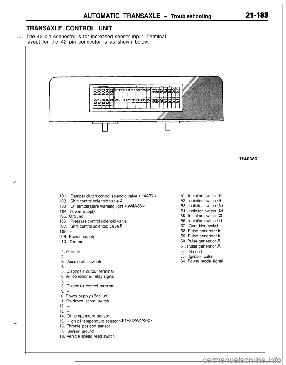
-‘” .The 42 pin connector is for increased sensor input. Terminal
layout for the 42 pin connector is as shown below.TFA0360
101.Damper clutch control solenoid valve
102.Shift control solenoid valve A
103.Oil temperature warning light 104. Power supply
105. Ground
106.Pressure control solenoid valve
107.Shift control solenoid valve B108.
-
109. Power supply
110. Ground
1. GroundL.
-
3.Accelerator switch
4.-5. Diagnosis output terminal
6. Air conditioner relay signal
7.-8. Diagnosis control terminal
9.-
IO. Power supply (Backup)
11. Kickdown servo switch
12.-
13.-14. Oil temperature sensor
15.High oil temperature sensor
16. Throttle position sensor
17.Sensor ground18. Vehicle speed reed switch
51. Inhibitor switch (PI52. Inhibitor switch
(8)53. Inhibitor switch
(N)54. Inhibitor switch
(D)
55. Inhibitor switch (2)56. inhibitor switch
(L)
57.Overdrive switch
58. Pulse generator
B59. Pulse generator
B60. Pulse generator A
61. Pulse generator A
62.Ground63.Ignition pulse64. Power mode signal
Page 898 of 1216
21-204AUTOMATIC TRANSAXLE - Troubleshooting
c;_----__---___-.
IGNITIONSWITCH(IG2)0
?
3E-7r
0
1UA
\IEjC-53mJ
ca (LB)
POWER/
ECONOMY
;$;;E OVER "r-
D-19A, .
12l!i3Fl3453$
,F
IGHT
3 19 ~lo~ll~l2~la~lq1qls
E
A/T SELECTOR
LEVER POSITION
ILLUMINATIONLIGHT
WITHOUTAU;iUi~;UISE
hf---
II
sP5 11
LIEI
AUTO-
CRUISE
CONTROL
UNIT
Y
-t
______--___---__--------
4
gF
C-61 57_______-__-----_---_-----
J/B
Remark**Mark indicates the oPtional wiringFEI~~I;S for auto-cruise control
Page 905 of 1216

AUTOMATIC TRANSAXLE - Service Adjustment Procedures21-21109A0146
OQMOO45
control lever
control lever
5 mm
Section A-A
(2 in.)Manual
controllever
Switch body
SHIFT LOCK MECHANISM CHECKN21FVAA
1.
2.
3.
4.Check to be sure that, under the following conditions, the
select lever cannot be moved from the
“P” position to any
other position.
Ignition key position: “ACC”
Brake pedal: Not depressedButton: Pressed
Check to be sure that, under the following conditions, the
select lever can be moved smoothly from the “P” position
to other position.
Ignition key position: “ACC”
Brake pedal: Depressed
Button: Pressed
Check to be sure that, under the following conditions, the
select lever can be moved smoothly from the “R” position
to the “P” position.
Ignition key position: “ACC”
Brake pedal: Released
Button: Pressed
If a malfunction is discovered when following the above
checking procedures, either adjust or check the shift lock
cable mechanism. (Refer to
P.21-220.)
INHIBITOR SWITCH ADJUSTMENTNZlFKAJ
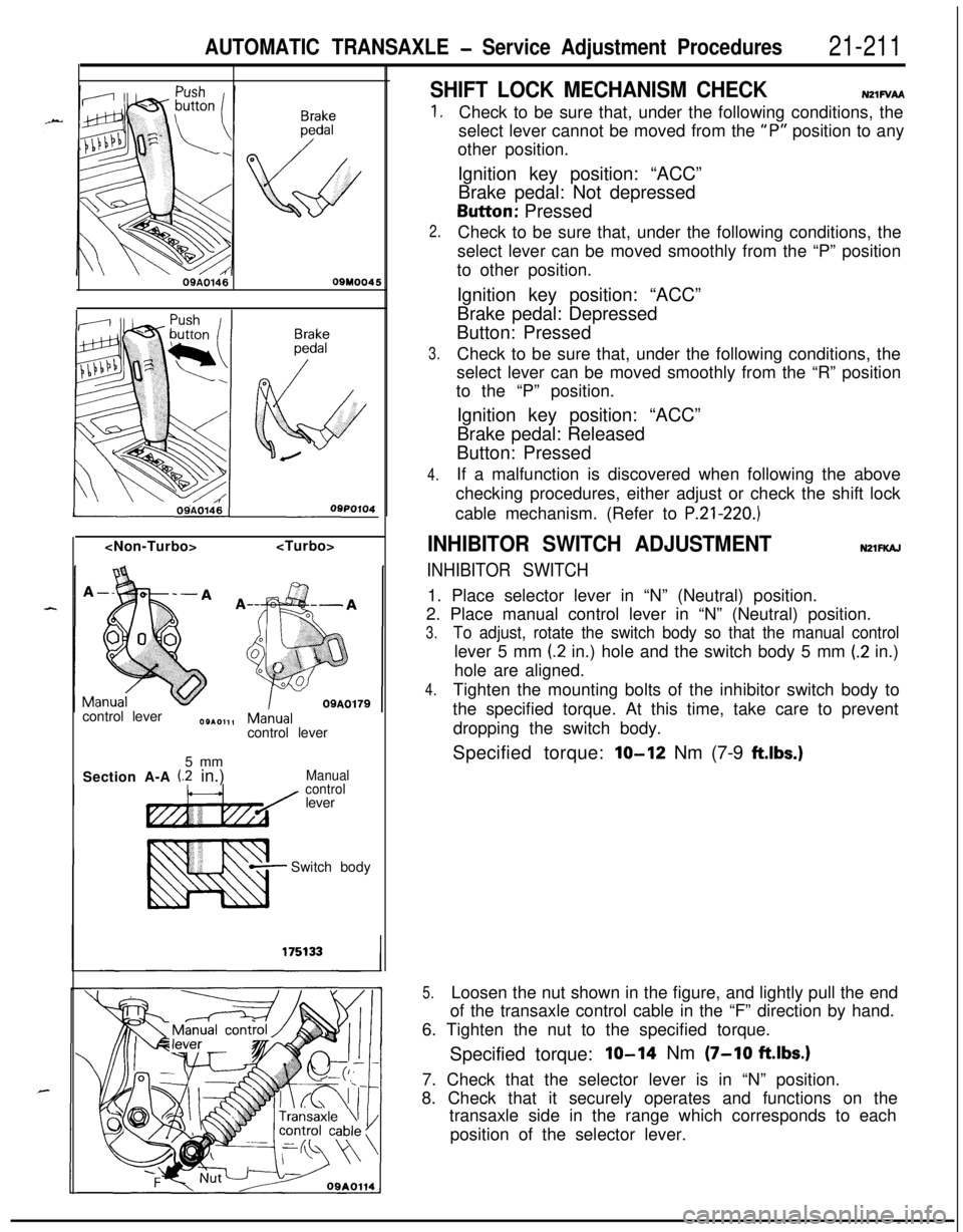
INHIBITOR SWITCH1. Place selector lever in “N” (Neutral) position.
2. Place manual control lever in “N” (Neutral) position.
3.To adjust, rotate the switch body so that the manual controllever 5 mm
(2 in.) hole and the switch body 5 mm (.2 in.)
hole are aligned.
4.Tighten the mounting bolts of the inhibitor switch body to
the specified torque. At this time, take care to prevent
dropping the switch body.
Specified torque:
lo-12 Nm (7-9 ftlbs.)
5.Loosen the nut shown in the figure, and lightly pull the end
of the transaxle control cable in the “F” direction by hand.
6. Tighten the nut to the specified torque.
Specified torque:
IO-14 Nm (7-10 ftlbs.)7. Check that the selector lever is in “N” position.
8. Check that it securely operates and functions on the
transaxle side in the range which corresponds to each
position of the selector lever.
Page 914 of 1216

AUTOMATIC TRANSAXLE - Transaxle Control
:lemotJnt
\\ \09R0058
09AO143
/’
\
’ CoverCoverKey interlock cableOSA0125
OSAO12629. INSTALLATION OF CLIP
When connecting the control cable to the transaxle mount
,-bracket, install the clip until it contacts the control cable, in
the position shown in the figure.
,”l ADJUSTMENT OF TRANSAXLE CONTROL CABLE
Refer to the section concerning adjustment of the inhibitor
switch. (Refer to P.21-211.)
23. INSTALLATION OF SHIFT LOCK CABLE (SELECT LEVERASSEMBLY SIDE)
(1) Move the select lever to the “R” position.
(2) Clamp the shift lock cable.
(3) Connect the shift lock cable to the select lever
assembly, and temporarily tighten the nut.
(4) Slide the shift lock cable so that the distance between
the select lever assembly’s detent pin and the end of
the shift lock cable is the standard value, and then
tighten the nut at the specified torque.
Standard value (A):
l-4 mm (.04-.I5 in.)
(5) After connecting the shift lock cable, check the shift
lock mechanism. (Refer to P.21-211.)
22. INSTALLATION OF THE SLIDE LEVERI21. KEY INTER-
LOCK CABLE (STEERING LOCK ASSEMBLY SIDE)
(1) With the ignition key either at the “LOCK” position or
removed, install the slide lever to the key cylinder.
(2) Connect, as shown in the figure, the key interlock cable
to the slide lever and the key cylinder.
(3) Apply a light coating of multipurpose grease where
shown in the figure.
Grease: MOPAR Multi-mileage Lubricant Part
No. 2525035 or equivalent
(4) Install the key interlock cable.
18. INSTALLATION OF KEY INTERLOCK CABLE (SELECT
LEVER ASSEMBLY SIDE)
(1) Move the select lever to the “P” postion.(2) Connect the key interlock cable to the select lever
assembly’s lock cam. Be sure that the spring installed
to the key interlock cable is as shown in the figure.
*(3) While gently pressing the lock cam in the
F direction,-tighten the nut to secure the key interlock cable.
(4) After connecting the key interlock cable, check the key
interlock mechanism. (Refer to ‘P.21-210.)
Page 948 of 1216

AUTOMATIC TRANSAXLE - Transaxle Assemblv
Solder
220004858. Install new O-ring in groove of oil pump housing and apply
automatic transmission fluid lightly to outside surface of
O-ring.e59. Install oil pump assembly by tightening six bolts evenly.
i-When installing this oil pump assembly, be careful that
thrust washer will not drop.
60. Check input shaft end play. Readjust if necessary (see step
53).Standard value
: 0.3-1.0 mm (.012-,040 in.)
61, Apply solder [length approx. 10 mm (40 in.) and diameter
1.6 mm (.06 in.) to the differential assembly at the locationsshown in the illustration.
“I
-4--J62. Install the converter housing without gasket.
Caution
Don’t reuse the rubber coated metal gasket which has
been used once.
63. Tighten bolts to specification.
64. Loosen the bolts and remove the converter housing in
order to remove the pieces of solder. If the solder is not
broken, carry out the work in steps (61) to (64) with large
diameter solder.
65. Using a micrometer, measure the thickness of the flattned
solder.Select the spacer in the following manner according to
measurement.Add the thickness
[0.38 mm (015 in.)] of the rubber coated
metal gasket and the end play
LO-O.1 5 mm (O-.006 in.)] ofi4the differential case to the measurement
(T). Select a -spacer which is in the calculated range, In other words,
select a spacer whose thickness is in the range of n+ 0.38mm
(.015 in.)] to [T+ 0.38 mm (.015 in.) - 0.15 mm (.006
in.)].