Page 1169 of 1216

HEATERS AND AIR CONDITIONING - Service Adjustment Procedures 24-25
16A1077
20AO499
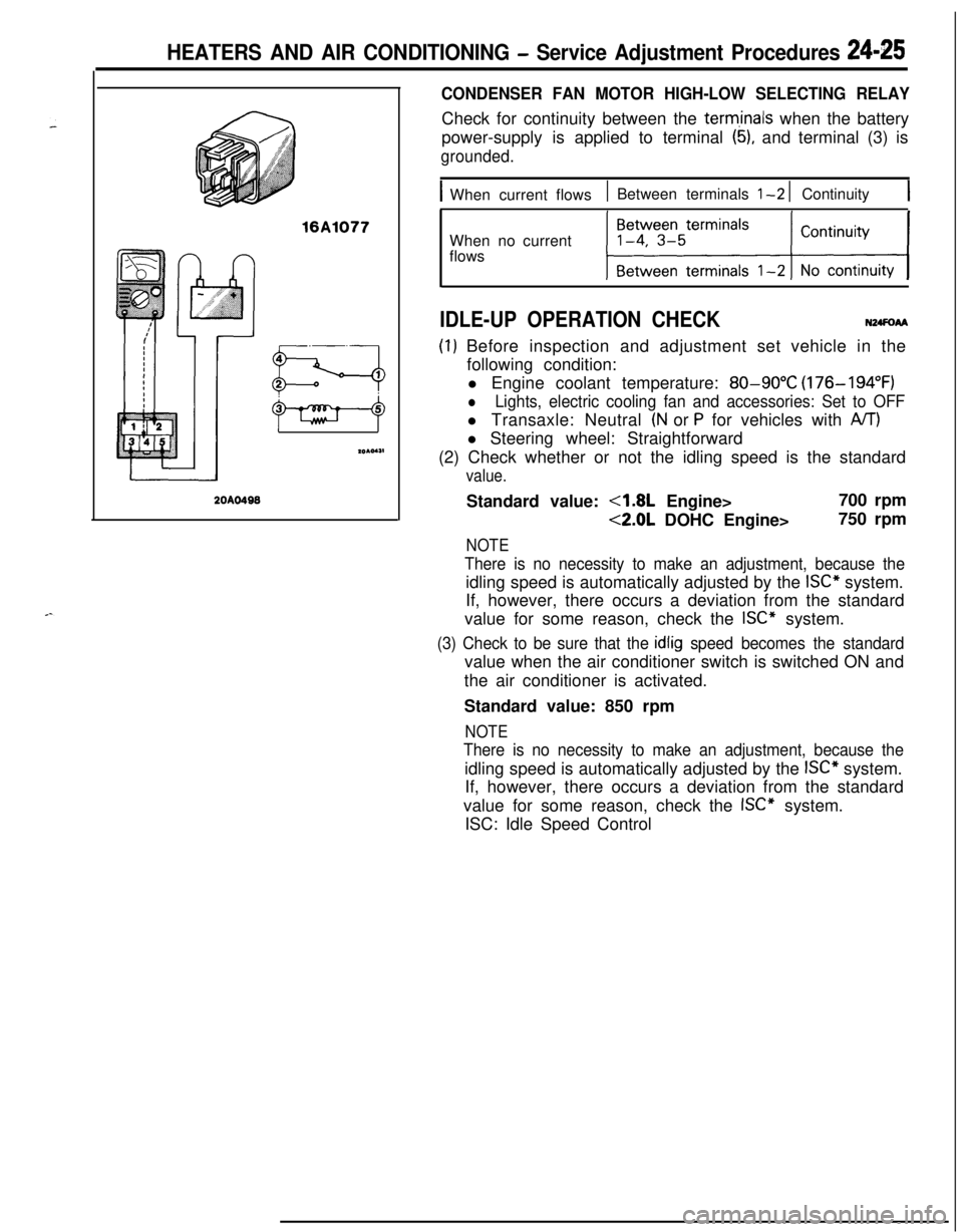
CONDENSER FAN MOTOR HIGH-LOW SELECTING RELAYCheck for continuity between the
term,inals when the battery
power-supply is applied to terminal
(5), and terminal (3) is
grounded.
IWhen current flows1 Between terminals l-2 1 Continuity1When no current
flows
IDLE-UP OPERATION CHECKN24FoAA
(I) Before inspection and adjustment set vehicle in the
following condition:
l Engine coolant temperature:
80-90°C (176-194°F)
lLights, electric cooling fan and accessories: Set to OFFl Transaxle: Neutral
(N or P for vehicles with A/T)l Steering wheel: Straightforward
(2) Check whether or not the idling speed is the standard
value.Standard value:
4.8L Engine>700 rpm
<2.0L DOHC Engine>750 rpm
NOTE
There is no necessity to make an adjustment, because theidling speed is automatically adjusted by the
ISC” system.
If, however, there occurs a deviation from the standard
value for some reason, check the
ISC” system.
(3) Check to be sure that the idlig speed becomes the standardvalue when the air conditioner switch is switched ON and
the air conditioner is activated.
Standard value: 850 rpm
NOTE
There is no necessity to make an adjustment, because theidling speed is automatically adjusted by the
ISC” system.
If, however, there occurs a deviation from the standard
value for some reason, check the
ISC” system.
ISC: Idle Speed Control
Page 1186 of 1216
COMPRESSOR
DISASSEMBLY AND REASSEMBLY24-28 Nm
18-21
ft.lbs.Magnetic clutch disassembly steps
4eW ;. tIu;h hub
3:Snap ring4*4.Rotor
5. Snap ring
l 46.Clutch coilShaft seal disassembly steps
4*
l + ;. F;;t housing
9:Felt holder
10.Snap ring
4e l + 11. Shaft seal
12.O-ring
NOTE(1) Reverse the disassembly procedures to reassemble.(2) ~~ : Refer to “Service Points of Disassembly”.
(3) W : Refer to “Service Points of Reassembly”.(4) m : Non-reusable parts.
ISERVICE POINTS OF DISASSEMBLYN24SFAC\
2OW857
\1. REMOVAL OF CLUTCH HUB
(1) Fix the compressor with a vise. At this time, the rear
housing of the compressor must be in contact with the
vise.(2) If the clutch hub cannot be pulled off by hand, screw in
an 8 mm
(.315 in.) completely threaded bolt so as to
raise the clutch hub so it can be removed.
4. REMOVAL OF ROTOR
Using a plastic hammer, lightly tap the rotor off the shaft.
Page 1200 of 1216
25-4EMISSION CONTROL SYSTEMS - Vacuum HosesVACUUM HOSES
VACUUM HOSES ROUTING
1.8L Engine>
hW7JA-
r”
w..’L:
Light blueR:
RedB:
BlackCanister,Purge control
/solenoid valve
Fuel pressure
regulator
Vehicle front
3EM0123
<-LCalifornia- 1.8L Engine>
CanisterThrottle body
aVehicle front G: Green
Y : Yellow
L : Light blueR: Red
B : Black/EGR valve
-Fuel pressure
regulator
3EM0124
Page 1201 of 1216
EMISSION CONTROL SYSTEMS - Vacuum Hoses2515
Canada-2.0L DOHC Engine Non-Turbo>
Purge control
solenoid valve
Canister
Therm0valve
G: Green
Y : Yellow
L : Light blueR: Red
B : Black
nVehicle frontFuel pressure
regulator6EM0191
G: Green
Y : YellowPurge control
solenoid valve
Cani
EGR controlsolenoid valve
EGR valve
L : Light blue
R: Red
B : BlackVehicle frontFuel pressure
regulator
6EM0192
Page 1202 of 1216
25-6EMISSION CONTROL SYSTEMS - Vacuum Hoses
Canada-2.0L DOHC Engine Turbo>
G: Green
Y : Yellow
L : Light blueR: Red
B : Black
W: White
Purge control valvg
Purge controlFuel pressure control,solenoid valve/solenoid valve
Therm0 valve’
el pressure regulator
Turbocharger
vvasre gate actuator Waste gate control
solenoid valveVehicle front
6EM0222
G: Green
Y : Yellow
L : Lrght blueR: Red
B : Black
W: White
1sPurge control valve
&+
Air cleanerFuel pressure control
solenoid valve.
Purge control
solenoid valve\Fuel pressure regulator
Waste gate control
solenord valve
Waste gate actuatorv.,~~‘~y:‘;7Vehicle front
6EM0223
Page 1209 of 1216

EMISSION CONTROL SYSTEMS- Evaporative Emission Control System25-WECl51C
PURGE CONTROL VALVE
INSPECTION
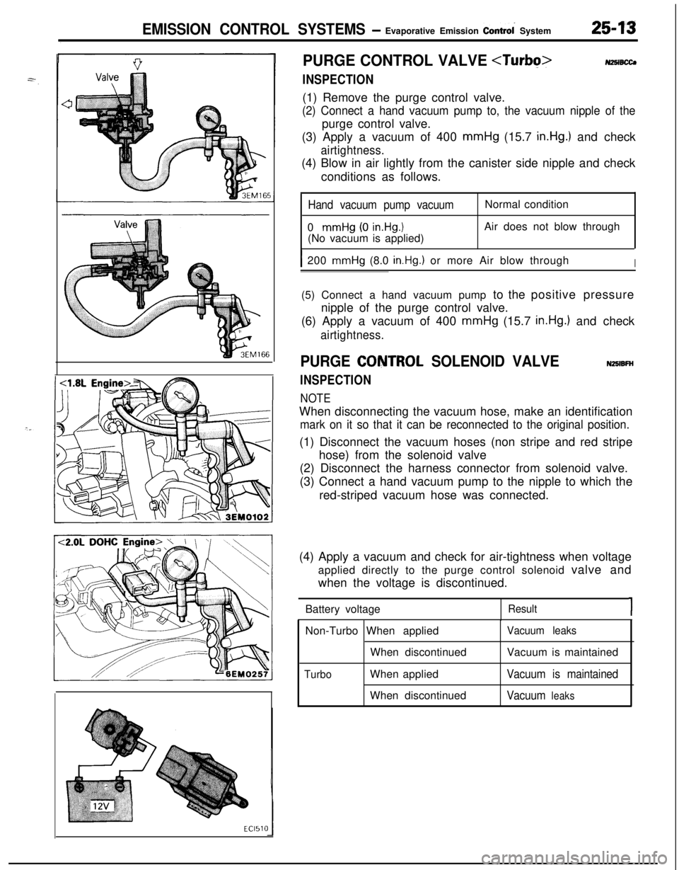
NZSIBCCJ(1) Remove the purge control valve.
(2) Connect a hand vacuum pump to, the vacuum nipple of thepurge control valve.
(3) Apply a vacuum of 400 mmHg (15.7
in.Hg.) and check
airtightness.(4) Blow in air lightly from the canister side nipple and check
conditions as follows.
Hand vacuum pump vacuum0
mmHg (0 in.Hg.1(No vacuum is applied)Normal condition
Air does not blow through
I200 mmHg (8.0 in.Hg.) or more Air blow throughI(5) Connect a hand vacuum pump to the positive pressure
nipple of the purge control valve.
(6) Apply a vacuum of 400 mmHg (15.7
in.Hg.) and check
airtightness.
PURGE CQNTROL SOLENOID VALVE
INSPECTION
NOTE
NZBIBFHWhen disconnecting the vacuum hose, make an identification
mark on it so that it can be reconnected to the original position.(1) Disconnect the vacuum hoses (non stripe and red stripe
hose) from the solenoid valve
(2) Disconnect the harness connector from solenoid valve.
(3) Connect a hand vacuum pump to the nipple to which the
red-striped vacuum hose was connected.
(4) Apply a vacuum and check for air-tightness when voltage
applied directly to the purge control solenoid valve and
when the voltage is discontinued.
Battery voltage
Result1Non-Turbo When applied
When discontinued
TurboWhen applied
When discontinued
Vacuum leaksVacuum is maintained
Vacuum is maintained
Vacuum
leaks
Page 1213 of 1216

EMISSION CONTROL SYSTEMS- Exhaust Gas Recirculation (EGR) Svstem254 7
EGR SYSTEM INSPECTION
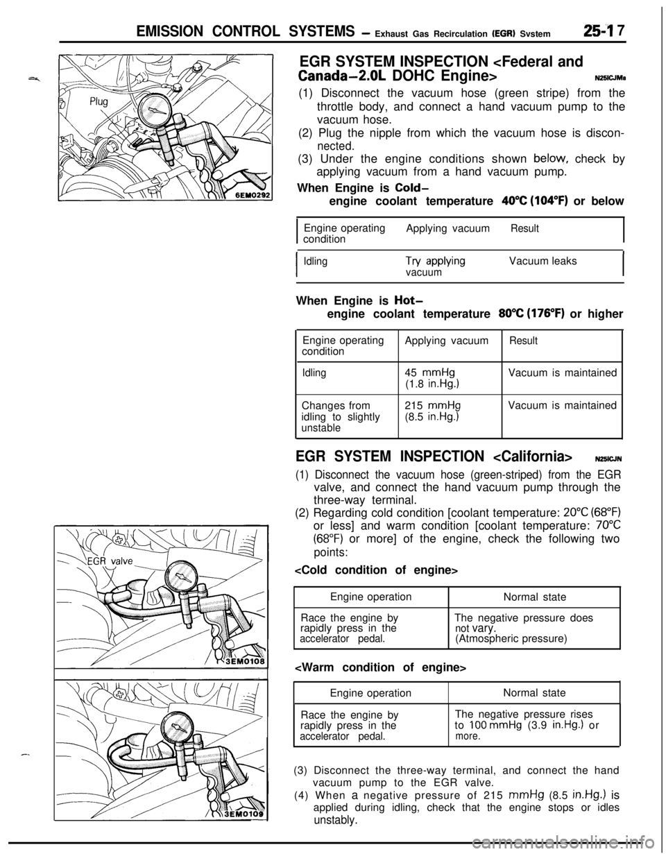
Canada-2.0L DOHC Engine>N25lCJMa(1) Disconnect the vacuum hose (green stripe) from the
throttle body, and connect a hand vacuum pump to the
vacuum hose.
(2) Plug the nipple from which the vacuum hose is discon-
nected.(3) Under the engine conditions shown
below, check by
applying vacuum from a hand vacuum pump.
When Engine is
Cold-engine coolant temperature
40°C (104°F) or below
Engine operating
conditionApplying vacuum
Result
I
IdlingTry awMngVacuum leaksvacuumIWhen Engine is
Hot-engine coolant temperature
80°C (176°F) or higher
Engine operating
conditionApplying vacuum
Result
Idling45
mmHg(1.8
in.Hg.1Vacuum is maintained
Changes from
idling to slightly
unstable215
mmHg(8.5
in.Hg.1Vacuum is maintained
EGR SYSTEM INSPECTION N25lCJN
(1) Disconnect the vacuum hose (green-striped) from the EGRvalve, and connect the hand vacuum pump through the
three-way terminal.
(2) Regarding cold condition [coolant temperature:
20°C (68°F)or less] and warm condition [coolant temperature:
70°C
(68°F) or more] of the engine, check the following two
points:
Engine operation
Normal state
Race the engine byThe negative pressure does
rapidly press in the
not vary.accelerator pedal.(Atmospheric pressure)
Engine operationNormal state
Race the engine by
rapidly press in the
accelerator pedal.The negative pressure rises
to
100 mmHg (3.9 in.Hg.1 ormore.(3) Disconnect the three-way terminal, and connect the hand
vacuum pump to the EGR valve.
(4) When a negative pressure of 215
mmHg (8.5 in.Hg.) is
applied during idling, check that the engine stops or idles
unstably.
Page 1216 of 1216

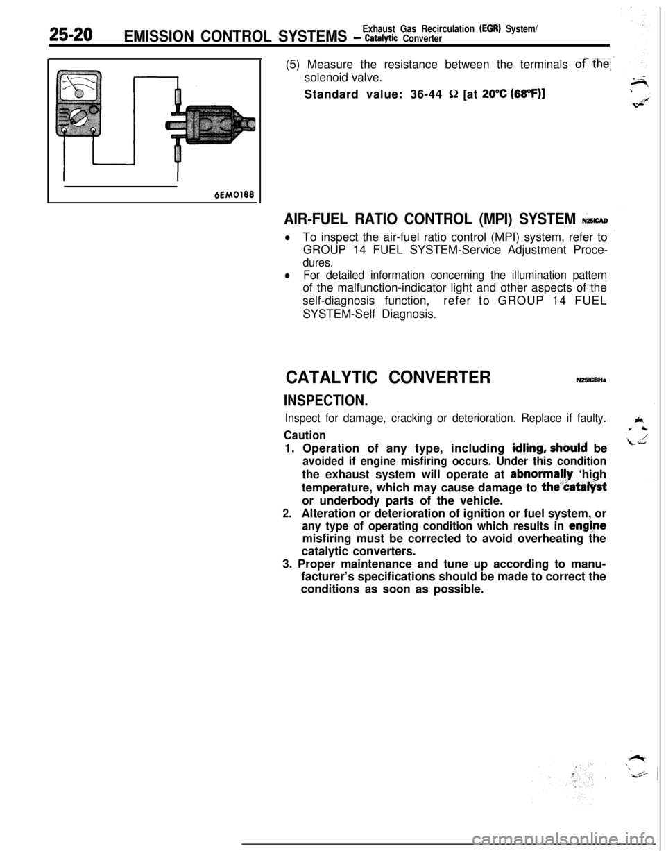
25-20Exhaust Gas Recirculation (EGR) System/EMISSION CONTROL SYSTEMS - ‘catalytic Converter(5) Measure the resistance between the terminals
of- the
Standard value: 36-44
Q [at 20°C (68OF)l
6EM0188
AIR-FUEL RATIO CONTROL (MPI) SYSTEM &CAD
lTo inspect the air-fuel ratio control (MPI) system, refer to
GROUP 14 FUEL SYSTEM-Service Adjustment Proce-
dures.
lFor detailed information concerning the illumination patternof the malfunction-indicator light and other aspects of the
self-diagnosis function,refer to GROUP 14 FUEL
SYSTEM-Self Diagnosis.
CATALYTIC CONVERTERN25lCBHa
INSPECTION.
Inspect for damage, cracking or deterioration. Replace if faulty.
Caution1. Operation of any type, including
idjing, should be
avoided if engine misfiring occurs. Under this conditionthe exhaust system will operate at abnormally ‘high
temperature, which may cause damage to
the”Catalystor underbody parts of the vehicle.
2.Alteration or deterioration of ignition or fuel system, or
any type of operating condition which results in enghtemisfiring must be corrected to avoid overheating the
catalytic converters.
3. Proper maintenance and tune up according to manu-
facturer’s specifications should be made to correct the
conditions as soon as possible.