1991 MITSUBISHI ECLIPSE light
[x] Cancel search: lightPage 526 of 1216

14-72FUEL SYSTEM - MPI Svstem InsDection <2.0L DOHC Engine>
MALFUNCTION INDICATOR LIGHTAmong the self-diagnosis items, a malfunction indicator light
comes on to notify the driver of the emission control items
when an irregularity is detected.
However, when an irregular signal returns to normal and the
engine control unit judges that it has returned to normal. the
malfunction indicator light goes out.
Moreover, when the ignition switch is turned off, the light goes
out. Even if the ignition switch is turned on again, the light doesnot come on until the irregularity is detected.
Here, immediately after the ignition switch is turn on, the
malfunction indicator light is lit for 5 seconds to indicate that
the malfunction indicator light operates normally.
I--l
klfunctionindicator light
Items indicated by the lightening malfunction light
Engine control unit
Oxygen sensor
Air flow sensor
Intake air temperature sensor
Throttle positron sensor
Engrne coolant temperature sensor
Crank angle sensor
Top dead center sensor
Barometric pressure sensor
Detonatron sensor
Injector
Fuel pump
EGR
Ignition co11
/
iMALFUNCTION INDICATOR LIGHT INSPECTION
When turning on the ignition switch, check that the light comes
on.
NOTEIf the light does not come on, check the harness and light for
breakage.
Page 538 of 1216
14-84FUEL SYSTEM - Injector
03*0095
Delivery pipe03A0095-SERVICE POINTS OF REMOVAL
H4s0m1‘~
3.DISCONNECTION OF THE HIGH PRESSURE FlJFL HOSE /;;
Bleed the residual pressure within the fuel pipe line’& as to~prevent the flow of fuel.
For information concerning the method to be folfowed for
bleeding the residual pressure, refer to
P.14-44.Caution
Cover the hose connection with rags to prevent splash,
of fuel that could be caused by some residual pressure
in the fuel pipe line.
12. REMOVAL OF DELIVERY PIPE/ 15. INJECTOR
Remove the deliver-y pipe (with the injectors attached to it).Caution
Care must be taken, when removing the delivery pipe,
not to drop the injector.
INSPEiZTION
INJECTORS
N14NGAA
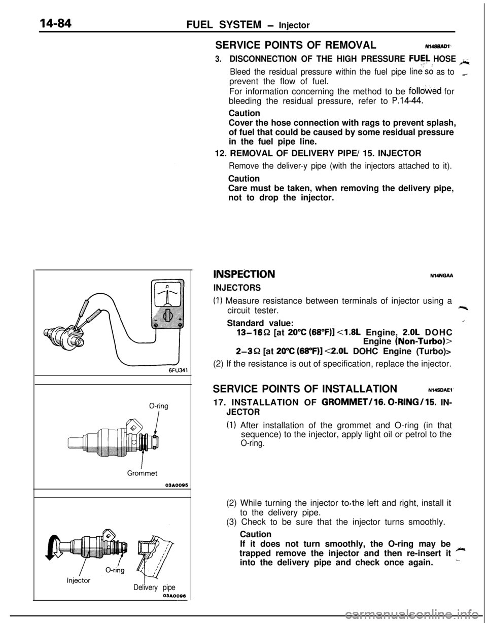
(1) Measure resistance between terminals of injector using a
circuit tester.+-%Standard value:
/13-1652 [at
20°C (68”F)] <1.8L Engine, 2.0L DOHC
Engine
(NoniTurbo)>
2-3Q [at 20°C (68”F)] <2.0L DOHC Engine (Turbo)>
(2) If the resistance is out of specification, replace the injector.
SERVICE POINTS OF INSTALLATION
N14SDAEl’17. INSTALLATION OF
GROMMET/lG. 0-RINGI15. IN-
JECTOR
(I) After installation of the grommet and O-ring (in that
sequence) to the injector, apply light oil or petrol to the
O-ring.(2) While turning the injector to.the left and right, install it
to the delivery pipe.
(3) Check to be sure that the injector turns smoothly.
Caution
If it does not turn smoothly, the O-ring may be
~trapped remove the injector and then re-insert it
into the delivery pipe and check once again.
L
Page 539 of 1216
FUEL SYSTEM - Injector/Throttle Body <1.8L Engine>14-85
Delivery pipe
Fuel pres
regulator
O-ringY pipe
O-kg
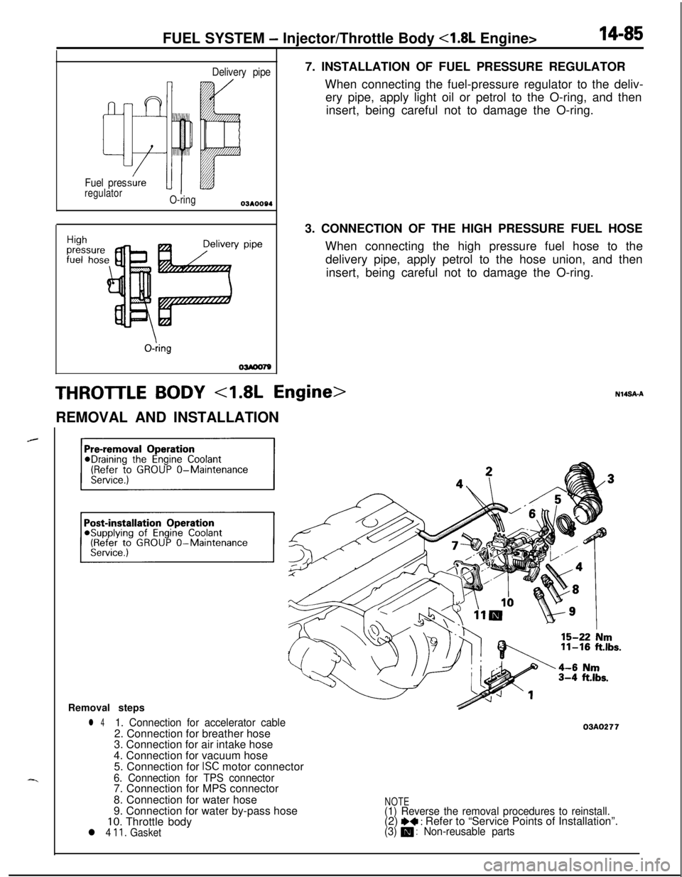
OWOO797. INSTALLATION OF FUEL PRESSURE REGULATOR
When connecting the fuel-pressure regulator to the deliv-
ery pipe, apply light oil or petrol to the O-ring, and then
insert, being careful not to damage the O-ring.
3. CONNECTION OF THE HIGH PRESSURE FUEL HOSE
When connecting the high pressure fuel hose to the
delivery pipe, apply petrol to the hose union, and then
insert, being careful not to damage the O-ring.
THROTTLE BODY 4.8L Engine>REMOVAL AND INSTALLATION
Removal steps
l 41. Connection for accelerator cable2. Connection for breather hose
3. Connection for air intake hose
4. Connection for vacuum hose
5. Connection for
ISC motor connector
6. Connection for TPS connector7. Connection for MPS connector
8. Connection for water hose
9. Connection for water by-pass hose
10. Throttle bodyl 4 11. Gasket
03AO277
NOTE(1) Reverse the removal procedures to reinstall.(2) I)+ : Refer to “Service Points of Installation”.(3) m : Non-reusable parts
Page 548 of 1216
14-94FUEL SYSTEM - Fuel Tank
Outlet side_ Inlet side01
W838
Positioning projection
03A0220SERVICE POINTS OF REMOVALtilirro8AH
6. DISCONNECTION OF HIGH PRESSURE FUEL
H;OSECaution
Cover the hose connection with rags to prevent splash
of fuel that could be caused by some residual pressure
in the fuel pipe line.
INSPECTIONN14GCAll Check the hoses and the pipes for crack or damage.
l Check the fuel tank cap for malfunction.
l Check the fuel tank for deformation, corrosion or crack.
0,. Check the fuel tank for dust or foreign material.
NOTE
If the inside of the fuel tank is to be cleaned, use any one ofthe following:
(1) Kerosene
(2)
Trichloroethylene-(3) A neutral emulsion type detergent
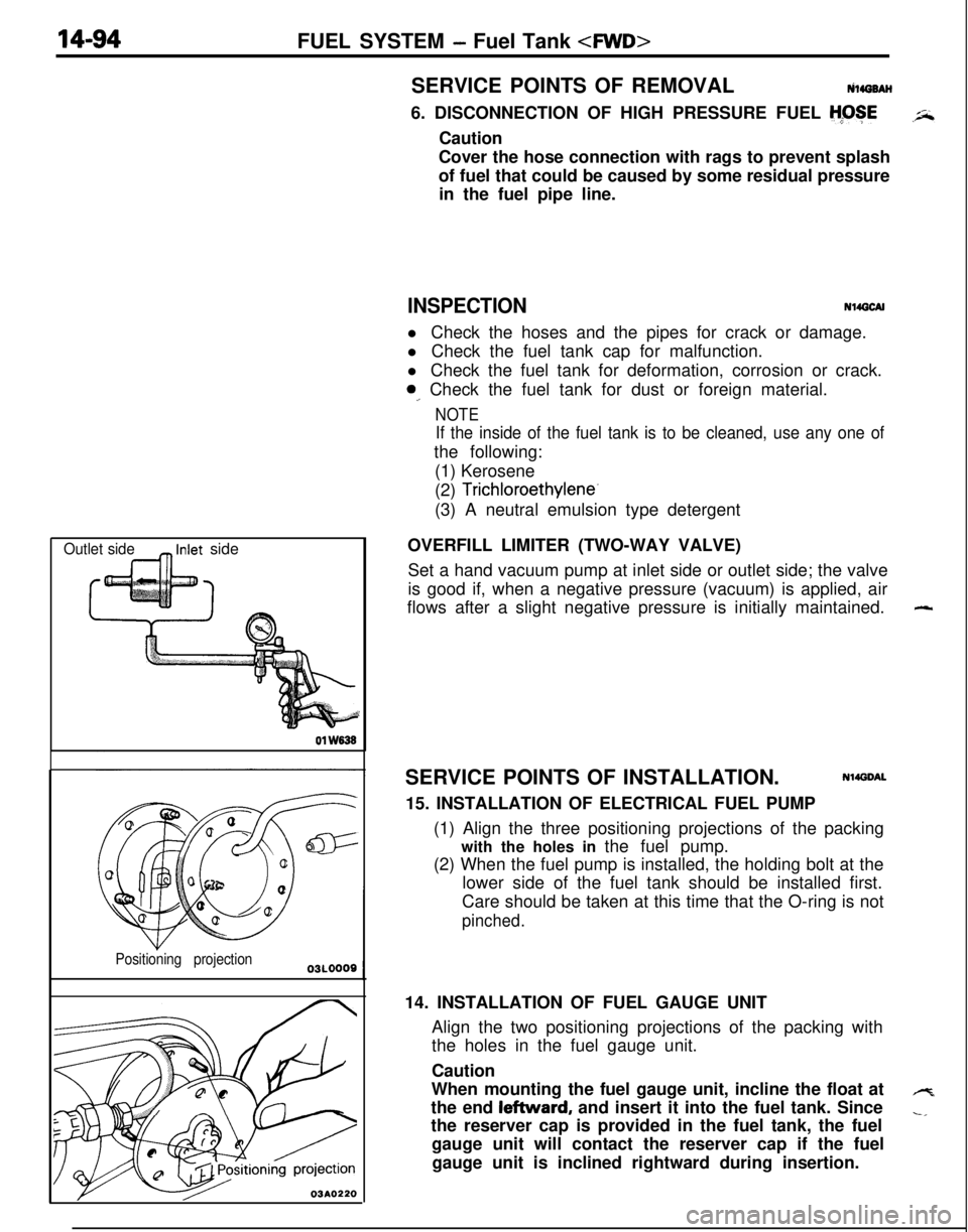
OVERFILL LIMITER (TWO-WAY VALVE)
Set a hand vacuum pump at inlet side or outlet side; the valve
is good if, when a negative pressure (vacuum) is applied, air
flows after a slight negative pressure is initially maintained.
SERVICE POINTS OF INSTALLATION.
Nl4DDAL15. INSTALLATION OF ELECTRICAL FUEL PUMP
(1) Align the three positioning projections of the packing
with the holes in the fuel pump.
(2) When the fuel pump is installed, the holding bolt at the
lower side of the fuel tank should be installed first.
Care should be taken at this time that the O-ring is not
pinched.14. INSTALLATION OF FUEL GAUGE UNIT
Align the two positioning projections of the packing with
the holes in the fuel gauge unit.
Caution
When mounting the fuel gauge unit, incline the float at
the end leftward, and insert it into the fuel tank. Since
the reserver cap is provided in the fuel tank, the fuel
gauge unit will contact the reserver cap if the fuel
gauge unit is inclined rightward during insertion.
-
4
-,
Page 552 of 1216
14-98FUEL SYSTEM -Fuel Tank
W636
Positioning projection03AO257
\03A0256SERVICE POINTS OF REMOVAL
N14G6AHl6. DISCONNECTION OF HIGH PRESSURE FUEL
HGSECaution
Cover the hose connection with rags to prevent splash
of fuel that could be caused by some residual pressure
in the fuel pipe line.
INSPECTIONN14GCAHl Check the hoses and the pipes for crack or damage.
l Check the fuel tank cap for malfunction.
l Check the fuel tank for deformation, corrosion or crack.
l Check the fuel tank for dust or foreign material.
NOTE
If the inside of the fuel tank is to be cleaned, use any one ofthe following:
(1) Kerosene
(2) Trichloroethylene
(3) A neutral emulsion type detergent
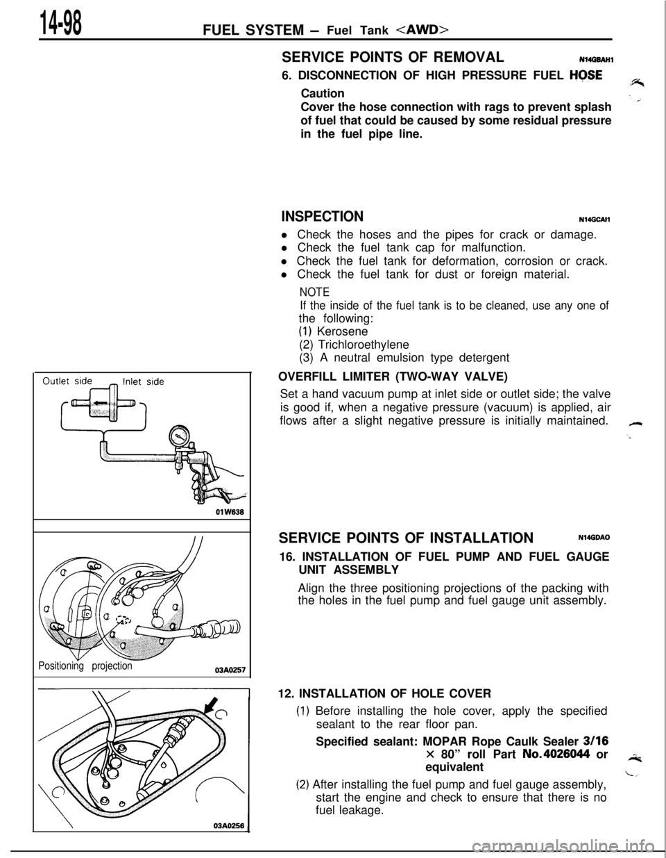
OVERFILL LIMITER (TWO-WAY VALVE)
Set a hand vacuum pump at inlet side or outlet side; the valve
is good if, when a negative pressure (vacuum) is applied, air
flows after a slight negative pressure is initially maintained.
SERVICE POINTS OF INSTALLATION
N14GDAO16. INSTALLATION OF FUEL PUMP AND FUEL GAUGE
UNIT ASSEMBLY
Align the three positioning projections of the packing with
the holes in the fuel pump and fuel gauge unit assembly.
12. INSTALLATION OF HOLE COVER
) Before installing the hole cover, apply the specified
sealant to the rear floor pan.
Specified sealant: MOPAR Rope Caulk Sealer
3116
x 80” roll Part No.4026044 or
equivalent
!) After installing the fuel pump and fuel gauge assembly,
start the engine and check to ensure that there is no
fuel leakage.
Page 560 of 1216
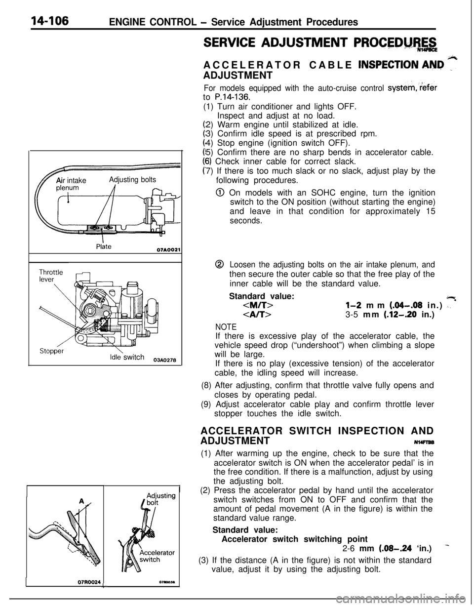
14-106ENGINE CONTROL - Service Adjustment Procedures
TAir intakeAdjusting bolts
Idle switch03A,,2.8
07RQ024L
I
SERVICE ADJUSTMENT PROCEDM%,&ACCELERATOR CABLE
CNSPECTION AN&I ”ADJUSTMENT
For models equipped with the auto-cruise control systemreferto
P.14-136.(1) Turn air conditioner and lights OFF.
Inspect and adjust at no load.
2) Warm engine until stabilized at idle.
3) Confirm idle speed is at prescribed rpm.
4) Stop engine (ignition switch OFF).
5) Confirm there are no sharp bends in accelerator cable.
6) Check inner cable for correct slack.
7) If there is too much slack or no slack, adjust play by the
following procedures.
@ On models with an SOHC engine, turn the ignition
switch to the ON position (without starting the engine)
and leave in that condition for approximately 15
seconds.@
Loosen the adjusting bolts on the air intake plenum, andthen secure the outer cable so that the free play of the
inner cable will be the standard value.
Standard value:
jlr
3-5 mm (.12-.20 in.)
NOTEIf there is excessive play of the accelerator cable, the
vehicle speed drop (“undershoot”) when climbing a slope
will be large.
If there is no play (excessive tension) of the accelerator
cable, the idling speed will increase.
(8) After adjusting, confirm that throttle valve fully opens and
closes by operating pedal.
(9) Adjust accelerator cable play and confirm throttle lever
stopper touches the idle switch.
ACCELERATOR SWITCH INSPECTION AND
ADJUSTMENT
NlWlEB(1) After warming up the engine, check to be sure that the
accelerator switch is ON when the accelerator pedal’ is in
the free condition. If there is a malfunction, adjust by using
the adjusting bolt.
(2) Press the accelerator pedal by hand until the accelerator
switch switches from ON to OFF and confirm that the
amount of pedal movement (A in the figure) is within the
standard value range.
Standard value:
Accelerator switch switching point
2-6 mm
(.08-.24 ‘in.)
(3) If the distance (A in the figure) is not within the standard
value, adjust it by using the adjusting bolt.
Page 563 of 1216

AUTO-CRUISE CONTROL SYSTEM - Snecifications14-109
AUTO-CRUISE CONTROL SYSTEM
.-4.
SPECIFICATIONS
GENERAL SPECIFICATIONSNUCA-B
ItemsSpecifications
Auto-cruise control switch
Rated load AMAIN3.OkO.5
SET0.2fO.l
RESUME0.2kO.l
Voltage drop V0.2 or less
Stop light switch
Rated load A0.1-0.9
Voltage drop (at rated load)V0.25 or less
Clutch switch
Rated load A0.005-l
Voltage drop (at rated load)V0.15 or less
Auto-cruise control unit
Range of speed controlkm/h (mph)40 (25)_+3 (1.81-145 (90)_+5 (3.1)
Auto-cruise control actuator
Drive systemVacuum type
Strokemm (in.)38-42 (1.5-I .7)
Auto-cruise vacuum pump
Rated load A0.4 or less
SERVICE SPECIFICATIONSItems
Accelerator cable playmm (in.)
4l-bThrottle
cable playmm (in.)
Auto-cruise cable playmm (in.)
Control valve, Release valve resistanceQ
Specifications
O-l (O-.04)
2-3 (.08-,121
1-2 (.04-.08)
1-2 (.04-.08)
50-60
TORQUE SPECIFICATIONSN14CGCItems
Nmftlbs.
Link protector4-63-4-.
Link assembly9-147-10
Auto-cruise vacuum pump4-63-4
Accelerator cable plate4-63-4
Page 565 of 1216

AUTO-CRUISE CONTROL SYSTEM - Troubleshooting144w
Auto-cruise control system cannot be set.
NOTEThis chart is to be used, then, for troubleshooting if it is not
possible to use the self-diagnosis for checking.
Prepare to conduct input check.
)( (Refer to P.14lrWhere codes
No.21, 22, 23, 25 and 26disolaved when, with the vehicle stationary,the’ input check codes were recalled?
‘#
No-8
cArc-3 ttie results of all inout checks normals?
L--y--
I
Check resultsProbable causeRemedy
ii”,:” chart
Code 21 remains even though SETSET switch ON mal-Replace the controlNo.2switch
is set to OFF.functionswitch
SET switch input lineRepair the harnessshort-circuit
:-Code 22 remains even though RE-SUME switch is set to OFF.RESUME switch ONmalfunction
RESUME switch input
line short-circuit
Replace the controlswitch
Repair the harnessNo.3
Code 23 is not canceled even if theMalfunction of stopReplace stop lightNo.6stop light switch
is turned OFF bylight switch circuit.switch or repair har-
releasing the brake pedal.ness.
Code 25 does not disappear, andMalfunction of theCheck or repair theNo.4
code 24 does not appear, evenvehicle-speed sensorvehicle speed sensor
though vehicle speed reaches appro-circuit (damaged or dis-circuit.ximately
40 km/h (25 mph) or higher.connected wiring, orshort-circuit)
Code 26 is not canceled even if theclutch switch is turned OFF by re-leasing the clutch pedal.Malfunction of clutch
switch circuit.
Replace clutch switchNo.8or repair harness.
Code 26 is not canceled even if theMalfunction of inhibitorReplace inhibitor switchNo. 7select lever is moved to anything butswitch circuit.or repair harness.
N, P
the auto-cruise vacuum pump circuit.NOTE_. . . e_,1 (Go to check chart No.5.)IIf the results of the check oT tne auro-crutse vacuum pump
circuit (check chart No. 5) and of the auto-cruise vacuum pump
and actuator itself (P.14-138.) reveal no abnormal
condition,replace
the electronic control unit (ECU).
-.