1991 MITSUBISHI ECLIPSE ignition
[x] Cancel search: ignitionPage 533 of 1216

FUEL SYSTEM - MPI System Inspection <2.0L QOHC Engine>14-79EGR TEMPERATURE SENSOR
N14RCHAaRefer to GROUP 25
- Exhaust Gas Recirculation System.
VEHICLE SPEED SENSOR
Refer to GROUP 8
- Meters and Gauges.
N140EBBaAIR CONDITIONER SWITCH
Nl4QQAEaRefer to GROUP 8
- Column Switch.
POWER STEERING OIL PRESSURE SWITCH
N14RCJBRefer to GROUP 19 for power steering system inspection.
INJECTORS
NWXAHCHECKING OPERATION SOUND
Using a sound-scope, check the operation sound (“chi-chi-chi”)of the injectors during idling or during cranking.
Check to be sure that the operation sound increases when the
engine speed is increased.
Caution
Note that the sounds of other injectors may be heard even
though the injector being checked is not operating, so caremust be taken when checking.
NOTEIf the operation sounds cannot be heard, check the injector
activation circuit.
If this circuit is normal, there is probably a malfunction of the
injector or of the engine control unit.
MEASURING OF RESISTANCE BETWEEN TERMINALS
(1) Disconnect the connector for the injectors.
(2) Measure the resistance between terminals.
Standard value:
-16 S2 [at 20°C (68”F)]
- 3 52 [at 20% (68”F)]
(3) Connect the connector for the injectors.
IDLE SPEED CONTROL SERVO
N14QUADCHECKING OPERATING SOUND
(1) Check that when the ignition switch is placed in the ON
position (the engine not started), the operating sound of thestepper motor can be heard over the idle speed control
servo.
(2) If no operating sound can be heard, check the stepper
motor drive circuit.
(If the circuit is good, a defective stepper motor or engine
control unit is suspected.)
Page 536 of 1216

14-82FUEL SYSTEM - MPI System Inspection <2.0L DOHC Engine>
\ \\I \3FUO352
,\ \
\I \3FUO353
,\ ‘\R/
\ \\I \3FUo354
POWER TRANSISTORRefer to GROUP 8
- Ignition System
NlIAcQAl
a-4
AIR CONDITIONER POWER RELAYN14NCl.a -Refer to GROUP 24
- Air Conditioner.
PURGE CONTROL SOLENOID VALVEN14RCKARefer to GROUP 25
- Evaporative Emission Control System.
EGR CONTROL SOLENOID VALVE
N14NCURefer to GROUP 25
- Exhaust Gas Recirculation System.
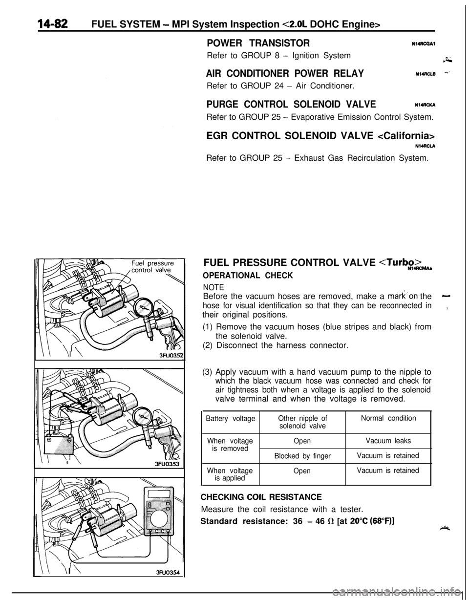
FUEL PRESSURE CONTROL VALVE
NOTEBefore the vacuum hoses are removed, make a mark’on the
-
hose for visual identification so that they can be reconnected in,their original positions.
(1) Remove the vacuum hoses (blue stripes and black) from
the solenoid valve.
(2) Disconnect the harness connector.
(3) Apply vacuum with a hand vacuum pump to the nipple to
which the black vacuum hose was connected and check for
air tightness both when a voltage is applied to the solenoidvalve terminal and when the voltage is removed.
Battery voltageOther nipple of
solenoid valveNormal condition
When voltage
is removed
When voltage
is applied
OpenVacuum leaks
Blocked by fingerVacuum is retained
OpenVacuum is retainedCHECKING
COIL RESISTANCE
Measure the coil resistance with a tester.
Standard resistance: 36
- 46 R [at 20°C (68”F)]
Page 560 of 1216

14-106ENGINE CONTROL - Service Adjustment Procedures
TAir intakeAdjusting bolts
Idle switch03A,,2.8
07RQ024L
I
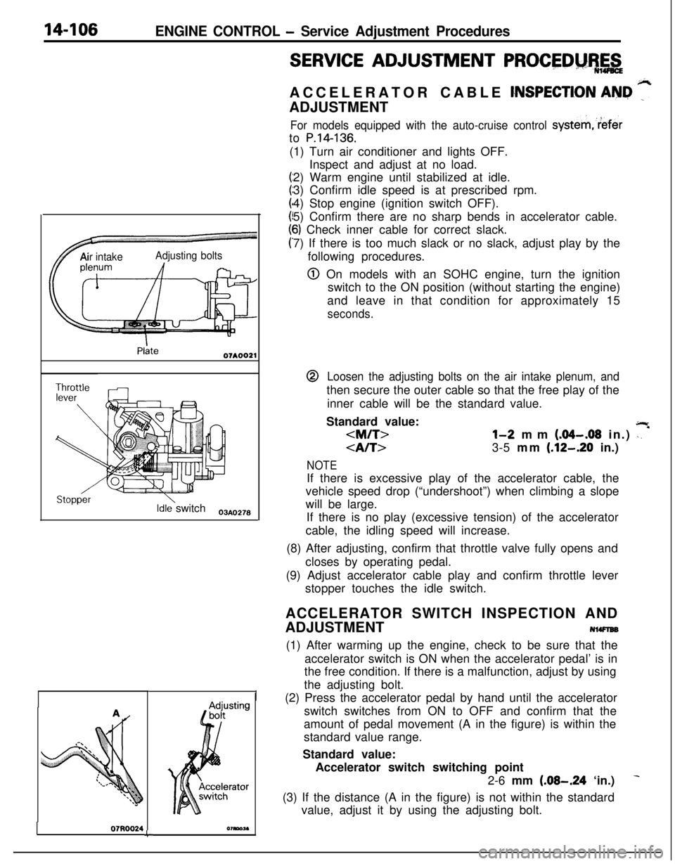
SERVICE ADJUSTMENT PROCEDM%,&ACCELERATOR CABLE
CNSPECTION AN&I ”ADJUSTMENT
For models equipped with the auto-cruise control systemreferto
P.14-136.(1) Turn air conditioner and lights OFF.
Inspect and adjust at no load.
2) Warm engine until stabilized at idle.
3) Confirm idle speed is at prescribed rpm.
4) Stop engine (ignition switch OFF).
5) Confirm there are no sharp bends in accelerator cable.
6) Check inner cable for correct slack.
7) If there is too much slack or no slack, adjust play by the
following procedures.
@ On models with an SOHC engine, turn the ignition
switch to the ON position (without starting the engine)
and leave in that condition for approximately 15
seconds.@
Loosen the adjusting bolts on the air intake plenum, andthen secure the outer cable so that the free play of the
inner cable will be the standard value.
Standard value:
jlr
3-5 mm (.12-.20 in.)
NOTEIf there is excessive play of the accelerator cable, the
vehicle speed drop (“undershoot”) when climbing a slope
will be large.
If there is no play (excessive tension) of the accelerator
cable, the idling speed will increase.
(8) After adjusting, confirm that throttle valve fully opens and
closes by operating pedal.
(9) Adjust accelerator cable play and confirm throttle lever
stopper touches the idle switch.
ACCELERATOR SWITCH INSPECTION AND
ADJUSTMENT
NlWlEB(1) After warming up the engine, check to be sure that the
accelerator switch is ON when the accelerator pedal’ is in
the free condition. If there is a malfunction, adjust by using
the adjusting bolt.
(2) Press the accelerator pedal by hand until the accelerator
switch switches from ON to OFF and confirm that the
amount of pedal movement (A in the figure) is within the
standard value range.
Standard value:
Accelerator switch switching point
2-6 mm
(.08-.24 ‘in.)
(3) If the distance (A in the figure) is not within the standard
value, adjust it by using the adjusting bolt.
Page 568 of 1216

14-114AUTO-CRUISE CONTROL SYSTEM - Troubleshooting
CHECK CHART
1I. CHECKING THE CONTROL UNIT POWER SUPPLY CIRCUIT
Ignition
switch
IAF”7Junction 8
block
tI3
Crurse-controlswitch
OFFDescription of operation
When the cruise control switch (CRUISE) is switched ON whilethe ignition switch is ON, current flows to the ignition switch(IG,), to fuse No.(ll) of the junction block, and to thecruise-control switch (MAIN switch), the control unit, and to
ground.When the ignition switch is turned OFF, the MAIN switch in thecruise control switch is also turned OFF.Troubleshooting hint
ECU terminal voltage
TerminalSignal
No.ConditionsTerminalvoltage
t2Control unitWhen the cruise-System
power supplycontrol switchvoltage
(CRUISE) isswitched ON.
8, 14Control unitAt all timesovground
NOTE+: The connector Nos. in Section “AUTO-CRUISE CONTROL
RELATED HARNESSES” and the connector names in the
junction block are represented.
(Applicable on the next page and subsequence.)13AO3632. CHECKING THE SET SWITCH
Auto-cruisecontrol unitDescription of operation
When the SET switch is switched ON (at the vehicle speed
desired to be maintained, and with the CRUISE switch of the
cruise-control switches ON) that vehicle speed is maintained as
a constanf speed.
Furthermore, the constant speed is gradually reduced (the
“coasting” feature) when the SET switch is pressed and held
while the vehicle is traveling at the previously set constant
speed, and, when the SET switch is released, the vehicle then
maintains that newly set constant speed (the speed at whichthe SET switch was released).
Current flows to the control unit, the cruise control switch
(“SET”), and to ground.Troubleshooting hint
Diagnosis-No. 15 (automatically
cancelled)ECU terminal voltage
1 Terrrnal 1 Signal 1 ConditionsrEl
13AO364
Page 570 of 1216

14-116AUTO-CRUISE CONTROL SYSTEM - Troubleshooting
5. CHECKING THE AUTO-CRUISE CONTROL VACUUM PUMP
Ignitionswitch (IG,)I
SET
ON
Cruise-controlswitchDescription of operation
Hold modeWhen the SET switch is turned ON by the driver turning the
CRUISE switch ON when a determined speed is reached, thecontrol unit receives a set signal, and turns the auto-cruise
vacuum pump motor ON. After the constant speed is reached,
the motor, control valve and release valve are repeatedly turned
ON and OFF according to driving conditions.
Acceleration mode
When the RESUME switch is pressed, the control unit receives
a RESUME signal and it not only turns the auto-cruise vacuum
pump motor ON but also turns the control valve and releasevalve ON (valve is closed).
Deceleration mode
When the SET switch is held down, the control unit receives a
set signal and
it not only turns the auto-cruise vacuum pumpmotor and control valve OFF (valve is opened) but also turns the
release valve ON (valve is closed).
Release modeWhen the CRUISE switch is turned OFF, the control unit
receives a cancel signal and it not only turns the auto-cruisevacuum pump motor OFF but also turns the control valve and
release valve OFF (valve is opened).Troubleshooting hint
Diagnosis-No. 11 (automatically
cancelled)ECU terminal voltage
Page 572 of 1216

14-118AUTO-CRUISE CONTROL SYSTEM - Troubleshooting
8. CHECKING THE CLUTCH SWITCH CIRCUIT
Auto-cruisecontrolunit9
2ClutchswitchOFF ON
1m11Junction
blockI
13AO370Description of operation
If the clutch pedal is pressed wht driving at a constant speed,
the clutch switch is turned ON and a cancel signal is input to the
control unit and the determined driving speed is canceled
because current flows to the clutch, switch junction block from
the control unit and to ground.Troubleshooting hint
ECU terminal voltage
TerminalSignal
No.
1Clutch switch
t--l--II
ConditionsTerminalvoltage
When the clutch
pedal is depressed.
When the clutchpedal is not de-
pressed.
9. CHECKING THE CIRCUITS RELATED TO THE ACCELERATOR SWITCH OFF FUNCTION
Ignition switch
& Accel-/Description of operation
The accelerator switch is a switch that detects the operationalstatus of the accelerator pedal; it is one of the sensors of theautomatic, transaxle.Because the status of the accelerator pedal during constant-speed driving is non-operational, the ground circuit (transistorTr2) of the accelerator switch is switched OFF only during
constant-speed driving in order not to interfere wtth the function
of the automatic transaxle.Troubleshooting hint
ECU terminal voltage
TerminalNo.SignalConditionsTerminalvoltaoe
’ 3Control unitAt all times
power supply
9Accelerator
When the accel-ovswitcherator pedal is
depressed.
When the accel-Systemerator pedal is not
depressed.voltage
\lOTEJC: Indicates ON at all time.
13AO3711 Not in operation ) OFF 1 ON (
Page 575 of 1216

AUTO-CRUISE CONTROL SYSTEM - Troubleshooting'14421
16A065i
Auto-cruise
16LOOS
SELF-DIAGNOSIS CHECKSelf-diagnosis checking is performed when there has been an
automatic cancellation, without cancel switch
operati’on.(1) The following method can be used for checking the
diagnosis. Note that the diagnosis check connector is
located under the driver’s side instrument panel.
Connect a voltmeter between the ground terminal and the
terminal for auto-cruise control of the diagnosis check
connector.It is possible to discover which circuit is the cause of the
cancellation by verifying the indication shown by the
voltmeter with the display patterns shown on the next
page.(2) When the diagnosis code No. is displayed, inspect accord-
ing to the inspection chart No. related to each code No.
NOTECanceling the diagnosis codes
The diagnosis codes remain in memory until the battery is
turned off but they can be canceled in the following ways
without disconnecting the battery terminals.
1. By turning on the ignition switch
2.By turning the cruise switch ON while the SET switch is ONand then, within 1 second, turning the RESUME switch
ON. (Put into condition for input check reception)
3.By turning ON set SET switch and stop light switch at the
same time and continuing the ON condition for 5 seconds
or more.
4.By checking that the diagnosis codes are canceled using avoltmeter.
Page 577 of 1216

AUTO-CRUISE CONTROL SYSTEM - Troubleshooting14:f*L3’.INPUT CHECK
a *:;i’ _Input checks should be made when the
auto-cruise’.contr$system. cannot be set and when it is necessary to check.
(when a malfunction related to the auto-cruise control system,
occurs) whether or not the input signals are
no’rmal.
03A0258
NOTE
1. If inspection of self-diagnosis is necessary, confirm diag-nosis code first and conduct input check.’
2. Input check can be conducted by set operations.
Self-diagnosis terminal outputs display patterns.
3. Display codes are displayed only if the circuit is normal
according to the conditions shown in the table on the next
page.(1) The voltmeter is set in the same way as for the
self-diagnosis check.
(2) Turn the ignition switch to ON and switch OFF the CRUISEswitch.
(3) With the SET switch in the ON position, turn the CRUISE
switch ON. Then, within 1
.O second, place the RESUME
switch in the ON position..
(4) Perform each input operation according to the input check
table (on the next page) and read the codes.
(5) Switch the CRUISE switch OFF.