1991 MITSUBISHI ECLIPSE ignition
[x] Cancel search: ignitionPage 503 of 1216

FUEL SYSTEM - Service Adjustment Procedures <2.0L Engine>14-49
TerminalNo.10screw(2) Disconnect the female connector (for waterproof protec-
tion of the connector) from the connector for ignition timing
adjustment.
(3) Connect the ignition timing adjusting terminal to the groundusing a jumper wire with alligator clips.
(4) Connect terminal No.
10 of the self-diagnosis connector to
the ground with a jumper wire with alligator clips.
(5) Start the engine and run at idle.
(6) Check to be sure that the engine idling speed is the basic
idle speed.
Basic idle speed: 750
250 rpm
If there is a deviation of the engine speed from the basic
idle speed, first determine whether or not the conditions
described below exist, and then use the speed adjustment
screw to adjust to the basic idle speed.
(a) The engine speed may be
20-100 rpm low for a
new vehicle [driven about 500 km (300 miles) or
less], but adjustment is not necessary.
(b) If engine stalling occurs or the engine speed is low
even though the vehicle has been driven about 500
km (300 miles) or more, it is probable that these are
deposits adhered to the throttle valve, so it should
be cleaned.
(Refer to
P.14-51.)(c) If the engine speed is higher than the standard
value even though the speed adjusting screw is
fully close, check for any indication that the idle
position switch (fixed speed adjusting screw) posi-
tion has changed; if there is such an indication,
adjust the idle position switch (fixed speed adjust-
ing screw).
If there is no evidence of a change of position, it is
probable that there is leakage resulting from de-
terioration of the fast-idle air valve (FIAV), so
replace the throttle body.
(7) Turn OFF the ignition switch and stop the engine.
(8) Disconnect the grounding jumper wire from the diagnosis
connector.(9) Disconnect the grounding jumper wire from the ignition
timing connector and mount a waterproof connector.
(1O)Disconnect the tachometer.
(11)Star-t the engine once again and let it idle for about 5
minutes; check to be sure that the idling condition is
normal.
Page 504 of 1216

14-50FUEL SYSTEM - Service Adjustment Procedures <2.0L Engine>THROllLE
POSITION SENSOR ADJUSTME!-T’“.
(1) Slacken the accelerator cable enough.
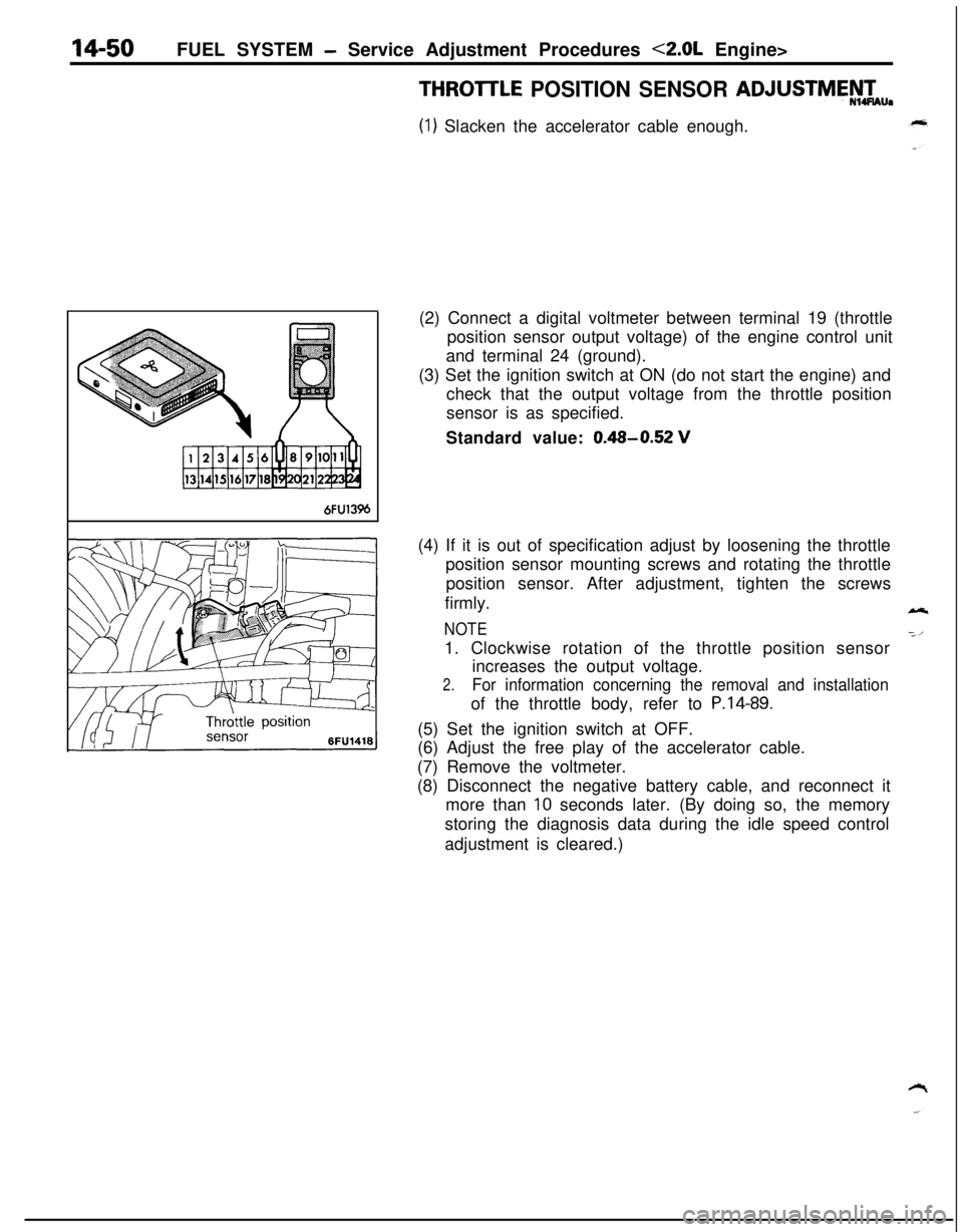
6FU13%(2) Connect a digital voltmeter between terminal 19 (throttle
position sensor output voltage) of the engine control unit
and terminal 24 (ground).
(3) Set the ignition switch at ON (do not start the engine) and
check that the output voltage from the throttle position
sensor is as specified.
Standard value:
0.48-0.52 V(4) If it is out of specification adjust by loosening the throttle
position sensor mounting screws and rotating the throttle
position sensor. After adjustment, tighten the screws
firmly.
NOTE1. Clockwise rotation of the throttle position sensor
increases the output voltage.
2.For information concerning the removal and installationof the throttle body, refer to
P.14-89.(5) Set the ignition switch at OFF.
(6) Adjust the free play of the accelerator cable.
(7) Remove the voltmeter.
(8) Disconnect the negative battery cable, and reconnect it
more than
10 seconds later. (By doing so, the memory
storing the diagnosis data during the idle speed control
adjustment is cleared.)
Page 505 of 1216

FUEL SYSTEM - Service Adjustment Procedures <2.0L Engine>14-51THROTTLE BODY (THROTTLE VALVE AREA)
CLEANINGNl4FtU
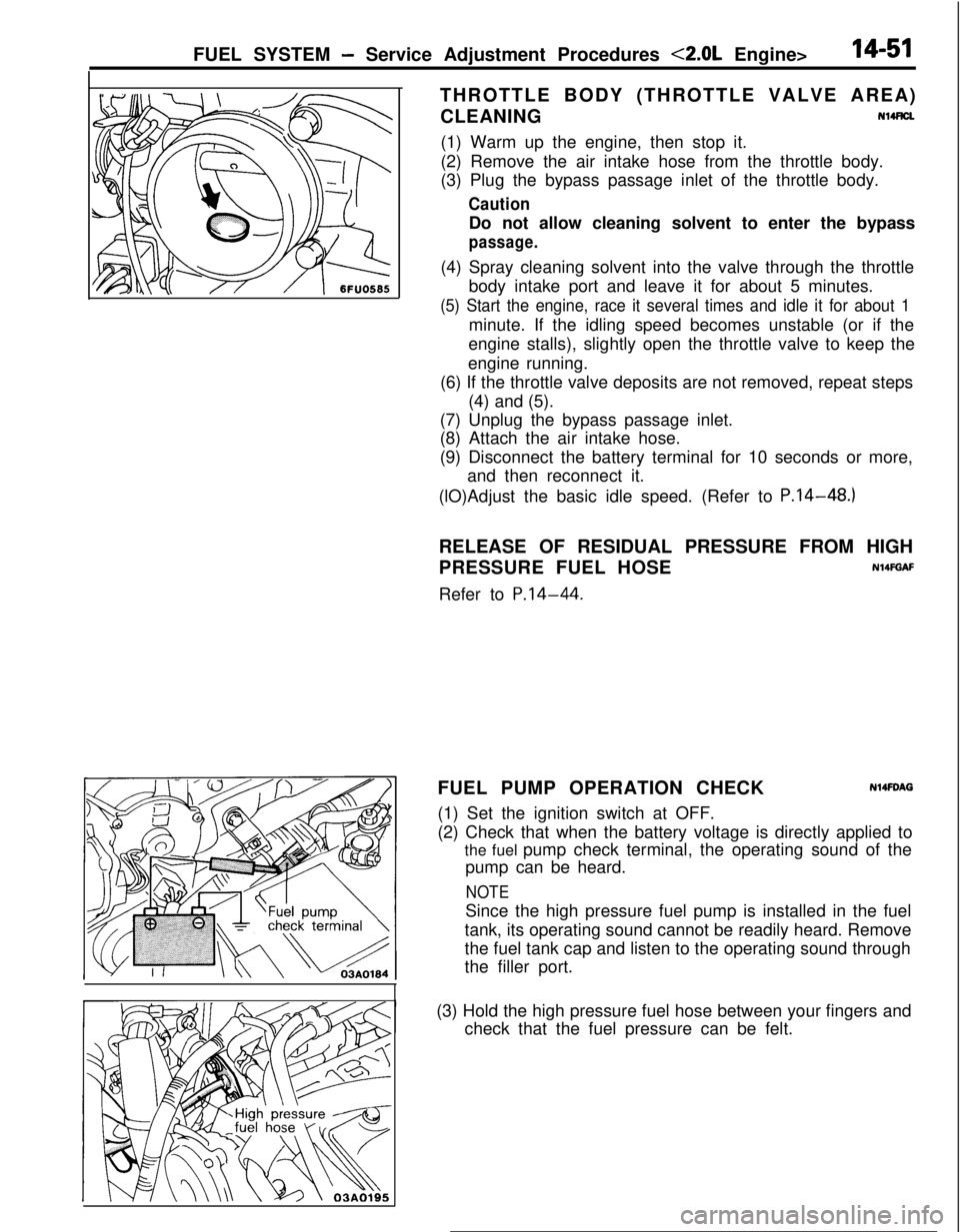
(1) Warm up the engine, then stop it.
(2) Remove the air intake hose from the throttle body.
(3) Plug the bypass passage inlet of the throttle body.
CautionDo not allow cleaning solvent to enter the bypass
passage.(4) Spray cleaning solvent into the valve through the throttle
body intake port and leave it for about 5 minutes.
(5) Start the engine, race it several times and idle it for about 1minute. If the idling speed becomes unstable (or if the
engine stalls), slightly open the throttle valve to keep the
engine running.
(6) If the throttle valve deposits are not removed, repeat steps
(4) and (5).
(7) Unplug the bypass passage inlet.
(8) Attach the air intake hose.
(9) Disconnect the battery terminal for 10 seconds or more,
and then reconnect it.
(lO)Adjust the basic idle speed. (Refer to P.14-48.)
RELEASE OF RESIDUAL PRESSURE FROM HIGH
PRESSURE FUEL HOSE
N14FGAFRefer to
P.14-44.FUEL PUMP OPERATION CHECK
N14FDAG(1) Set the ignition switch at OFF.
(2) Check that when the battery voltage is directly applied to
the fuel pump check terminal, the operating sound of the
pump can be heard.
NOTESince the high pressure fuel pump is installed in the fuel
tank, its operating sound cannot be readily heard. Remove
the fuel tank cap and listen to the operating sound through
the filler port.
I(3) Hold the high pressure fuel hose between your fingers and
check that the fuel pressure can be felt.
Page 510 of 1216

IL SYSTEM -MPI Svstem InsDection 4.8L Enaine>14-56FUE- _ ~-~~~~~ ~~ ~,~.
MPI SYSTEM INSPECTION <1.8L Engine>COMPONENTS
LncAT’n”’Ignition timing adjustment terminal
Fuel
ourno check terminal
Nl4PAAMAir-flow sensor
Intake air temperature sensor
Barometric pressuresensorCoolant temperature
sensornhibitor switch (A/T)
Inhibitor switch
-xT==-TL--==- IOlAO422
/Pxygen sensor
Page 512 of 1216

14-58FUEL SYSTEM -MPI System Inspection <1.8L Engine>
MALFUNCTION INDICATOR LIGHTNWQAB
Among the self-diagnosis items, a malfunction indicator light
comes on to notify the driver of the emission control items
when an irregularity is detected.
However, when an irregular signal returns to
notmal ‘and the
engine control unit judges that it has returned to normal, the
malfunction indicator light goes out.
Moreover, when the ignition switch is turned off, the light goes
out. Even if the ignition switch is turned on again, the light doesnot come on until the irregularity is detected.
Here, immediately after the ignition switch is turn on, the
malfunction indicator light is lit for 5 seconds to indicate that
the malfunction indicator light operates normally.
Items indicated by the lightening malfunction light
Engine control unit
Oxygen sensor
Air-flow sensor
Intake air temperature sensor
Throttle position sensor
Motor position sensor
Engine coolant temperature sensor
Crank angle sensor
No. 1 cylinder TDC sensor
Barometric pressure sensor
Ignition timing adjustment signal
Injector
Fuel pump
EGR system
The malfunction indicator light lights up when the ignition
timing adjustment terminal is short-circuited
,‘t’o ground.
Consequently, it lights up ,when the ignition timing
adjustment is grounded when adjusting ignition timing,
but in this case there is no abnormality.
MALFUNCTION INDICATOR LIGHT INSPECTlON
When turning on the ignition switch, check that the light comes
on.
NOTElf the light does not come on, check the harness and light for
breakage.SELF-DIAGNOSIS
Nl4PMFaThe engine control unit monitors the input/output signals
(some signals at all times and the others under specified
conditions) of the engine control unit.
Page 513 of 1216

FUEL SYSTEM - MPI System inspection <1.8L Engine>14-59
--..When it is noticed that an irregularity has continued for a
specified time or longer from when the irregular signal is
initially monitored. Passing a certain number, the engine
control unit judges that an irregularity has occurred, memorizesthe malfunction code, and outputs the signal to the
self-diagnosis output terminal.
There are 14 diagnosis items, and the diagnosis results can beread out with a voltmeter.
Moreover, since memorization of the malfunction codes is
backed up directly by the battery, the diagnosis results are
memorized even if the ignition key is turned off. The malfunc-
tion codes will, however, be erased when the battery terminal
or the engine control unit connector is disconnected.
Caution
If the sensor connector is disconnected with the ignition
switch turned on, the malfunction code is memorized. In
this case, disconnect the battery terminal’
(-) for 10seconds or more, and the diagnosis memory will be
erased.The 14 diagnosis items are provided as follows, and if plural
items are activated, they are all indicated sequentially from thesmallest code number.
perature sensor
CautionFor the malfunction code of the ignition timing adjustment
signal, the light for the ignition timing adjustment terminal
lights up when short-circuited to ground.
Consequently, it is output when the ignition timing
adjustment is grounded when adjusting ignition timing,
but in this case there is not abnormality.
CHECK PROCEDURE (SELF-DIAGNOSIS)N14PCAElPrecautions for Operation
(1) When battery voltage is low, no detection of failure is
possible. Be sure to check the battery for voltage and otherconditions before starting the test.
(2) Diagnosis item is erased if the battery or the engine controlunit connector is disconnected. Do not disconnect the
battery before the diagnosis result is completely read.
(3) After check and correction are over, disconnect ground
cable for
10 seconds or more from negative terminal of
battery and connect it again to make sure that failure code
is erased.
Page 514 of 1216

14-60FUEL SYSTEM - MPI Svstem lnwection <1.8L Engine>
7 MPI
diagnosis
LGround
DIAGNOSIS CHART (FAULT TREE)output
preference
orderDiagnosis item
1Engrne control
unit
2 2Oxygen sensor Oxygen sensor
3 3Air flow sensor Air flow sensor
4 4Intake air Intake airtemperature sensor temperature sensor
5 5Throttle position Throttle positionsensor sensor
6 6Motor position Motor positionsensor sensor
INSPECTION PROCEDURE - USING VOLTMETERN14PCAGl
(1) Connect an analogue voltmeter to the self-diagnosis con-,z
nectar.
‘~(2) Turn ignition switch to ON, and indication of engine control
unit memory contents will immediately start. If the system
is in normal condition, pointer of voltmeter indicates normalpattern. If any abnormality is in memory, the pointer of
voltmeter will deflect, indicating abnormal item as de-
scribed in “Diagnosis Chart”.
After recording the abnormal item, check and repair each
part according to the check items in “Diagnosis Chart”.
(3) If the defective parts have been repaired, disconnect the
negative terminal of battery cable for
10 seconds or more
and connect it again to make sure that the abnormal code
has been erased.
N14PRACDiagnosis code
Output signal pattern
:1
12A0104
12A0104
12A0104
12A0104
:JJlJJ--
12A0104
LII
12A0104
No.
-
11Retained
12Retained
14
15MemoryCheck item (Remedy)
-(ll#ace engine control
l Harness and connectorl Fuel, pressurel Injectors
(Replace if defective)
l Intake air leaks0 Oxygen sensor
l Harness and connector
(If harness and connector
are normal, replace airflow sensor assembly.)
Page 515 of 1216

FUEL SYSTEM - MPI System Inspection <1.8L Engine>
outputDiagnosis code
referenceDiagnosis itemCheck item (Remedy)
orderOutput signal patternNo.Memory
7Engine coolantRetainedl Harness and connectortemperature sensor
:-rlrLn- 2’
l Engine coolant temper-
ature sensor
12A0107
8Crank angle sensor
:nn 22
Retainedl Harness and connector
(If harness and connector
are normal, replacedistributor assembly.)
12A0107
9No. 1 cylinder top
dead center sensorH
Lnn 23
Retainedl Harness and connector
(If harness and connector
are normal, replacedistributor assembly.)
12A0107
10Vehicle speed sensor24Retainedl Harness and connector
(reed switch)H
Lu 1 nnJln
l Vehicle speed sensor
(reed switch)
12A0107
11Barometric pressure25Retainedl Harness and connector
sensorH
u I nl-uvln
(If harness and connector
are normal, replace
Lbarometric pressure
12A0107sensor assembly.)
12Ignition timing adjust-36-l Harness and connectorment signalH
LUUI nluvuuL
12R0468
13Injector
:m 41
Retainedl Harness and connector0 Injector coil resistance
12A0105
14Fuel pump42Retainedl Harness and connectorH0 Control relay
LUUUI nn
12A0105
15EGR
H
u u u u-inn
l EGRvalvel EGR valve control sole-Lnoid valve
12A0105l EGR valve control vacuurr
16Normal state---H
Ln
12A0104
NOTEReplace the engine control unit if a malfunction code is output although the inspection reveals that there is no problem with the check
items.