1991 MITSUBISHI 3000GT clock
[x] Cancel search: clockPage 1048 of 1146
52B-38 SUPPLEMENTAL RESTRAINT SYSTEM (SRS) - Troubleshooting
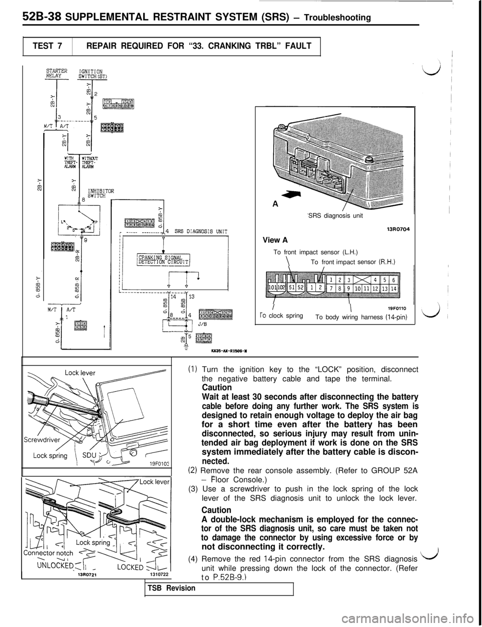
TEST 7REPAIR REQUIRED FOR “33. CRANKING TRBL” FAULT1
STARTERHULAYIGNITIONSWITCH(ST>
7%INHIBITOR
10SWITCH
FI
pkEE&r -...__ -_-_-___I4SRS DIAGNOSIS UNITI
I---..-___________ - ____
2
14 13
!z
CLYL
da d4--__J/S
-A) @g
:6x36-NC-R1606-USRS diagnosis unit
13R0704View A
To front impact sensor (L.H.)
\To frontimpactsensor (R.H.)
II19FOllOTo clock spring
To body wiring harness (14-pin)
(I) Turn the ignition key to the “LOCK” position, disconnect
the negative battery cable and tape the terminal.
Caution
Wait at least 30 seconds after disconnecting the battery
cable before doing any further work. The SRS system is
designed to retain enough voltage to deploy the air bagfor a short time even after the battery has been
disconnected, so serious injury may result from unin-
tended air bag deployment if work is done on the SRSsystem immediately after the battery cable is discon-
nected.
(2) Remove the rear console assembly. (Refer to GROUP 52A-.
13R07211310722
- Floor Console.)
(3) Use a screwdriver to push in the lock spring of the lock
lever of the SRS diagnosis unit to unlock the lock lever.
Caution
A double-lock mechanism is employed for the connec-
tor of the SRS diagnosis unit, so care must be taken not
to damage the connector by using excessive force or bynot disconnecting it correctly.
(4) Remove the red
14-pin connector from the SRS diagnosis
unit while pressing down the lock of the connector. (Refer
to
P52B-9.1
I/’
TSB Revision
Page 1055 of 1146
SUPPLEMENTAL RESTRAINT SYSTEM (SRS) - Troubleshooting 52B-45
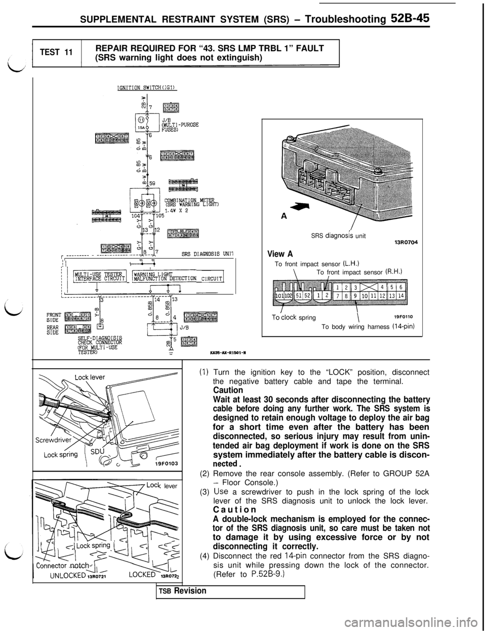
TEST 11REPAIR REQUIRED FOR “43. SRS LMP TRBL 1” FAULT
(SRS warning light does not extinguish)
IGNITION SWITCH(IG1)
COMBINATION METER(SRS WARNING LIGHT)1.4w x 2
r _________ - ____..__-----SRS DIAGNOSIS UN11I" n
/ 1 -1 "fT%~~ION CIRCUIT/
SELF-DIAGNOISISCHECK CONNECTOR(TFEOSRTOF.h~ll-USE=Kx35-Ax-RIY)I-I
SRS diagno&unit13R0704
View ATo front impact sensor (L.H.)
\To front impact sensor (R.H.1
To’clock spring\19FOllO
To body wiring harness (14-pin)
< lever
I 7’1,~,JLockspring (
2
(1) Turn the ignition key to the “LOCK” position, disconnect
the negative battery cable and tape the terminal.
Caution
Wait at least 30 seconds after disconnecting the battery
cable before doing any further work. The SRS system is
designed to retain enough voltage to deploy the air bagfor a short time even after the battery has been
disconnected, so serious injury may result from unin-
tended air bag deployment if work is done on the SRSsystem immediately after the battery cable is discon-
netted .(2) Remove the rear console assembly. (Refer to GROUP 52A
Floor Console.)
(3) Use a screwdriver to push in the lock spring of the lock
lever of the SRS diagnosis unit to unlock the lock lever.
Caution
A double-lock mechanism is employed for the connec-
tor of the SRS diagnosis unit, so care must be taken notto damage it by using excessive force or by not
disconnecting it correctly.(4) Disconnect the red
16pin connector from the SRS diagno-
sis unit while pressing down the lock of the connector.
(Refer to
P.52B-9.)
TSB Revision
Page 1061 of 1146
SRS Maintenance and
SUPPLEMENTAL RESTRAINT SYSTEM (SRS) - Post-coltision Diagnosis 52B-51
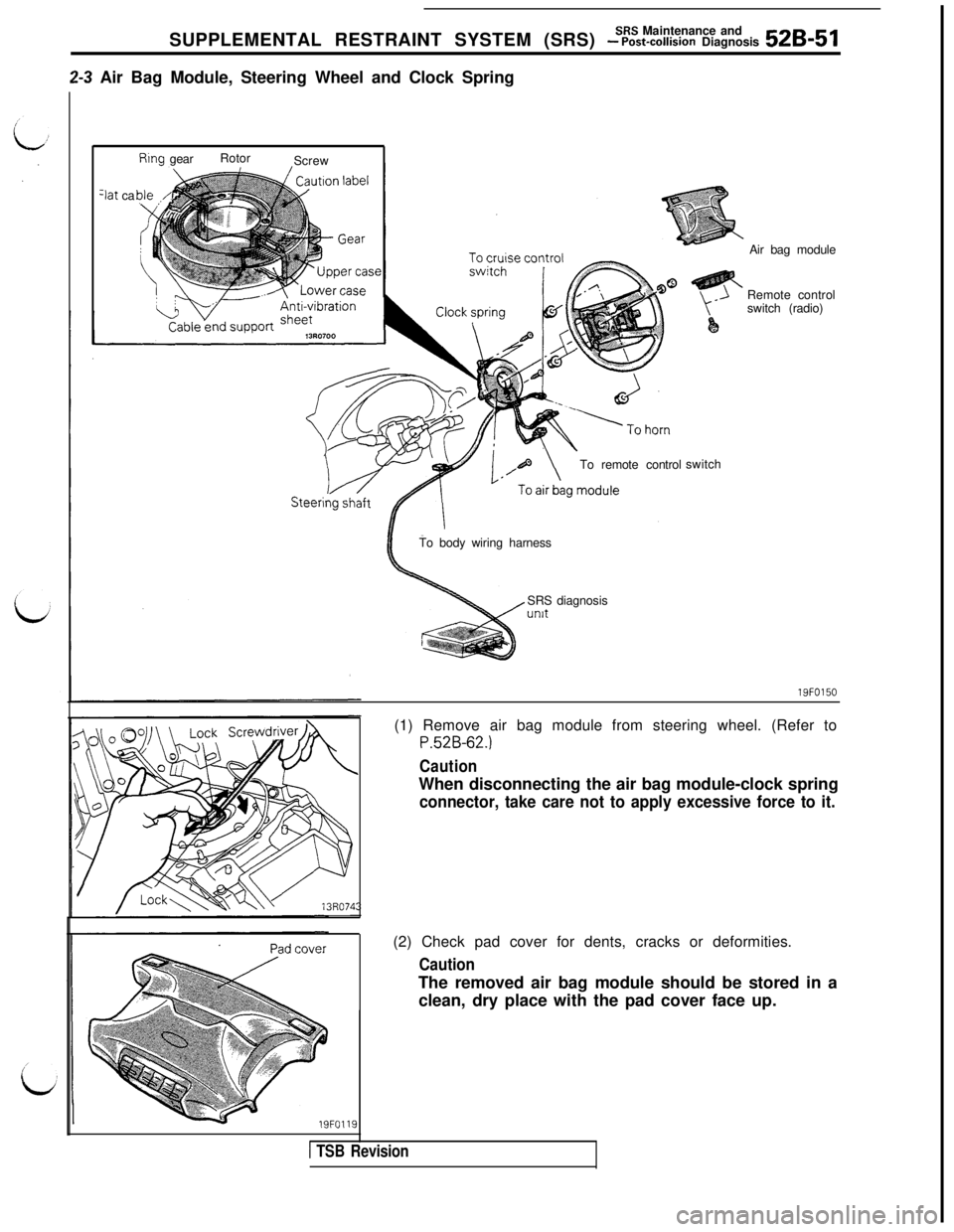
2-3 Air Bag Module, Steering Wheel and Clock Spring
Rtng gearRotor
Screw
3at ca
To remote controlswitchAir bag module
Remote control
switch (radio)
To body wiring harness
SRS diagnosisunit
19FO150
19FO119(1) Remove air bag module from steering wheel. (Refer to
P.52B-62.)
CautionWhen disconnecting the air bag module-clock spring
connector, take care not to apply excessive force to it.(2) Check pad cover for dents, cracks or deformities.
CautionThe removed air bag module should be stored in a
clean, dry place with the pad cover face up.
1 TSB Revision
Page 1062 of 1146
52B-52 SUPPLEMENTAL RESTRAINT SYSTEM fSRSI - ~Z-%~~~~aK&%kTo air bagmodule
To SRS dragnosls unit
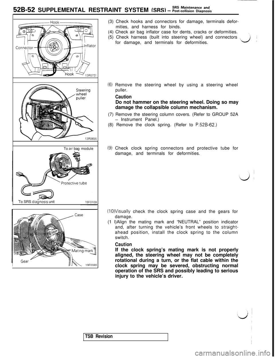
I19FOO89(3) Check hooks and connectors for damage, terminals defor-
mities, and harness for binds.
(4) Check air bag inflator case for dents, cracks or deformities.
\(5) Check harness (built into steering wheel) and connectors
~for damage, and terminals for deformities.LA
(6) Remove the steering wheel by using a steering wheel
puller.
CautionDo not hammer on the steering wheel. Doing so may
damage the collapsible column mechanism.
(7) Remove the steering column covers. (Refer to GROUP 52A
- Instrument Panel.)
(8) Remove the clock spring. (Refer to
P.52B-62.)
(9) Check clock spring connectors and protective tube for
damage, and terminals for deformities.
(10)Visually check the clock spring case and the gears for
damage.(1 l)Align the mating mark and “NEUTRAL” position indicator
and, after turning the vehicle’s front wheels to straight-
ahead position, install the clock spring to the column
switch.
CautionIf the clock spring’s mating mark is not properly
aligned, the steering wheel may not be completely
rotational during a turn, or the flat cable within the
clock spring may be severed, obstructing normal
operation of the SRS and possibly leading to serious
injury to the vehicle’s driver.
TSB Revision
Page 1065 of 1146
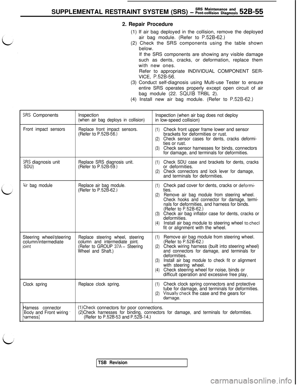
SUPPLEMENTAL RESTRAINT SYSTEM (SRS) - ~~~-~~~~~a~~g~~~s 52B-552. Repair Procedure
(1) If air bag deployed in the collision, remove the deployed
air bag module. (Refer to
P.52B-62.)(2) Check the SRS components using the table shown
below.
If the SRS components are showing any visible damage
such as dents, cracks, or deformation, replace them
with new ones.
Refer to appropriate INDIVIDUAL COMPONENT SER-
VICE, P.52B-56.
(3) Conduct self-diagnosis using Multi-use Tester to ensure
entire SRS operates properly except open circuit of air
bag module (22. SQUIB TRBL 2).
(4) Install new air bag module. (Refer to
P.52B-62.)
SRS ComponentsInspection(when air bag deploys in collision)Inspection (when air bag does not deploy
in low-speed collision)
Front impact sensors
Replace front impact sensors.(Refer to P.52B-56.)(1)Check front upper frame lower and sensor
brackets for deformities or rust.
(2)Check sensor cases for dents, cracks deformi-ties or rust.
(3)Check sensor harnesses for binds, connectors
for damage, and terminals for deformities.
SRS diagnosis unitSDU)Replace SRS diagnosis unit.(Refer to P.52B-59.)(1)Check SDU case and brackets for dents, cracksor deformities.(2)Check connectors and lock lever for damage,and terminals for deformities.
jir bag moduleReplace air bag module.(Refer to P.52B-62.)(1)Check pad cover for dents, cracks or deformi-ties.
(2)Remove air bag module from steering wheel.
Check hooks and connector for damage, termi-
nals for deformities, and harness for binds.
(Refer to P.52B-62.)(3)Check air bag inflator case for dents, cracks or
deformities.
(4)Install air bag module to steering wheel to.checlfit or alignment with the wheel.
Steering wheel/steering
(1)column/intermediateReplace steering wheel, steering
iointcolumn and intermediate joint.Remove air bag module from steering wheel.
(Refer to P.52B-62.)(Refer to GROUP 37A- Steering(2)Wheel and Shaft.)Check wiring harness (built into steering wheel)and connectors for damage, and terminals fordeformities.(3)Install air bag module to check fit or alignmentwith steering wheel.(4)Check steering wheel for noise, binds or
difficult operation and excessive free play,
Clock springReplace clock spring.(1)Check clock spring connectors and protective
tube for damage, and terminals for deformities.
(2)&/;yecheck the case and the gears for
Harness connectorIBody and Front wiring ’(1 )Check connectors for poor connections.
iarnessl(2)Check harnesses for binding, connectors for damage, and terminals for deformities.(Refer to P.52B-53 and P.52B-14.)
TSB Revision
Page 1066 of 1146
52B-56SUPPLEMENTAL RESTRAINT SYSTEM (SRS) - front lwtact sensors
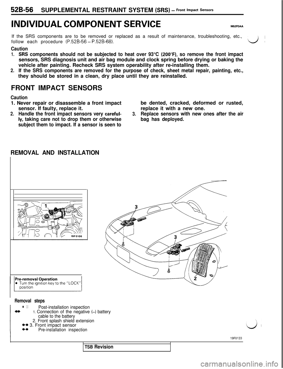
INDIVIDUAL COMPONENT SERVICEIf the SRS components are to be removed or replaced as a result of maintenance, troubleshooting, etc.,
follow each procedure
(P.52B-56 - P.52B-68).L++(
Caution
1.SW components should not be subjected to heat over 93°C (2OO”F), so remove the front impactsensors, SRS diagnosis unit and air bag module and clock spring before drying or baking the
vehicle after painting. Recheck SRS system operability after re-installing them.
2.If the SRS components are removed for the purpose of check, sheet metal repair, painting, etc.,they should be stored in a clean, dry place until they are reinstalled.
FRONT IMPACT SENSORS
Caution1. Never repair or disassemble a front impact
sensor. If faulty, replace it.
2.Handle the front impact sensors very careful-
ly, taking care not to drop them or otherwise
subject them to impact. If a sensor is seen tobe dented, cracked, deformed or rusted,
replace it with a new one.
3.Replace sensors with new ones after the air
bag has deployed.
REMOVAL AND INSTALLATION
Removal steps
l *Post-installation inspectiona*1. Connection of the negative (-) battery
cable to the battery
2. Front splash shield extension
I)* 3. Front impact sensorI)*Pre-installation inspection
I19FO133
TSB Revision
Page 1069 of 1146
SUPPLEMENTAL RESTRAINT SYSTEM (SRS)- SRS Diagnosis Unit (SDU) 52B-59
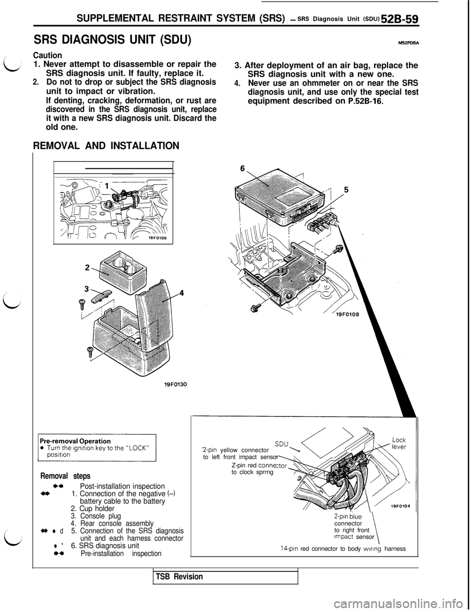
SRS DIAGNOSIS UNIT (SDU)M52PDBA
Caution1. Never attempt to disassemble or repair the
SRS diagnosis unit. If faulty, replace it.
2.Do not to drop or subject the SRS diagnosisunit to impact or vibration.
If denting, cracking, deformation, or rust are
discovered in the SRS diagnosis unit, replace
it with a new SRS diagnosis unit. Discard theold one.3. After deployment of an air bag, replace the
SRS diagnosis unit with a new one.
4.Never use an ohmmeter on or near the SRS
diagnosis unit, and use only the special testequipment described on
P.!i2B-16.
REMOVAL AND INSTALLATION
Removal steps
*aPost-installation inspectionaI)1. Connection of the negative
battery cable to the battery
2. Cup holder
19FO130
t-1
3. Console plug
4. Rear console assembly
a* l d5. Connection of the SRS diagnosis
unit and each harness connector
l *6. SRS diagnosis unit*cPre-installation inspection
2-pin yellow connector
to left front impact sensor
Z-pin red
tonneto clock sprrng
Z-pin dlueconnector
to right front
\Impact sensor14-pin red connector to body wlnng harness
TSB Revision
Page 1070 of 1146
52B-60 SUPPLEMENTAL RESTRAINT SYSTEM (SRS) - SRS Diagnosis Unit (SW
0I/-Battery e
13R0721lSF1072:
SRS diagnosis unitView A13R0704
To front impact sensor
(L.H.)
\To front impact sensor (R.H.1\I
I- - -,I1
\To clock springTo body wiring harness (14-pin)19FOllt
r-TSB I
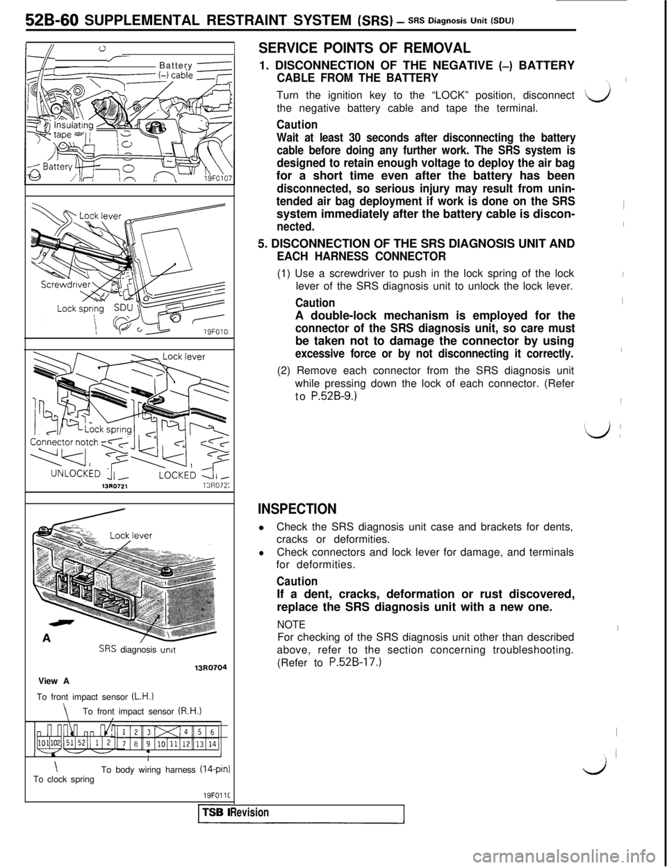
SERVICE POINTS OF REMOVAL1. DISCONNECTION OF THE NEGATIVE
(-) BATTERY
CABLE FROM THE BATTERYTurn the ignition key to the “LOCK” position, disconnect
the negative battery cable and tape the terminal.
Caution
Wait at least 30 seconds after disconnecting the battery
cable before doing any further work. The SRS system is
designed to retain enough voltage to deploy the air bagfor a short time even after the battery has been
disconnected, so serious injury may result from unin-
tended air bag deployment if work is done on the SRSsystem immediately after the battery cable is discon-
nected.5. DISCONNECTION OF THE SRS DIAGNOSIS UNIT AND
EACH HARNESS CONNECTOR(1) Use a screwdriver to push in the lock spring of the lock
lever of the SRS diagnosis unit to unlock the lock lever.
CautionA double-lock mechanism is employed for the
connector of the SRS diagnosis unit, so care mustbe taken not to damage the connector by using
excessive force or by not disconnecting it correctly.(2) Remove each connector from the SRS diagnosis unit
while pressing down the lock of each connector. (Refer
to
P.52B-9.)
INSPECTIONlCheck the SRS diagnosis unit case and brackets for dents,
cracks or deformities.
lCheck connectors and lock lever for damage, and terminals
for deformities.
CautionIf a dent, cracks, deformation or rust discovered,
replace the SRS diagnosis unit with a new one.
NOTEFor checking of the SRS diagnosis unit other than described
above, refer to the section concerning troubleshooting.
(Refer to
P.52B-17.)
Revision
\\I
‘d
I
I
I1
I~
\Lj (
I
I
~ I
kJ