Page 1016 of 1146
52B-6SUPPLEMENTAL RESTRAINT SYSTEM (SRS) - General Information
;RS SCHEMATIC
STARTER RELAYIGNITION SWITCH MIT
I
‘dIGNITION SWITCH
IMulti
-purpose fuses
Connector
lock switch
----
r
1
UNLOCKiM/T -AA
IWarning light
malfunction
detection circuitICrank signal detection circuit
Connector lock
detection circuit
Safing
impact
sensor
1
N
i-Multi-use ,
Tester
interface
circuit
Self-diagnosis
check connector
(For Multi-use
Tester)
19FO141Front impact
sensor
(L.H.)Clock spring
Front impact
sensor (R.H.)IP-l-Air bag
module
TSB Revision
Page 1018 of 1146
52B-8SUPPLEMENTAL RESTRAINT SYSTEM (SRS) - General Information
36FOOOlJ/C-57 Clock spring
C-59 Ignition switch
C-79 Self-diagnosis check
connector (For
Multi-use Tester)
IbJInstrument panel and floor console
D-
D-03
D-04Combination meter
D-05
D-2314-pin red connector
to body wiring harness
D-24Z-pin blue connector to
right front impact sensor
D-252-pin yellow connector to
left front impact sensor
D-262-pin red connector to
clock springConnector to
SRS Diagnosis
UnitD-26225
TSB Revision,1
Page 1020 of 1146

52B-10SUPPLEMENTAL RESTRAINT SYSTEM (SRS) - General InformationI
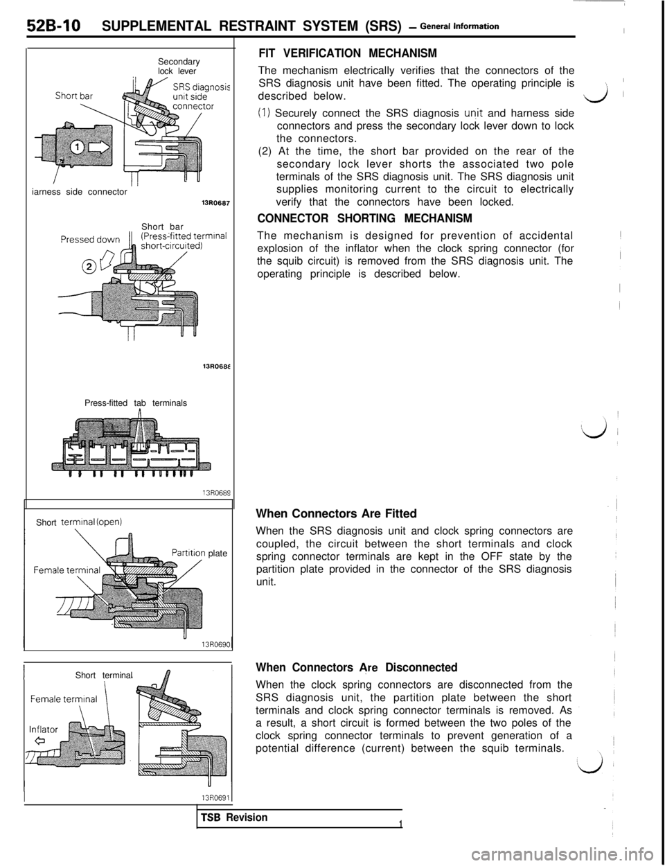
FIT VERIFICATION MECHANISMSecondary
lock leverThe mechanism electrically verifies that the connectors of the
SRS diagnosis unit have been fitted. The operating principle is
:described below.
d
(
(1) Securely connect the SRS diagnosis un.it and harness side
connectors and press the secondary lock lever down to lock
the connectors.
sisiarness side connector
13R0687Short bar
nlnal13R068E
Press-fitted tab terminals
13R0689Short
terminal (open)
plate
IShort terminal
I13R06911(2) At the time, the short bar provided on the rear of the
secondary lock lever shorts the associated two pole
terminals of the SRS diagnosis unit. The SRS diagnosis unit
supplies monitoring current to the circuit to electrically
verify that the connectors have been locked.
CONNECTOR SHORTING MECHANISMThe mechanism is designed for prevention of accidental
explosion of the inflator when the clock spring connector (for
the squib circuit) is removed from the SRS diagnosis unit. The
operating principle is described below.
When Connectors Are Fitted
When the SRS diagnosis unit and clock spring connectors are
coupled, the circuit between the short terminals and clock
spring connector terminals are kept in the OFF state by the
partition plate provided in the connector of the SRS diagnosis
unit.
When Connectors &e DisconnectedWhen the clock spring connectors are disconnected from the
SRS diagnosis unit, the partition plate between the short
terminals and clock spring connector terminals is removed. As
a result, a short circuit is formed between the two poles of the
clock spring connector terminals to prevent generation of a
potential difference (current) between the squib terminals.
TSB Revision1
Page 1022 of 1146
52B-12SUPPLEMENTAL RESTRAINT SYSTEM (SRS) -General Information
CAUTION1.DO not repair, splice or modify SRS wiring (except for specific repairs to the body wiring harness shown on page QB-14
2.replace wiring if necessary, after reading and following all precautions and procedures in this manual.DO not use an analogue ohmmeter to check SRS wiring or components; use only special tools and digital multi-metershown on page 52B-16.
12B-W2B-W
,, 7
B-WI\.J/B0(MULTI-PURPOSEFUSES)
10A
0.85B-WI' 2
---_-__--_----_--------~---~~~--~~--~~-~-~----~---- --_5SRS DIAGNOSIS UNIT
= CONSTANT4I- -xI
> VOLTAGE CIRCUITCONDENSIDETECTIL,. vAI\vvII ,
vvvn ,n N~,11rrnm,vn
Ttttlr .,,,,,,a
l@i fTii51 l@!l %piJ’
/
-i----
EBI
102!x 101
‘o’ @ii?r
i 1I
z
dd
3) clEl $1BVIi2VI
Qy y2 qli y jl y2/
FRONTIMPACTFRONT ' - ' '
SENSOR
I!?--
IMPACT
SENSOR
(L.H.)OFF -If-(R. H. )II
CLOCKSPRING
(5QUIBjAIR QA$e_MODULE
TSB Revision
Page 1024 of 1146

.52B-14 SUPPLEMENTAL RESTRAINT SYSTEM (SRS) - SRS Service Precautions
SRS SERVICE PRECAUTIONSMBZPBAA
1.In order to avoid injury to yourself or others from3.accidental deployment of the air bag during SRSNever Attempt to Repair the Following Com-servicing, read and carefully follow all the
pre-
ponents:dcautions and procedures described in this
manu-l Front Impact Sensors
al.l SRS Diagnosis Unit (SDU)
2.Do not use any electrical test equipment on orl Clock Spring
near SRS components, except those specifiedl Air Bag Module
on
P.52B-16.If any of those components are diagnosed as
Never use an analogue ohmmeter.faulty, they should only be replaced, in accord-
ance with the INDIVIDUAL COMPONENT SER-
VICE procedures in this manual, starting at page
[52B-561.
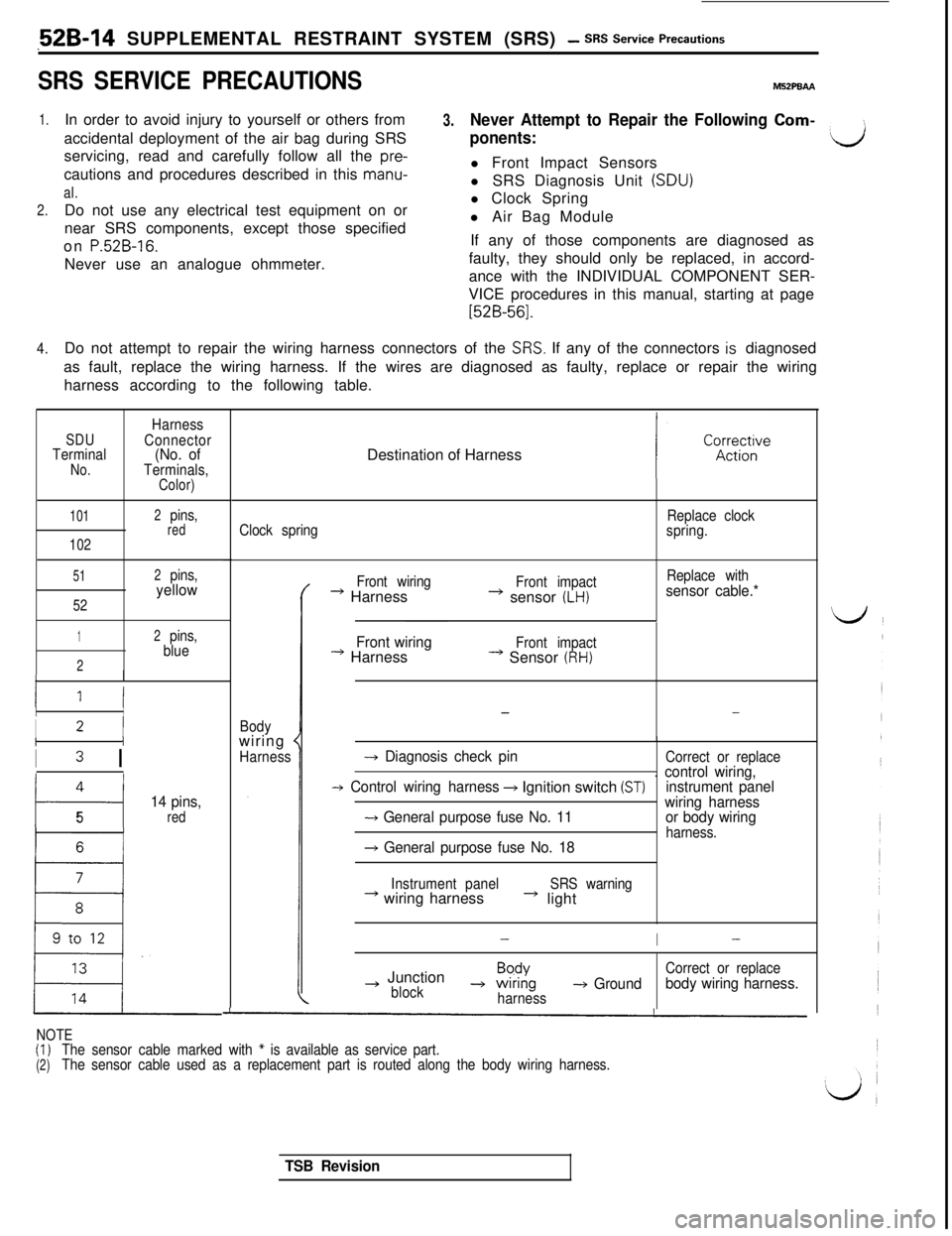
4.Do not attempt to repair the wiring harness connectors of the
SRS. If any of the connectors is diagnosed
as fault, replace the wiring harness. If the wires are diagnosed as faulty, replace or repair the wiring
harness according to the following table.
SDUTerminalNo.
Harness
Connector
(No. ofTerminals,Color)
101
102
2pins,red
51
52
2pins,yellow
12pins,
blue
2
II
II
I2 IIi
I3 I
4
t---i
14 pins,
5red
16 t
LDestination of Harness
Clock springReplace clock
spring.
Bodywiring
*
HarnessFront wiring
* HarnessFront impact+ sensor (LH)
Replace withsensor cable.*
Front wiring
--) HarnessFront impact* Sensor (RH)
--
-+ Diagnosis check pinCorrect or replace
-+ Control wiring harness+ Ignition switch (ST). control wiring,
instrument panel
-+ General purpose fuse No. 11wiring harness
or body wiringharness.+ General purpose fuse No. 18
Instrument panel+ wiring harnessSRS warning* light
-I-
~ JunctionBpdYCorrect or replace
block-+ wrnng-+ Groundharnessbody wiring harness.
NOTE(I)
(2)The sensor cable marked with * is available as service part.
The sensor cable used as a replacement part is routed along the body wiring harness.
TSB Revision
Page 1025 of 1146

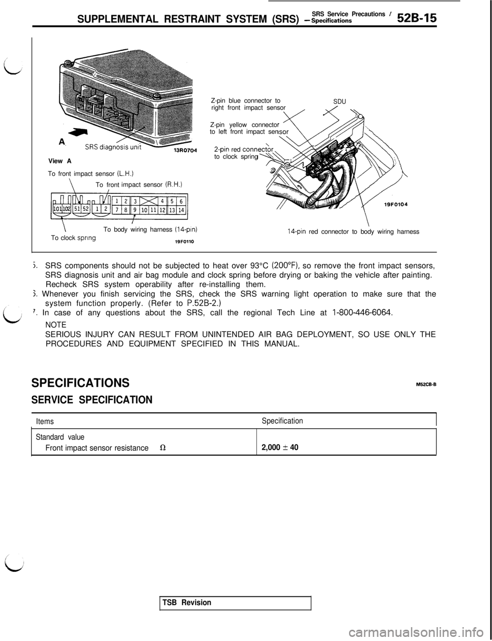
SRS ServicePrecautions /SUPPLEMENTAL RESTRAINT SYSTEM (SRS) - Spectiications52B-15View A
To front impact sensor
(L.H.)
\To frontimpactsensor (R.H.)
\To body wiring harness (14-pin)To clock spring19FOllOZ-pin blue connector to
right front impact sensor
Z-pin yellow connector
to left front impact sen2-pin red corm
to clock spring
SDU
14-pin red connector to body wiring harness
j.SRS components should not be subjected to heat over 93°C (2OO”F), so remove the front impact sensors,
SRS diagnosis unit and air bag module and clock spring before drying or baking the vehicle after painting.
Recheck SRS system operability after re-installing them.
j. Whenever you finish servicing the SRS, check the SRS warning light operation to make sure that the
system function properly. (Refer to
P.52B-2.)
7. In case of any questions about the SRS, call the regional Tech Line at I-800-446-6064.
NOTESERIOUS INJURY CAN RESULT FROM UNINTENDED AIR BAG DEPLOYMENT, SO USE ONLY THE
PROCEDURES AND EQUIPMENT SPECIFIED IN THIS MANUAL.
SPECIFICATIONSMUCB-B
SERVICE SPECIFICATION
ItemsSpecification
Standard value
Front impact sensor resistanceQ2,000 f 40
TSB Revision
Page 1030 of 1146
![MITSUBISHI 3000GT 1991 Service Manual 52B-20 SUPPLEMENTAL RESTRAINT SYSTEM (SRS) - Troubleshooting
SELF-DIAGNOSIS QUICK REFERENCE CHART
Fault
No.
-
11
32
Diagnosis code name
[Failure mode]
(NORMAL)
G-SENS. TRBL
1[Short circuit]
G-SENS. T MITSUBISHI 3000GT 1991 Service Manual 52B-20 SUPPLEMENTAL RESTRAINT SYSTEM (SRS) - Troubleshooting
SELF-DIAGNOSIS QUICK REFERENCE CHART
Fault
No.
-
11
32
Diagnosis code name
[Failure mode]
(NORMAL)
G-SENS. TRBL
1[Short circuit]
G-SENS. T](/manual-img/19/57085/w960_57085-1029.png)
52B-20 SUPPLEMENTAL RESTRAINT SYSTEM (SRS) - Troubleshooting
SELF-DIAGNOSIS QUICK REFERENCE CHART
Fault
No.
-
11
32
Diagnosis code name
[Failure mode]
(NORMAL)
G-SENS. TRBL
1[Short circuit]
G-SENS. TRBL 2[One open-circuit]
G-SENS. TRBL 3[Two open-circuit]
SQUIB TRBL 1[Short circuit]
SQUIB TRBL 2
[Open-circuit]
CONDENS. VO. HI
CONDENS. VO. LO
CRANKING TRBL
CONN. UNLOCKED
Explanation
Normal. The SRS is in goodorder.
The circuits for the front impact sensor are shortedto each other.
Right or left impact sensor cirucit is open or the
wire from the sensor to the SDU is open-circuit.
Right and left impact sensor circuits are open or thewires from the sensors to the SDU areopen-circuit.
The circuits for the air bag module (squib) are
shorted to each other or the circuit isgrounded.
The air bag module Isquib) circuit is open or the wire
from the air bag to the SDU (clock spring) is open-circuit.
The capacitor (integrated in the
SDU) terminal voltage
is higher than the specified value for 5 seconds.
The capacitor (integrated in the
SDU) terminal voltage
is lower than the specified value for 5 seconds.
The circuit for the cranking signal is shorted to
some power supply circuits.
It takes at least 45 seconds that the SDU detects
this fault.
The lock switch (short bar) of the SDU double lockconnector isopen.Service
Perform TEST 5
Perform TEST 6(I) Turn the ignition key
to the “LOCK” posi-
tion, disconnect the
negative battery
cable and tape the
terminal.
(2) After waiting atleast 30 seconds,
replace the SDU.
(Refer to P.52B-59.)
Perform TEST 7
Perform TEST 8NOTE
- IMPORTANT
(1) After repairing the SRS, reconnect the battery cable, erase the diagnosis code memory from theMulti-use Tester and check the SRS warning light operation to verify the system functions
properly. (Refer to TEST 1.)
(2) SDU
= SRS Diagnosis Unit
1 TSB Revision
Page 1032 of 1146

52B-22 SUPPLEMENTAL RESTRAINT SYSTEM (SRS) - Troubleshooting
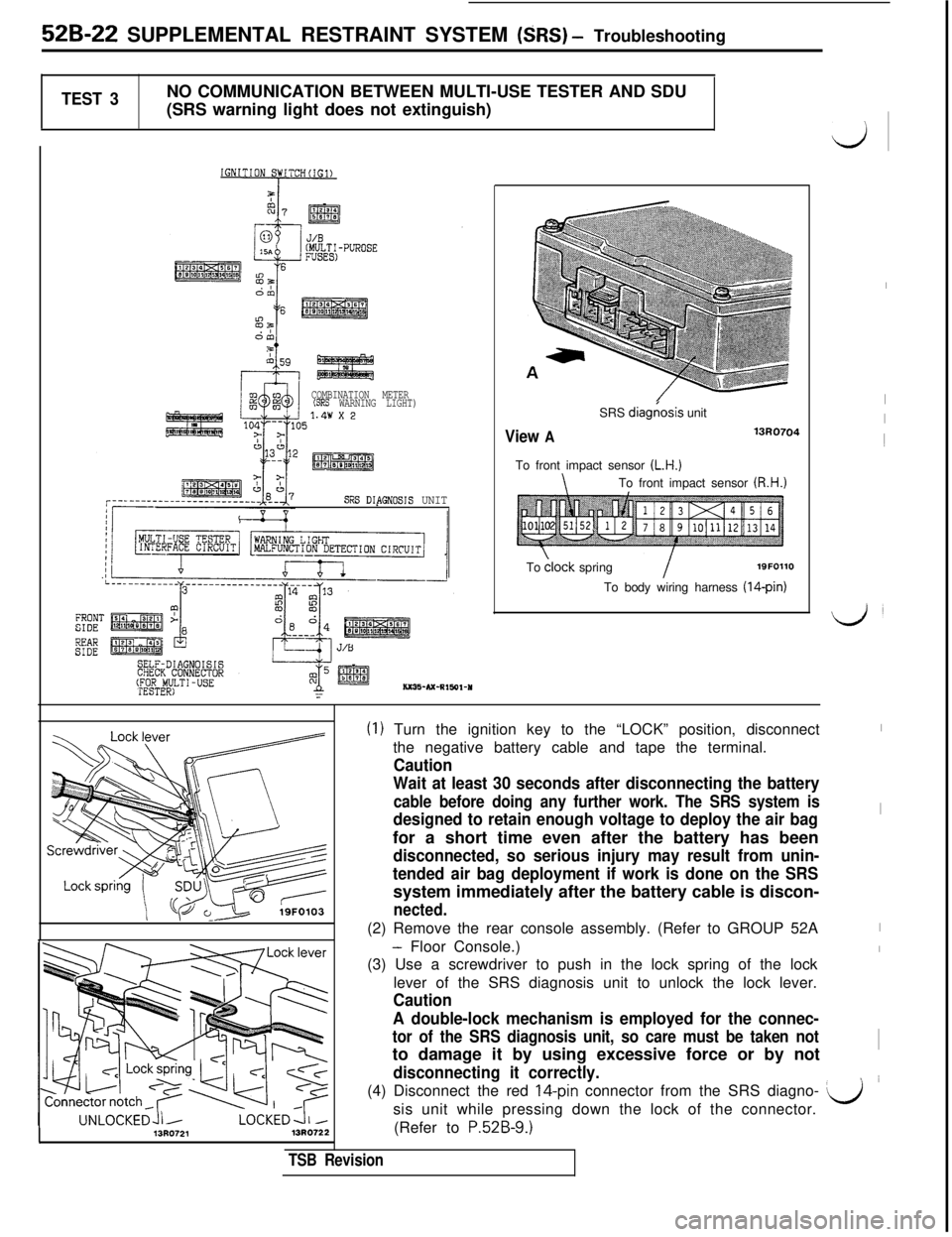
TEST 3NO COMMUNICATION BETWEEN MULTI-USE TESTER AND SDU
(SRS warning light does not extinguish)
COMBINATION METER(SRS WARNING LIGHT)
SRS DIPGNOSIS UNITSRS
diag(osis unit
View A13R0704To front impact sensor
(L.H.)
\To front impact sensor (R.H.)To
clock springI19FOllO
To body wiring harness (14-pin)
13R072113RO72:L
A double-lock mechanism is employed for the connec-
tor of the SRS diagnosis unit, so care must be taken notto damage it by using excessive force or by not
. .disconnecting it correctly.(4) Disconnect the red
IQpin connector from the SRS diagno- Q’sis unit while pressing down the lock of the connector.
(Refer to
P.52B-9.)
TSB Revision
(1) Turn the ignition key to the “LOCK” position, disconnect
the negative battery cable and tape the terminal.
Caution
Wait at least 30 seconds after disconnecting the battery
cable before doing any further work. The SRS system is
designed to retain enough voltage to deploy the air bagfor a short time even after the battery has been
disconnected, so serious injury may result from unin-
tended air bag deployment if work is done on the SRSsystem immediately after the battery cable is discon-
nected.(2) Remove the rear console assembly. (Refer to GROUP 52A
- Floor Console.)
(3) Use a screwdriver to push in the lock spring of the lock
lever of the SRS diagnosis unit to unlock the lock lever.
Caution
d
I
I
I1
LJ
I
I
I
I
I