1991 MITSUBISHI 3000GT clock
[x] Cancel search: clockPage 854 of 1146

37A-26
STEERING - Power Steerina Gear Box
Apply grease
Approx. 1 mm
l-(Approx. .040 in.)
Tool
13POO76
End plug
Sealant
13K130
’ IEnd plug
r=13K132
MB991 006-01
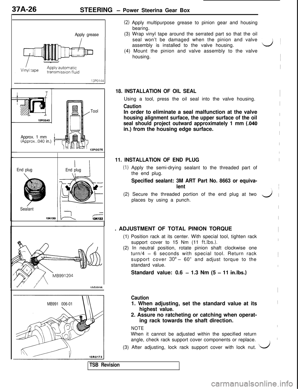
(2) Apply multipurpose grease to pinion gear and housing
bearing.(3) Wrap vinyl tape around the serrated part so that the oil
seal won’t be damaged when the pinion and valve
assembly is installed to the valve housing.
(4) Mount the pinion and valve assembly to the valve
housing.
18. INSTALLATION OF OIL SEALUsing a tool, press the oil seal into the valve housing.
CautionIn order to eliminate a seal malfunction at the valve
housing alignment surface, the upper surface of the oil
seal should project outward approximately 1 mm
(.040in.) from the housing edge surface.
11. INSTALLATION OF END PLUG
(1) Apply the semi-drying sealant to the threaded part of
the end plug.
Specified sealant: 3M ART Part No. 8663 or equiva-
lent(2) Secure the threaded portion of the end plug at two
places by using a punch.
. ADJUSTMENT OF TOTAL PINION TORQUE
(1) Position rack at its center. With special tool, tighten rack
support cover to 15 Nm (11
ft.lbs.1.(2) In neutral position, rotate pinion shaft clockwise one
turn/4
- 6 seconds with special tool. Return rack
support cover 30”
- 60” and adjust torque to the
standard value.
Standard value: 0.6
- 1.3 Nm (5 - 11 in.lbs.)
Caution1. When adjusting, set the standard value at its
highest value.2. Assure no ratcheting or catching when operat-
ing rack towards the shaft direction.
NOTEWhen it cannot be adjusted within the specified return
angle, check rack support cover components or replace.
ii1
I1
I
I
I
I1
I
I
I
I
yl (
I
I1
I1
I
I1
I
I\(3) After adjusting, lock rack support cover with lock nut.
i/
TSB Revision
Page 873 of 1146

42-1
BODY
CONTENTSM42AA- -
CENTER PILLAR GLASS........................................................32
CENTRAL DOOR LOCKING SYSTEM
................................55
DOOR ASSEMBLY....................................................................40
DOOR GLASS AND REGULATOR
........................................42
DOOR HANDLE AND LATCH
................................................54
DOOR TRIM AND WATERPROOF FILM
............................41
DRIP LINE WEATHERSTRIP....................................................65
ENGINE HOOD........................................................................18
FENDER*....................................................................................23
FUEL TANK FILLER DOOR
....................................................22
LIFTGATE....................................................................................20
LIFTGATE GLASS....................................................................37
LOOSE PANEL
........................................................................24
POWER WINDOW
....................................................................43
QUARTER WINDOW GLASS
................................................33SERVICE ADJUSTMENT PROCEDURES
............................
Door Adjustment................................................................Door inside Handle Play Check............................................Door Window Glass Adjustment........................................Floor Pan inspection............................................................Fuel Filler Door Adjustment................................................Hood Adjustment................................................................Liftgate Adjustment............................................................
SPECIAL TOOLS........................................................................
SPECIFICATIONS....................................................................
General Specifications........................................................Sealants and Adhesives........................................................
ServiceSpecifications........................................................
TROUBLESHOOTING............................................................
WINDOW GLASS....................................................................
WINDSHIELD............................................................................
13
14
16
14
17
14
13
13
4
2
2
3
3
5
25
28
SUPPLEMENTAL RESTRAINT SYSTEM (SRS)
(1)A Supplemental Restraint System (SRS), which uses a driver-side air bag, has been installed in the 3000GT.(2)The SRS includes the following components: impact sensors, SRS diagnosis unit: SRS warning light, air bagmodule, clock spring, interconnecting wiring. Other SRS-related components (that may have to be
removed/installed in connection with SRS service or maintenance) are indicated in the table of contents byan asterisk (*).
WARNING!(1)Improper service or maintenance of any component of the SRS, or any SRS-related component, can lead to
personal injury or death to service personnel (from inadvertent firing of the air bag) or to the driver (from
rendering the SRS inoperative).
(2) Service or maintenance of any SRS component or SRS-related component must be performed only at an
authorized MITSUBISHI dealer.(3) MITSUBISHI dealer personnel must thoroughly review this manual, and especially its GROUP 52B
-Supplemental Restraint System (SRS), before beginning any service or maintenance of any component of the
SRS or any SRS-related component.
Page 874 of 1146

42-2BODY - SDecifications
SPECIFICATIONS
GENERAL SPECIFICATIONS
M42CA. -
Items
Hood
Type
Specifications
Rear hinged, front
opening type (with gas damper)
Door
Construction
Regulator system
Locking system
Liftgate
Type
Front-hinged, sashless
Wire type
Pin-fork type
Inner-hinged, with gas damper
Glass installation method
Windshield glassAdhesive type
Quarter window glassAdhesive type
Liftgate window glassAdhesive type
Glass thicknessmm (in.)
Windshield glass5.3 (.21)
Liftgate window glass3.5 (.I41
Door glass5.0 f.20)
Quarter window glass3.5 (.14)
Power window motor
TypePermanent magnet type (Built-in circuit breaker)
Revolutions under no load
rpm75 or more
Revolutions under load
vm
At 1 Nm (.72 ft.lbs.145-75
At 2 Nm (1.45 ft.lbs.)50-80
Bound current A
34 or less
Direction of rotationClockwise and counter-clockwise
Power window main switch
TypeAutomatic reset type
Rated load currentA
Lock switch
10Power window switch
10
Power window sub switch
TypeAutomatic reset type
Rated load currentA10
Power window relay
Maximum contact current
A20
Rated coil current
AMax. 0.2
Voltage drop between terminals
V0.2 or less
(At 12 V and the rated load current)TSB Revision
Page 926 of 1146

42-54
BODY - Door Handle and Latch
DOOR HANDLE AND LATCHM42MDCAREMOVAL AND INSTALLATION
18FOO42
I11.I
I18FOO41
Pre-removal and Post-installationlWO202
Door inside handle removal
Door Inside Handle Play Check (Refer to
P.42-16.)1. Door inside handle
Door outside handle and latch removal steps
2. Door key cylinder unlock switch connector
(Vehicles with theft-alarm system)
3. Door outside handle
4. Ring
5. Door lock key cylinder
6. Door latch assembly
INSPECTION
DOOR KEY CYLINDER UNLOCK SWITCH
The key cylinder unlock switch is normal if there is not
continuity between terminals 1 and 2 when the key is turned
approx. 20” clockwise or counterclockwise from the neutral
position, and there is continuity when it is turned further.
TSB Revision
Page 979 of 1146

INTERIORCONTENTSNWAA-A~
FLOOR CONSOLE*
____....._.........__._..._......_..._...... 11
REAR SEAT . .._._____..______....____.._.._._..___.._._____.....___....24
FRONT SEAT*
. . . . . . . . . . . . . . . . . . . . . . . . . . . . . . . . . . . . . . . . .18SEAT BELT*. . . . . . . . . . . . . . . . . . . . . . . . . . . . . . . . . . . . . . . . . . . . . . . . . . . . . . . .25IHEADLINING
. . . . . . . . . . . . . . . . . . . . . . . . . . . . . . . . . . . . . . . . . . . . . . . . . . . . . . . .17TRIMS. . . . . . . . . . . . . . . . . . . . . . . . . . . . . . . . . . . . . . . . . . . . . . . . . . . . . . . . . . . . . . . . . . . .12INSTRUMENT PANEL*
. . . . . . . . . . . . . . . . . . . . . . . . . . . . . . . . . . . .8TROUBLESHOOTING. . . . . . . . . . . . . . . . . . . . . .
i
SUPPLEMENTAL RESTRAINT SYSTEM (SRS)
(1)A Supplemental Restraint System (SRS), which uses a driver-side air bag, has been installed in the 3000GT.(2)The SRS includes the following components: impact sensors, SRS diagnosis unit: SRS warning light, air bagmodule, clock spring, interconnecting wiring. Other SRS-related components, (that may have to beremoved/installed in connection with SRS service or maintenance) are indicated in the table of contents byan asterisk (*).
WARNING!(I)Improper service or maintenance of any component of the SRS, or any SRS-related component, can lead topersonal injury or death to service personnel (from inadvertent firing of the air bag) or to the driver (fromrendering the SRS inoperative).(2) Service or maintenance of any SRS component or SRS-related component must be performed only at anauthorized MITSUBISHI dealer.(3) MITSUBISHI dealer personnel must thoroughly review this manual, and especially its GROUP 52B -Supplemental Restraint System (SRS), before beginning any service or maintenance of any component of theSRS or any SRS-related component.
2I
Page 1011 of 1146

528-l
L’ SUPPLEMENTAL
RESTRAINT
SYSTEM (SRS)
CONTENTSM52AA-B
GENERAL INFORMATION
................................ComponentLocation
........................................
Configurati0.nDiagrams....................................Construction
Diagram........................................Introduction
........................................................SRS Circuit Diagram
......................................../idSRSConnector Construction............................SRS Schematic
................................................Warning/Caution
Labels....................................
SPECIFICATIONS................................................ServiceSpecification
........................................SRS MAINTENANCE AND
POST-COLLISION DIAGNOSIS........................Post-collisionDiagnosis
....................................Maintenance
....................................................
SRS SERVICE PRECAUTIONS........................Test Equipment To Be Used
For Troubleshooting
........................................
TROUBLESHOOTING........................................DiagnosticSequence
........................................SRS Diagnostic Procedures
-Initial Steps
....................................................
2
13
7
3
2
11
9
6
4
15
15
49
54
49
14
16
17
18
17
INDIVIDUAL COMPONENT
SERVICE. . . . . . . . . . . . . .._................................56AIR BAG MODULE AND CLOCK
SPRING
._..........._......................._.........._............... 62
AIR BAG MODULE DISPOSAL
PROCEDURES. . . . . . . . . . . . . . . . . . . . . . . . . . . . . . . . . . . . . . . . . . . . . . . . . . . .69Air Bag Remote Deployment Devices
. . . . . . . . . . . .69Deployed Air Bag Module Disposal
Procedures . .
.._..........._....................................... 72
Undeployed Air Bag Module Disposal
. . . . . . . . . .69
FRONT IMPACT SENSORS ._....: _._..._..................56
SRS DIAGNOSIS UNIT (SDU) . . . . . . .._...................59
CAUTIONlCarefully read and observe the information in the SRS SERVICE PRECAUTIONS (P.52B-14) prior to any service.l For information concerning troubleshooting or maintenance, always observe the procedures in the
Troubleshooting
(P.52B-17) or the SRS Maintenance and Post-collision Diagnosis (P.52B-49) sections,_respectively.lIf any SRS components are removed or replaced in connection with any service procedures, be sure to follow
the procedures in the INDIVIDUAL COMPONENT SERVICE section (P.52B-56) for the components involved.l In case of any questions about the SRS, call the regional Tech Line at l-800-446-6064.
Page 1012 of 1146

52B-2SUPPLEMENTAL RESTRAINT SYSTEM (SRS) - General informationGENERAL INFORMATION
INTRODUCTIONThe Supplemental Restraint System (SRS) is de-
signed to supplement the driver’s seat belt to help
reduce the risk or severity of injury to the driver by
activating and deploying a driver’s-side air bag in
certain frontal collisions.
The SRS consists of: left front and right front impact
sensors located, one each, on the right and left front
upper frame lowers; an air bag module located in
the center of the steering wheel, which contains the
folded air bag and an inflator unit; the SRS diagnosis
unit located under the rear console assembly, which
monitors the system, and which contains a safing
impact sensor; an SRS warning light located on the
instrument panel, which indicates the operational
status of the SRS; a clock spring interconnection
located within the steering column; system wiring
and wiring connectors; and a knee bolster located
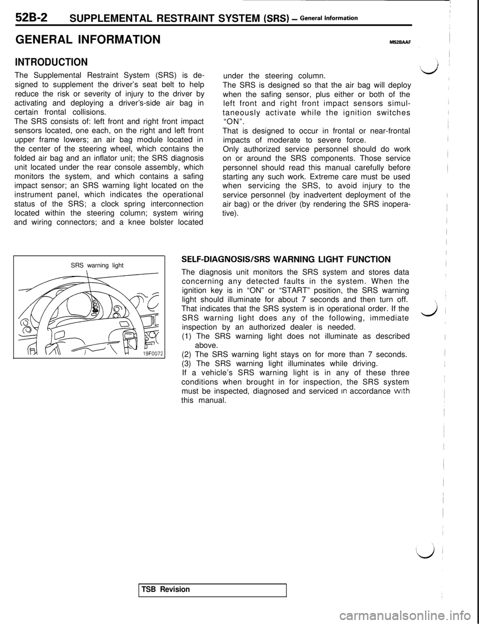
SRS warning light
M52BAAFunder the steering column.
The SRS is designed so that the air bag will deploy
when the safing sensor, plus either or both of the
left front and right front impact sensors simul-
taneously activate while the ignition switches
“ON”.
That is designed to occur in frontal or near-frontal
impacts of moderate to severe force.
Only authorized service personnel should do work
on or around the SRS components. Those service
personnel should read this manual carefully before
starting any such work. Extreme care must be used
whenservicing the SRS, to avoid injury to the
service personnel (by inadvertent deployment of the
air bag) or the driver (by rendering the SRS inopera-
tive).
SELF-DIAGNOSIS/SRS WARNING LIGHT FUNCTION
The diagnosis unit monitors the SRS system and stores data
concerning any detected faults in the system. When the
ignition key is in “ON” or “START” position, the SRS warning
light should illuminate for about 7 seconds and then turn off.
That indicates that the SRS system is in operational order. If the
SRS warning light does any of the following, immediate
inspection by an authorized dealer is needed.
(1) The SRS warning light does not illuminate as described
above.
(2) The SRS warning light stays on for more than 7 seconds.
(3) The SRS warning light illuminates while driving.
If a vehicle’s SRS warning light is in any of these three
conditions when brought in for inspection, the SRS system
must be inspected, diagnosed and serviced
In accordance wrth
this manual.
TSB Revision
Page 1015 of 1146

SUPPLEMENTAL RESTRAINT SYSTEM (SRS) - General lnform=*ion52B-5
r1.c
L
E.
,
iiCAUTION: SRS diagnosis unit
This unit cannot be repaired.
If defective, remove and replace entire unit per
service manual instructions.
Do not disassemble or tamper.
See service manual for handling and storage
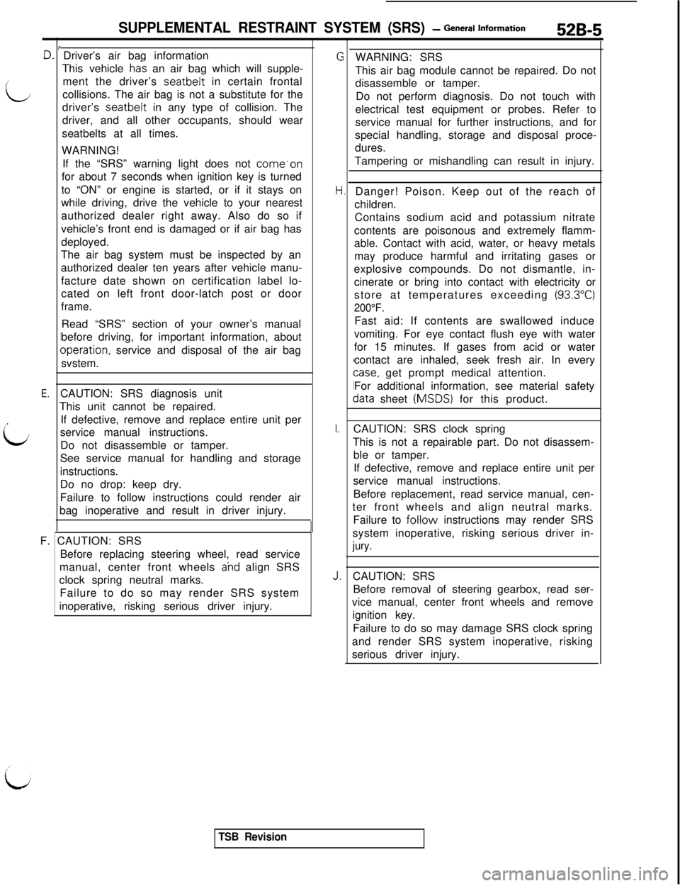
instructions.Driver’s air bag information
This vehicle
ha% an air bag which will supple-
ment the driver’s seatbelt in certain frontal
collisions. The air bag is not a substitute for the
driver’s seatbelt in any type of collision. The
driver, and all other occupants, should wear
seatbelts at all times.
WARNING!
If the “SRS” warning light does not come.on
for about 7 seconds when ignition key is turned
to “ON” or engine is started, or if it stays on
while driving, drive the vehicle to your nearest
authorized dealer right away. Also do so if
vehicle’s front end is damaged or if air bag has
deployed.
The air bag system must be inspected by an
authorized dealer ten years after vehicle manu-
facture date shown on certification label lo-
cated on left front door-latch post or door
frame.Read “SRS” section of your owner’s manual
before driving, for important information, about
Dperation, service and disposal of the air bag
svstem.
Do no drop: keep dry.
Failure to follow instructions could render air
bag inoperative and result in driver injury.
F. CAUTION: SRS
Before replacing steering wheel, read service
manual, center front wheels
ahd align SRS
clock spring neutral marks.
Failure to do so may render SRS system
inoperative, risking serious driver injury.
I.
J.WARNING: SRS
This air bag module cannot be repaired. Do not
disassemble or tamper.
Do not perform diagnosis. Do not touch with
electrical test equipment or probes. Refer to
service manual for further instructions, and for
special handling, storage and disposal proce-
dures.
Tampering or mishandling can result in injury.
Danger! Poison. Keep out of the reach of
children.
Contains sodium acid and potassium nitrate
contents are poisonous and extremely flamm-
able. Contact with acid, water, or heavy metals
may produce harmful and irritating gases or
explosive compounds. Do not dismantle, in-
cinerate or bring into contact with electricity or
store at temperatures exceeding
(93.3”C)
200°F.Fast aid: If contents are swallowed induce
vomiting. For eye contact flush eye with water
for 15 minutes. If gases from acid or water
contact are inhaled, seek fresh air. In every
case, get prompt medical attention.
For additional information, see material safety
data sheet (MSDS) for this product.
CAUTION: SRS clock spring
This is not a repairable part. Do not disassem-
ble or tamper.
If defective, remove and replace entire unit per
service manual instructions.
Before replacement, read service manual, cen-
ter front wheels and align neutral marks.
Failure to
foHow instructions may render SRS
system inoperative, risking serious driver in-
jury.CAUTION: SRS
Before removal of steering gearbox, read ser-
vice manual, center front wheels and remove
ignition key.
Failure to do so may damage SRS clock spring
and render SRS system inoperative, risking
serious driver injury.
TSB Revision