1991 MITSUBISHI 3000GT belt
[x] Cancel search: beltPage 1012 of 1146
52B-2SUPPLEMENTAL RESTRAINT SYSTEM (SRS) - General informationGENERAL INFORMATION
INTRODUCTIONThe Supplemental Restraint System (SRS) is de-
signed to supplement the driver’s seat belt to help
reduce the risk or severity of injury to the driver by
activating and deploying a driver’s-side air bag in
certain frontal collisions.
The SRS consists of: left front and right front impact
sensors located, one each, on the right and left front
upper frame lowers; an air bag module located in
the center of the steering wheel, which contains the
folded air bag and an inflator unit; the SRS diagnosis
unit located under the rear console assembly, which
monitors the system, and which contains a safing
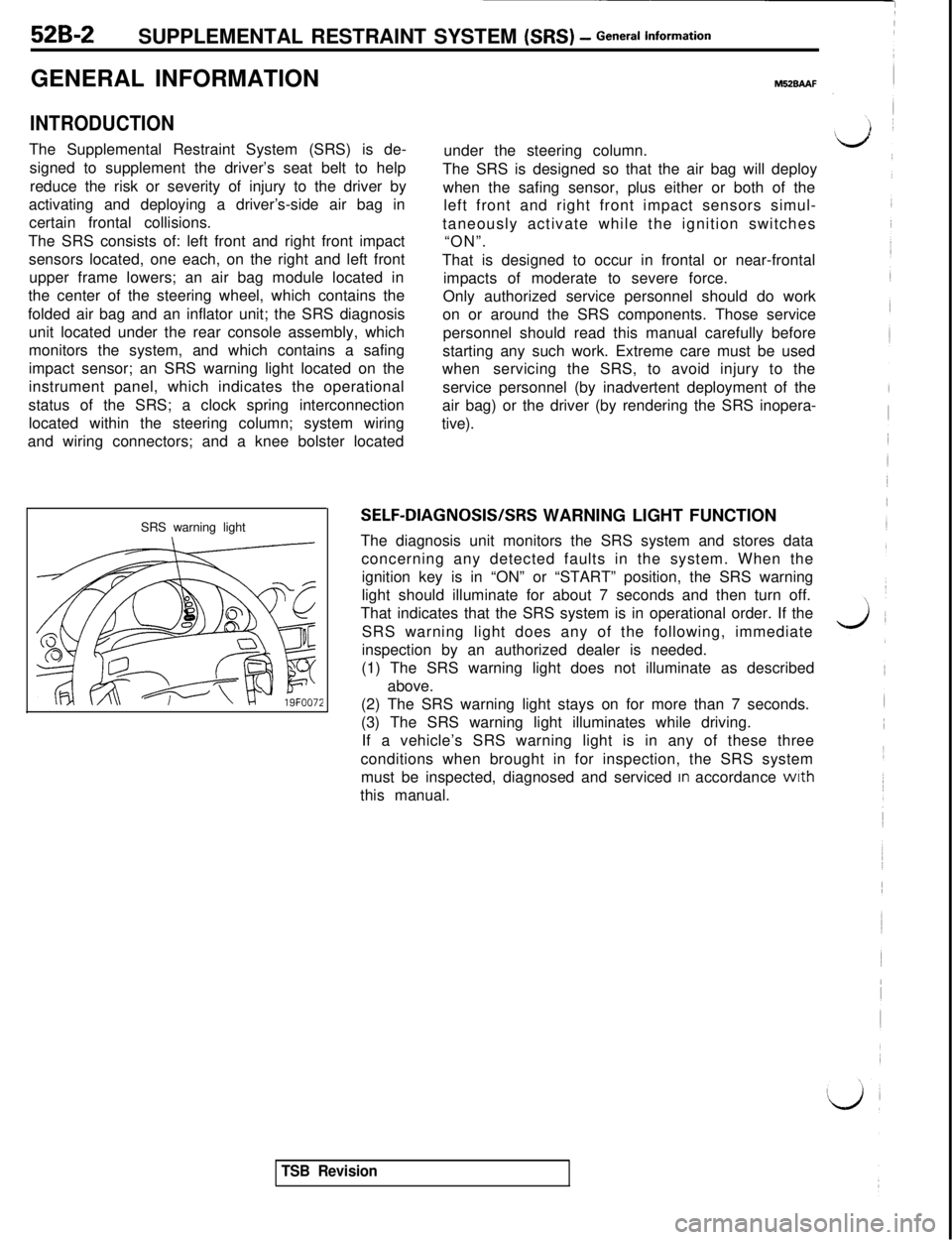
impact sensor; an SRS warning light located on the
instrument panel, which indicates the operational
status of the SRS; a clock spring interconnection
located within the steering column; system wiring
and wiring connectors; and a knee bolster located
SRS warning light
M52BAAFunder the steering column.
The SRS is designed so that the air bag will deploy
when the safing sensor, plus either or both of the
left front and right front impact sensors simul-
taneously activate while the ignition switches
“ON”.
That is designed to occur in frontal or near-frontal
impacts of moderate to severe force.
Only authorized service personnel should do work
on or around the SRS components. Those service
personnel should read this manual carefully before
starting any such work. Extreme care must be used
whenservicing the SRS, to avoid injury to the
service personnel (by inadvertent deployment of the
air bag) or the driver (by rendering the SRS inopera-
tive).
SELF-DIAGNOSIS/SRS WARNING LIGHT FUNCTION
The diagnosis unit monitors the SRS system and stores data
concerning any detected faults in the system. When the
ignition key is in “ON” or “START” position, the SRS warning
light should illuminate for about 7 seconds and then turn off.
That indicates that the SRS system is in operational order. If the
SRS warning light does any of the following, immediate
inspection by an authorized dealer is needed.
(1) The SRS warning light does not illuminate as described
above.
(2) The SRS warning light stays on for more than 7 seconds.
(3) The SRS warning light illuminates while driving.
If a vehicle’s SRS warning light is in any of these three
conditions when brought in for inspection, the SRS system
must be inspected, diagnosed and serviced
In accordance wrth
this manual.
TSB Revision
Page 1014 of 1146
52B-4SUPPLEMENTAL RESTRAINT SYSTEM (SRS) - General lnform=*ion
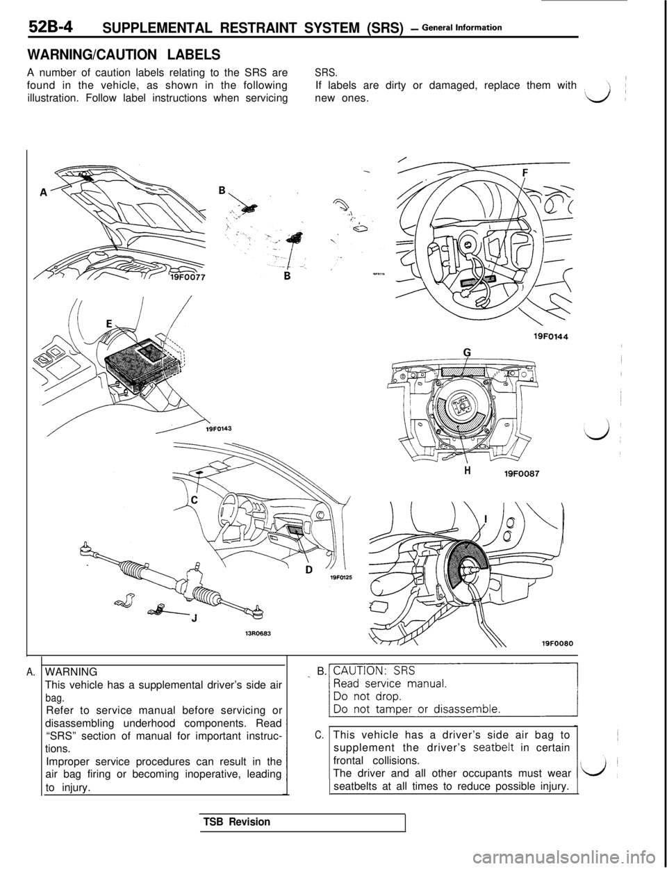
WARNING/CAUTION LABELSA number of caution labels relating to the SRS are
SRS.found in the vehicle, as shown in the followingIf labels are dirty or damaged, replace them with
illustration. Follow label instructions when servicingnew ones.
//----?9FO143
A.
H19FOO87
19FOO80WARNING
This vehicle has a supplemental driver’s side air
bag.Refer to service manual before servicing or
disassembling underhood components. Read
“SRS” section of manual for important instruc-
tions.
Improper service procedures can result in the
air bag firing or becoming inoperative, leading
to injury.
_ B. CAUTION: SRS
~1
C.This vehicle has a driver’s side air bag to
supplement the driver’s
seatbelt in certain
frontal collisions.
The driver and all other occupants must wear
seatbelts at all times to reduce possible injury.
TSB Revision
Page 1015 of 1146
SUPPLEMENTAL RESTRAINT SYSTEM (SRS) - General lnform=*ion52B-5
r1.c
L
E.
,
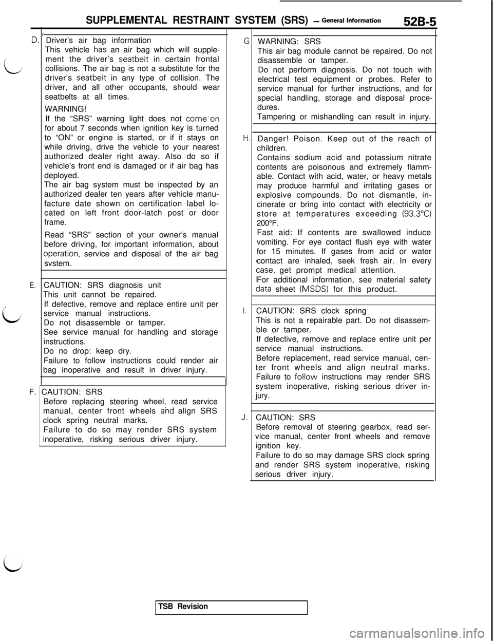
iiCAUTION: SRS diagnosis unit
This unit cannot be repaired.
If defective, remove and replace entire unit per
service manual instructions.
Do not disassemble or tamper.
See service manual for handling and storage
instructions.Driver’s air bag information
This vehicle
ha% an air bag which will supple-
ment the driver’s seatbelt in certain frontal
collisions. The air bag is not a substitute for the
driver’s seatbelt in any type of collision. The
driver, and all other occupants, should wear
seatbelts at all times.
WARNING!
If the “SRS” warning light does not come.on
for about 7 seconds when ignition key is turned
to “ON” or engine is started, or if it stays on
while driving, drive the vehicle to your nearest
authorized dealer right away. Also do so if
vehicle’s front end is damaged or if air bag has
deployed.
The air bag system must be inspected by an
authorized dealer ten years after vehicle manu-
facture date shown on certification label lo-
cated on left front door-latch post or door
frame.Read “SRS” section of your owner’s manual
before driving, for important information, about
Dperation, service and disposal of the air bag
svstem.
Do no drop: keep dry.
Failure to follow instructions could render air
bag inoperative and result in driver injury.
F. CAUTION: SRS
Before replacing steering wheel, read service
manual, center front wheels
ahd align SRS
clock spring neutral marks.
Failure to do so may render SRS system
inoperative, risking serious driver injury.
I.
J.WARNING: SRS
This air bag module cannot be repaired. Do not
disassemble or tamper.
Do not perform diagnosis. Do not touch with
electrical test equipment or probes. Refer to
service manual for further instructions, and for
special handling, storage and disposal proce-
dures.
Tampering or mishandling can result in injury.
Danger! Poison. Keep out of the reach of
children.
Contains sodium acid and potassium nitrate
contents are poisonous and extremely flamm-
able. Contact with acid, water, or heavy metals
may produce harmful and irritating gases or
explosive compounds. Do not dismantle, in-
cinerate or bring into contact with electricity or
store at temperatures exceeding
(93.3”C)
200°F.Fast aid: If contents are swallowed induce
vomiting. For eye contact flush eye with water
for 15 minutes. If gases from acid or water
contact are inhaled, seek fresh air. In every
case, get prompt medical attention.
For additional information, see material safety
data sheet (MSDS) for this product.
CAUTION: SRS clock spring
This is not a repairable part. Do not disassem-
ble or tamper.
If defective, remove and replace entire unit per
service manual instructions.
Before replacement, read service manual, cen-
ter front wheels and align neutral marks.
Failure to
foHow instructions may render SRS
system inoperative, risking serious driver in-
jury.CAUTION: SRS
Before removal of steering gearbox, read ser-
vice manual, center front wheels and remove
ignition key.
Failure to do so may damage SRS clock spring
and render SRS system inoperative, risking
serious driver injury.
TSB Revision
Page 1083 of 1146
55-1
HEATER, AIR
CONDITIONER
AND VENTILATION
CONTENTSM55AA- -
HEATERS AND AIR CONDITIONING................3HEATER UNIT*........................................................................22
SPECIFICATIONS
....................................................................3REFRIGERANT LINE................................................................35General Specifications
........................................................3RESISTOR................................................................................20Lubricants
............................................................................4SAFETY PRECAUTIONS........................................................9Sealant and Adhesive............................................................4
Service Specifications3SERVICE ADJUSTMENT PROCEDURES............................10........................................................
SPECIAL TOOLS4Charging Procedures............................................................11
i
........................................................................Charging the Refrigerant....................................................12Compressor Drive Belt Adjustment....................................11
HEATERS AND MANUAL AIR CONDITIONER5Compressor Noise................................................................16
................................................16
AIR CONDITIONER SWITCH................................................21Handling Tubing andFittings
Idle-up Operation Check....................................................17
BELT LOCK CONTROLLER20Performance Test................................................................15....................................................
BLOWER ASSEMBLYPower Relay Check............................................................17............................................................23Refrigerant Leak Repair Procedure....................................15COMPRESSOR........................................................................
27TestProcedures....................................................................10
CONDENSER AND CONDENSER FAN MOTOR................33TROUBLESHOOTING............................................................5
ENGINE COOLANT TEMPERATURE SWITCH....................
39VENTILATORS (AIR INLET AND AIR OUTLET)................38
EVAPORATOR
........................................................................
25VENTILATORS (INSTRUMENT PANEL)*............................36
HEATER CONTROL ASSEMBLY*
........................................18CONTINUED ON NEXT PAGE
SUPPLEMENTAL RESTRAINT SYSTEM (SRS)
(1)A Supplemental Restraint System (SRS), which uses a driver-side air bag, has been installed in the 3000GT.(2)The SRS includes the following components: impact sensors, SRS diagnosis unit: SRS warning light, air bagmodule, clock spring, interconnecting wiring. Other SRS-related components (that may have to be
removed/installed in connection with SRS service or maintenance) are indicated in the table of contents byan asterisk (*).
WARNING!(1)Improper service or maintenance of any component of the SRS, or any SRS-related component, can lead to
personal injury or death to service personnel (from inadvertent firing of the air bag) or to the driver (fromrendering the
SRS inoperative).(2) Service or maintenance of any SRS component or SRS-related component must be performed only at anauthorized MITSUBISHI dealer.
(3) MITSUBISHI dealer personnel must thoroughly review this manual, and especially its GROUP 52B
-Supplemental Restraint System (SRS), before beginning any service or maintenance of any component of theSRS or any SRS-related component.
Page 1084 of 1146

55-2FULL AUTO AIR CONDITIONER........................40OTHER PARTS........................................................................62
AIR-CONDITIONER CONTROL PANEL*,POWER TRANSISTOR, BELT LOCK CONTROLLER........57
AIR-CONDITIONER CONTROL UNIT*................................56
REFRIGERANT LINE................................................................62
COMPRESSOR
........................................................................62SAFETY PRECAUTlONS........................................................56
CONDENSER AND CONDENSER FAN MOTOR
................
62SENSORS....................................................................................60
DAMPER CONTROL MOTOR ASSEMBLY*........................
58SERVICE ADJUSTMENT PROCEDURES............................56
ENGINE COOLANT TEMPERATURE SWITCH
....................62
TROUBLESHOOTING............................................................40
Page 1085 of 1146
HEATER, AIR CONDITIONER AND VENTILATION - Specifications55-3
HEATER, AIR CONDITIONER AND VENTILATION
LSPECIFICATIONSM55CA. -
/’
L;
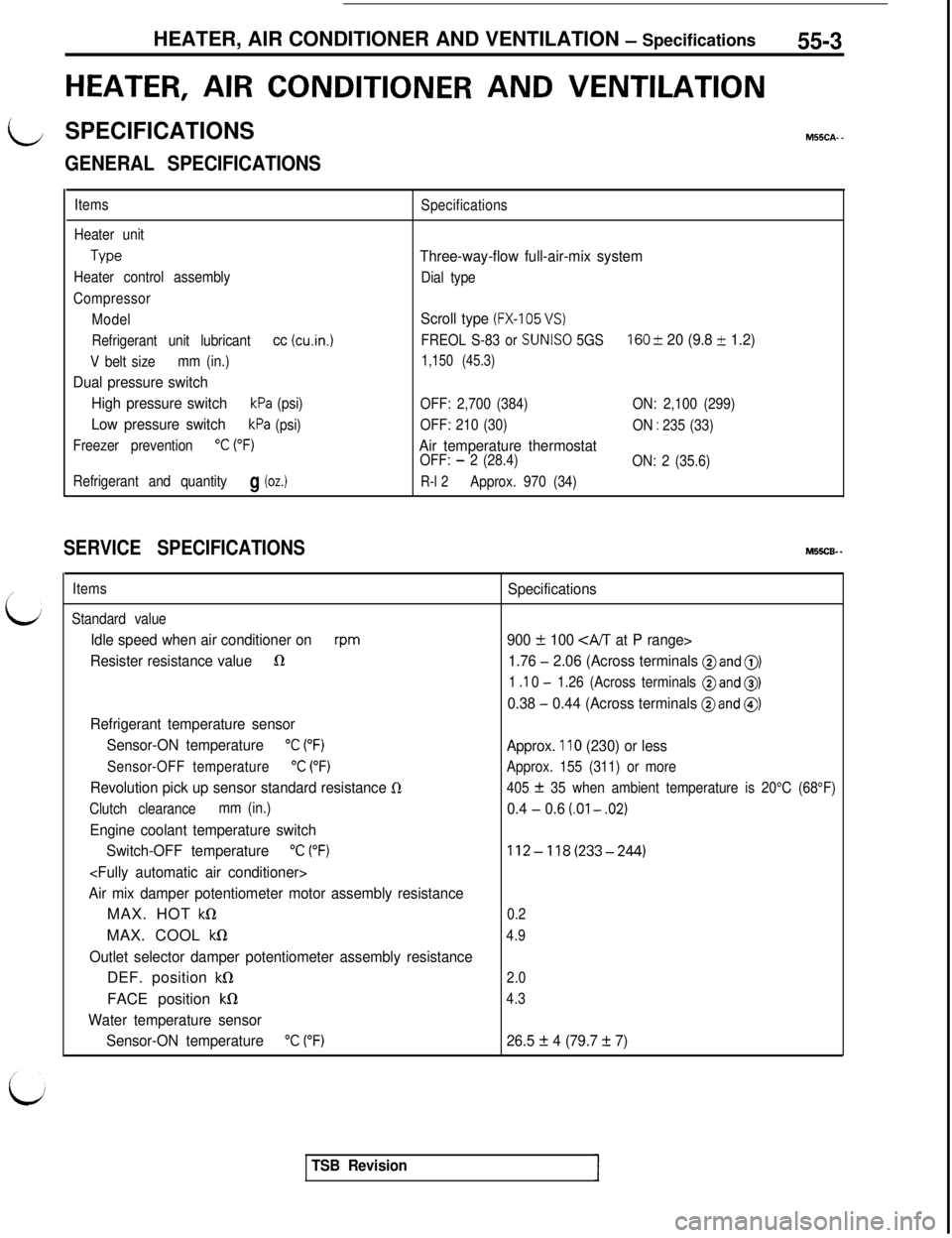
GENERAL SPECIFICATIONS
Items
Heater unit
Type
Heater control assembly
Compressor
Model
Refrigerant unit lubricant
cc (cu.in.1
V belt sizemm (in.)
Dual pressure switch
High pressure switch
kPa (psi)
Low pressure switchkPa (psi)
Freezer prevention
“C (“F)
Refrigerant and quantityg (oz.)
Specifications
Three-way-flow full-air-mix system
Dial type
Scroll type (FX-105 VS)
FREOL S-83 or SUNISO 5GS160 & 20 (9.8 + 1.2)
1,150 (45.3)
OFF: 2,700 (384)ON: 2,100 (299)
OFF: 210 (30)
ON
: 235 (33)
Air temperature thermostatOFF: - 2 (28.4)
ON: 2 (35.6)
R-l 2Approx. 970 (34)
SERVICE SPECIFICATIONSM55CB. -
Items
Standard value
Idle speed when air conditioner onrpm
Resister resistance value1R
Refrigerant temperature sensor
Sensor-ON temperature
“C (“F)
Sensor-OFF temperature“C (“F)
Revolution pick up sensor standard resistance 0
Clutch clearancemm (in.)
Engine coolant temperature switch
Switch-OFF temperature
“C (“F)
Air mix damper potentiometer motor assembly resistanceMAX. HOT
kQMAX. COOL
kS1
Outlet selector damper potentiometer assembly resistanceDEF. position
kS1FACE position
kfl
Water temperature sensor
Sensor-ON temperature
“C (“F)
Specifications
900
f 100 CA/T at P range>
1.76
- 2.06 (Across terminals @and 0)
1 .I 0 - 1.26 (Across terminals @and 0)
0.38 - 0.44 (Across terminals @and @)
Approx. 110 (230) or less
Approx. 155 (311) or more
405
f 35 when ambient temperature is 20°C (68°F)
0.4 - 0.6 (.Ol - .02)
112-118(233-244)
0.2
4.9
2.0
4.3
26.5 f 4 (79.7 + 7)
TSB Revision
Page 1093 of 1146
HEATERS AND MANUAL AIR CONDITIONER -Service Adjustment Procedures 55 1 1
lr In et sensor
UC03xD:c.-;am$2lYXSC0x.x
xa0:: :,:::25 cc,ii 77h>Temperature20A043F
argqse
20M012FIN-THERM0 SENSOR AND AIR-INLET SENSOR
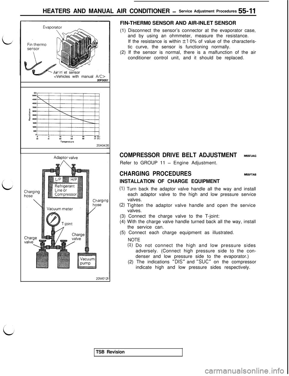
(1) Disconnect the sensor’s connector at the evaporator case,
and by using an ohmmeter, measure the resistance.
If the resistance is within
+I 0% of value of the characteris-
tic curve, the sensor is functioning normally.
(2) If the sensor is normal, there is a malfunction of the air
conditioner control unit, and it should be replaced.
COMPRESSOR DRIVE BELT ADJUSTMENTM55FJAGRefer to GROUP 11
- Engine Adjustment.
CHARGING PROCEDURESM55FTAB
INSTALLATION OF CHARGE EQUIPMENT
(I) Turn back the adaptor valve handle all the way and install
each adaptor valve to the high and low pressure service
valves.
(2) Tighten the adaptor valve handle and open the service
valves.
(3) Connect the charge valve to the T-joint:
(4) With the charge valve handle turned back all the way, install
the service can.
(5) Connect each charge equipment as illustrated.
NOTE
(4) Do not connect the high and low pressure sides
adversely. (Connect high pressure side to the con-
denser and low pressure side to the evaporator.)
(2) The indications
“DIS” and “SUC” on the compressor
indicate high and low pressure sides respectively.
TSB Revision
Page 1098 of 1146
55-16 HEATERS AND MANUAL AIR CONDITIONER -Service Adjustment Procedures
LOW CHARGE~
If the system has not lost all of its refrigerant charge; locate and
repair all leaks. If it is necessary to increase the system
pressure to find the leak (because of an especially low charge)
‘iaadd of refrigerant. If it is oossible to reoair the leak without
discharging-the refrigerant system, use the procedure for
correcting low refrigerant level.
HANDLING TUBING AND FITTINGSM55FlAFKinks in the refrigerant tubing or sharp bends in the refrigerant
hose lines will greatly reduce the capacity of the entire system.
High pressures are produced in the system when it is
operating. Extreme care must be exercised to make sure that
all connections are pressure tight. Dirt and moisture can enter
the system when it is opened for repair or replacement of lines
or components. The following precautions must be observed.
The system must be completely discharged before opening
any fitting of connection in the refrigeration system. Open
fittings with caution even after the system has been dis-
charged. If any pressure is noticed as a fitting is loosened, allow
trapped pressure to bleed off very slowly.
Never attempt to rebend formed lines to fit. Use the correct
line for the installation you are servicing.
A good rule for the flexible hose lines is keep the radius of all
bends at least 10 times the diameter of the hose.
Sharper bends will reduce the flow of refrigerant. The flexible
hose lines should be routed so that they are at least 80 mm (3
in.) from the exhaust manifold. It is good practice to inspect all
flexible hose lines at least once a year to make sure they are in
good condition and properly routed.
\ Aj iUnified plumbing connections with O-rings. These O-rings are
-not reusable.
I
COMPRESSOR NOISEM55FlAD
When investigating an air conditioning related noise, you must
first know the conditions when the noise occurs. These
conditions are: weather, vehicle speed, in gear on neutral,
engine temperature or any other special conditions.
Noises that develop during air conditioning operation can often
be misleading. For example: what sounds like a failed front
bearing or connecting rod. may be caused by loose bolts, nuts,
mounting brackets, or a loose clutch assembly. Verify acces-
sory drive belt tension (power steering or alternator).
Improper accessory drive belt tension can cause a misleading
noise when the compressor is engaged and little or no noise
when the compressor is disengaged.
Drive belts are speed sensitive. That is, at different engine
speeds, and depending upon belt tension, belts can develop
unusual noises that are often mistaken for mechanical prob-
lems within the compressor.
TSB Revision