1991 MITSUBISHI 3000GT charging
[x] Cancel search: chargingPage 311 of 1146

15-I
I
k..INTAKE AND ~
EXHAUST
=
CONTENTSME.AA- -
ACTIVE EXHAUST SYSTEM. . . . . . . . . . . . . . . . . . . . . . . . . . . .
AIR CLEANER. . . . . . . . . . . . . . . . . . . . . . . . . . . . . . . . . . . . . . . . . . . . . . . . . . . . . . . .
AIR INTAKE PLENUM
AIR INTAKE PLENUM
EXHAUST MANIFOLD
EXHAUST MANIFOLD
LEXHAUST PIPE, MAIN MUFFLER ANDCATALYTIC CONVERTER
CATALYTIC CONVERTER
INTAKE MANIFOLD. . . . . . . . . . . . . . . . . . . . . . . . . . . . . . . . . . . . . . . . . . . .
INTERCOOLER. . . . . . . . . . . . . . . . . . . . . . . . . . . . . . . . . . . . . . . . . . .
SERVICE ADJUSTMENT PROCEDURES. . . . . . . .Air Bypass Valve Inspection
. . . . . . . . . . . . . .._..Intake Manifold VacuumInspection
. . . . . . . . . . . . . . . .Supercharging Pressure Control System
Inspection
. . . . . . . . . . . . . . . . . . . . . . . . . . . . . . . . . . . . . . . . . . . . . . . . . . . . . . . . . . . .
33
9
13
14
27
28
30
31
16
11
6
8
8
7Supercharging Pressure Relief Solenoid
ValveInspection
. . . . . . . . . . . . . . . . . . . . . . . . . . . . . . . . . . . . . .._........Turbocharger Supercharging Pressure
Inspection
. . . . . . . . . . .._................................._.___.........Variable Induction Control System
Inspection
. . . . . . . . . . . . . . . . . . . . . . . . . . . . . . . . . . . . . . . . . . . . . . . . . . . . .._.....
SPECIAL TOOL. . . . . . . . . . . . . . . . . . . . . . . . . . . . . . . . . . . . . . . . . . . .._____..
SPECIFICATIONS................................................General Specifications
....................................Service Specifications
....................................
TROUBLESHOOTING. . . . . . . . . . . . . . . . . . . . . . . . . . . . .._._.._....Abnormal Noise
Exhaust Gas Leakage
TROUBLESHOOTING
(Active Exhaust System)
. . . . . . . . . . . . . . . . . . . . . . ..________....
TURBOCHARGER. . . . . . . . . . . . . . . . . . . . . . . . . . . . . . . . . . . . . . . . . . . . . . . .
TURBOCHARGER(FRONT). . . . . . . . . . . . . . . . . . . . . . . . . . . . . . . .
TURBOCHARGER (REAR). . . . . . . . . . . . . . . .8
6
4
24
18
21
Page 312 of 1146

15-2INTAKE AND EXHAUST - Specifications / Special Tool
SPECIFICATIONS
GENERAL SPECIFICATIONS
Items
Air cleaner
Element
Exhaust system
Front exhaust pipe
Muffler
Coupling
Suspension system
Turbocharger
We
identification No.
Supercharging pressure control
Intercooler
Type
SERVICE SPECIFICATIONSMlSCA-
Specifications
Unwoven cloth type
Dual type
Expansion resonance type
Flat coupling, insertion type
Rubber hangers
Exhaust gas turbine type
TD04-09BS-6
Waste gate actuator and solenoid valve
Air cooled type
MVXB-.
Items
Intake and exhaust manifolds
Distortion oJcnylirrdjer head contactingsurface
Supercharging pressure solenoid valve
terminal resistance [at 20°C (68”F)lQ
Turbocharger
Supercharging pressure
kPa (psi)
Waste gate valve opening pressure
kPa (psi)
Standard
Less than 0.15 (.0059)36-44
Approx. 20 - 60 (2.9 - 8.7)
Approx. 48 (6.8)
Limit
0.2
f.008)
SPECIAL TOOLMlSDA- -
ToolNumber
MD998770
Name
Oxygen sensor
wrench
Use
Removal/Installation of oxygen sensor
J
iJ
TSB Revision
Page 316 of 1146

15-6INTAKE AND EXHAUST - Service Adjustment Procedures
Variable rnductiorcontrol servoconnectors
6FU1277
Open
Close
71 NO105
SERVICE ADJUSTMENT PROCEDURESMlSGlAA
VARIABLE INDUCTION CONTROL SYSTEM IN-
d
SPECTION (Non Turbo)
SYSTEM INSPECTION
(1) Warm up the engine.
(2) Connect the tachometer. (Refer to GROUP 11 - Engine
Adjustment.)
(3) Make sure that when the engine speed is increased from
the idle speed to 5,000 rpm, the induction control valve
shaft turns.
VARIABLE INDUCTION CONTROL SERVO INSPECTION
(1) Disconnect the variable induction control servo connectors.
(2)
Teck the vanable induction control servo coil for continui-
Standard value
Measured terminalBetween terminals
@ and @]Continuity
Present
15 - 35 0: 20°C (68”F)I
(3) Make sure that when DC 6V is applied to terminals @ and@ of the variable induction control servo connector, the
induction control valve shaft turns smoothly.
Caution
Be sure to apply a voltage of not higher than DC 6V tothe variable induction control servo connector termi-4nals since application of high voltage may lock the
servo gears.
(4) If deviation from the standard value.occurs or the variable
induction control valve shaft does not turn smoothly,
replace the air intake plenum assembly.
TURBOCHARGER SUPERCHARGING PRESSURE
INSPECTION (Turbo)MlSGAAC
CautionPerform running inspection with two passengers in the
vehicle and where full throttle acceleration can be safely
made.The pressure gauge reading is taken by a front seat
passenger.‘,k,i
TSB Revision
Page 317 of 1146

INTAKE AND EXHAUST - Service Adiustment Procedures15-7
(1) Disconnect the hose (black) from the waste gate solenoid
valve, and connect the pressure gauge to the hose. Plug the
nipple of the solenoid valve from which the hose (black) has
been disconnected.
(2) Drive the vehicle with full throttle and accelerate the engine
to a speed of more than 3,500 rpm at 2nd gear. Measure
the supercharging pressure when the pointer is stabilized.
Standard value: 20
- 60 kPa (2.9 - 8.7 psi)
Caution
If the supercharging pressure deviates from the stan-dard value, check the following items for possible
causes.When pressure is high:
Waste gate actuator malfunction
When pressure is low:
Waste gate actuator malfunction
Supercharging pressure leaks
Faulty turbocharger
SUPERCHARGING PRESSURE CONTROL SYS-
TEM INSPECTION (Turbo)MlSGFAB
(1) After the self-diagnosis code of MPI system is completely
read, turn off the ignition switch.
(2) Disconnect the hose (black) from the waste gate solenoid
valve and connect a three-way joint between the hose and
the solenoid.
(3) Conncet a hand vacuum pump to the three-way joint.
(4) Disconnect the hose (with its end painted red) from the
wastegate actuator control boost nipple and plug the nipple.
(5) Disconnect the battery negative cable from the battery
terminal for 10 seconds or more and connect it again.
(6) Applying a negative pressure with the hand vacuum pump,
check tightness both when the hose end (with its end
painted red) is closed and when it is open.
EngineHoseNormal state
state(with its end painted red)
stop
OpenedNegative pressure leaks.
(Ignition
switch:Closed by fingerNegative pressure is
ON)maintained.
IdlingClosed by finger
Negative pressure leaks.
NOTEIf this check indicates an abnormal condition, the waste
gate actuator, waste gate solenoid valve or hose is broken.
1 TSB Revision
Page 318 of 1146

INTAKE AND EXHAUST - Service Adiustment Procedures
SUPERCHARGING PRESSURE RELIEF SOLENOID
VALVE INSPECTION (Turbo)
OPERATION INSPECTION
(1) Connect a hand vacuum pump to the solenoid valve nipple@ (see the illustration to the left).
(2) Using a jumper wire, connect between the solenoid valve
terminal and battery terminal.
(3) Connecting and disconnecting the jumper wire at the
battery negative terminal to apply a negative pressure,
check tightness.
Jumper wire
@I nippleNormal conditioncondition
Connected
Disconnected
OpenNegative pressure leaks.
CloseNegative pressure is held.
OpenNegative pressure is held.
COIL RESISTANCE INSPECTIONMeasure resistance between solenoid valve terminals
Standard value: 36
- 44 0 [at 20°C (68”F)I
AIR BYPASS VALVE INSPECTION (Turbo)MlSGHAB
(1) Remove the air bypass valve.
(2) Connect the hand vacuum pump to the nipple of the air
bypass valve.
(3) Apply a negative pressure of approx. 400 mmHg (16
in.Hg),and check operation of the valve. Also check that air
tightness is maintained.
Negative pressure
About 400
mmHg (16 in.Hg)
Valve operation
It starts opening
INTAKE MANIFOLD VACUUM INSPECTIONM’ISGCACRefer to GROUP 11
‘- Service Adjustment Procedures.
TSB Revision
Page 1083 of 1146

55-1
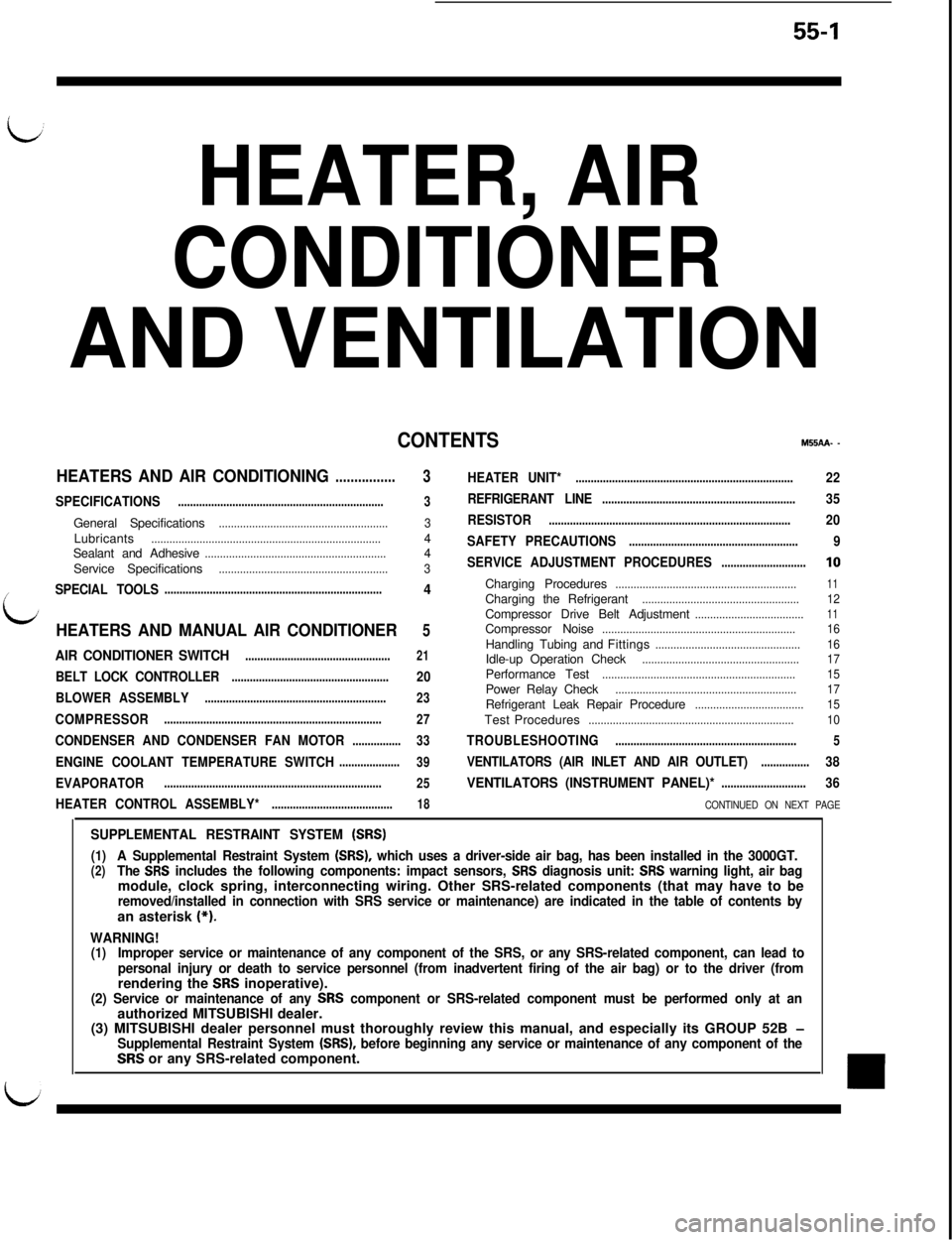
HEATER, AIR
CONDITIONER
AND VENTILATION
CONTENTSM55AA- -
HEATERS AND AIR CONDITIONING................3HEATER UNIT*........................................................................22
SPECIFICATIONS
....................................................................3REFRIGERANT LINE................................................................35General Specifications
........................................................3RESISTOR................................................................................20Lubricants
............................................................................4SAFETY PRECAUTIONS........................................................9Sealant and Adhesive............................................................4
Service Specifications3SERVICE ADJUSTMENT PROCEDURES............................10........................................................
SPECIAL TOOLS4Charging Procedures............................................................11
i
........................................................................Charging the Refrigerant....................................................12Compressor Drive Belt Adjustment....................................11
HEATERS AND MANUAL AIR CONDITIONER5Compressor Noise................................................................16
................................................16
AIR CONDITIONER SWITCH................................................21Handling Tubing andFittings
Idle-up Operation Check....................................................17
BELT LOCK CONTROLLER20Performance Test................................................................15....................................................
BLOWER ASSEMBLYPower Relay Check............................................................17............................................................23Refrigerant Leak Repair Procedure....................................15COMPRESSOR........................................................................
27TestProcedures....................................................................10
CONDENSER AND CONDENSER FAN MOTOR................33TROUBLESHOOTING............................................................5
ENGINE COOLANT TEMPERATURE SWITCH....................
39VENTILATORS (AIR INLET AND AIR OUTLET)................38
EVAPORATOR
........................................................................
25VENTILATORS (INSTRUMENT PANEL)*............................36
HEATER CONTROL ASSEMBLY*
........................................18CONTINUED ON NEXT PAGE
SUPPLEMENTAL RESTRAINT SYSTEM (SRS)
(1)A Supplemental Restraint System (SRS), which uses a driver-side air bag, has been installed in the 3000GT.(2)The SRS includes the following components: impact sensors, SRS diagnosis unit: SRS warning light, air bagmodule, clock spring, interconnecting wiring. Other SRS-related components (that may have to be
removed/installed in connection with SRS service or maintenance) are indicated in the table of contents byan asterisk (*).
WARNING!(1)Improper service or maintenance of any component of the SRS, or any SRS-related component, can lead to
personal injury or death to service personnel (from inadvertent firing of the air bag) or to the driver (fromrendering the
SRS inoperative).(2) Service or maintenance of any SRS component or SRS-related component must be performed only at anauthorized MITSUBISHI dealer.
(3) MITSUBISHI dealer personnel must thoroughly review this manual, and especially its GROUP 52B
-Supplemental Restraint System (SRS), before beginning any service or maintenance of any component of theSRS or any SRS-related component.
Page 1091 of 1146

HEATERS AND MANUAL AIR CONDITIONER - safety Pre=utm55-9
SAFETY PRECAUTIONSR-12 refrigerant is a chlorofluoro-carbon
(CFC) that
can contribute to the depletion of the ozone layer in
the upper atmosphere.
Ozone filters out harmful radiation from the sun.
To assist in protecting the ozone layer, Mitsubishi
Motor Sales of America recommends that a R-12
refrigerant recycling device that meets SAE stan-
dard
J1991 be used.
Contact an automotive service equipment supplier
for refrigerant recycling equipment that is available
in your area.
The refrigerant used in all air conditioner is R-l 2. It is
transparent and colorless in both the liquid and
vapor state. Since it has a boiling point of
-29.8”C(-21.7”F), at atmospheric pressure, it will be a vapor
at all normal temperatures and pressures. The vapor
is heavier than air, non-flammable, and nonexplo-
sive. It is nonpoisonous except when it is in direct
contact with open flame. It is noncorrosive except
when combined with water. The following precau-
tions must be observed when handling R-12.
CautionWear safety goggles when servicing the refri-
geration system.R-12 evaporates so rapidly at normal atmospheric
pressures and temperatures that it tends to freeze
anything it contacts. For this reason, extreme care
must be taken to prevent any liquid refrigerant from
contacting the skin and especially the eyes. Always
wear safety goggles when servicing the refrigera-
tion part of the air conditioning system. Keep a
bottle of sterile mineral oil handy when working on
the refrigeration system. Should any liquid re-
frigerant get into the eyes, use a few drops of
mineral oil to wash them out. R-12 is rapidly
absorbed by the oil. Next splash the eyes with
plenty of cold water. Call your doctor immediately
even though irritation has ceased after treatment.
CautionDo not heat R-12 above 52°C
(125.6”F).
M55PAAFIn most instances, moderate heat is required to
bring the pressure of the refrigerant in its container
above the pressure of the system when charging or
adding refrigerant. A bucket or large pan of hot
water not over 52°C
(125.6”F) is all the heat required
for this purpose. Do not heat the refrigerant contain-
er with a blow torch or any other means that would
raise temperature and pressure above this tempera-
ture. Do not weld or steam clean on or near the
system components or refrigerant lines.
Caution
Keep R-12 containers upright when charging the
system.When metering R-12 into the refrigeration system,
keep the supply tank or cans in an upright position. If
the refrigerant container is on its side or upside
down, liquid refrigerant will enter the system and
damage the compressor.
CautionAlways work in a well-ventilated room.
Good ventilation is vital in the working area.
Although R-12 vapor is normally nonpoisonous,
contact with an open flame can cause the vapor to
become very poisonous. A poisonous gas is pro-
duced when using the flame-type leak detector.
Avoid inhaling the fumes from the leak detector.
CautionDo not allow liquid refrigerant to touch bright
metal.Refrigerant will tarnish bright metal and chrome
surfaces, and in combination with moisture can
severely corrode all metal surfaces.
1 TSB Revision
Page 1092 of 1146

55-10 HEATERS AND MANUAL AIR CONDITIONER -Service Adjustment Procedures
OFF-----__-__1210235 2,1002,700
(30) (33)(299) (384)
Pressure Fil
2OPOOlL
SERVICE ADJUSTMENT PROCEDURES
M55FEAU
TEST PROCEDURESSIGHT GLASS REFRIGERANT LEVEL TEST
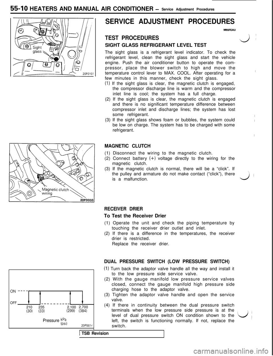
The sight glass is a refrigerant level indicator. To check the
refrigerant level, clean the sight glass and start the vehicle
engine. Push the air conditioner button to operate the com-
pressor, place the blower switch to high and move the
temperature control lever to MAX. COOL. After operating for a
few minutes in this manner, check the sight glass.
(I) If the sight glass is clear, the magnetic clutch is engaged,
the compressor discharge line is warm and the compressor
inlet line is cool; the system has a full charge.
(2) If the sight glass is clear, the magnetic clutch is engaged
and there is no significant temperature difference between
compressor inlet and discharge lines; the system has lost
some refrigerant.
(3) If the sight glass shows foam or bubbles, the system could
be low on charge. The system has to be charged with some
refrigerant.
MAGNETIC CLUTCH(1) Disconnect the wiring to the magnetic clutch.
(2) Connect battery (+) voltage directly to the wiring for the
magnetic clutch.
(3) If the magnetic clutch is normal, there will be a “click”. If
the pulley and armature do not make contact (“click”), there
is a malfunction.
v):
I
I
I
I
\,
3’
RECEIVER DRIERTo Test the Receiver Drier
(1) Operate the unit and check the piping temperature by
touching the receiver drier outlet and inlet.
(2) If there is a difference in the temperatures, the receiver
drier is restricted.
Replace the receiver drier.
DUAL PRESSURE SWITCH (LOW PRESSURE SWITCH)
(I) Turn back the adaptor valve handle all the way and install it
to the low pressure side service valve.
(2) With the gauge manifold low pressure service valves
closed, connect the gauge manifold high pressure side
charging hose to the adaptor valve.
(3) Tighten the adaptor valve handle and open the service
valve.
(4) If there in continuity between the dual pressure switch
terminals when the low pressure side pressure is at the
level of dual pressure switch ON condition shown to the
left, the switch is functioning normally. If not, replace the
L/(switch.
1 TSB Revision