1991 MITSUBISHI 3000GT charging
[x] Cancel search: chargingPage 1093 of 1146
HEATERS AND MANUAL AIR CONDITIONER -Service Adjustment Procedures 55 1 1
lr In et sensor
UC03xD:c.-;am$2lYXSC0x.x
xa0:: :,:::25 cc,ii 77h>Temperature20A043F
argqse
20M012FIN-THERM0 SENSOR AND AIR-INLET SENSOR
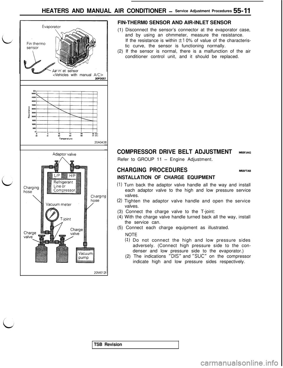
(1) Disconnect the sensor’s connector at the evaporator case,
and by using an ohmmeter, measure the resistance.
If the resistance is within
+I 0% of value of the characteris-
tic curve, the sensor is functioning normally.
(2) If the sensor is normal, there is a malfunction of the air
conditioner control unit, and it should be replaced.
COMPRESSOR DRIVE BELT ADJUSTMENTM55FJAGRefer to GROUP 11
- Engine Adjustment.
CHARGING PROCEDURESM55FTAB
INSTALLATION OF CHARGE EQUIPMENT
(I) Turn back the adaptor valve handle all the way and install
each adaptor valve to the high and low pressure service
valves.
(2) Tighten the adaptor valve handle and open the service
valves.
(3) Connect the charge valve to the T-joint:
(4) With the charge valve handle turned back all the way, install
the service can.
(5) Connect each charge equipment as illustrated.
NOTE
(4) Do not connect the high and low pressure sides
adversely. (Connect high pressure side to the con-
denser and low pressure side to the evaporator.)
(2) The indications
“DIS” and “SUC” on the compressor
indicate high and low pressure sides respectively.
TSB Revision
Page 1094 of 1146
55-12 HEATERS AND MANUAL AIR CONDITIONER - Service Adjustment Procedures
CHARGING SYSTEMAdaDtor valve
Vacuum meter20MOli
l-TSB IHold this conditron
for 5 minutes.
Gas leak check
is evident
1
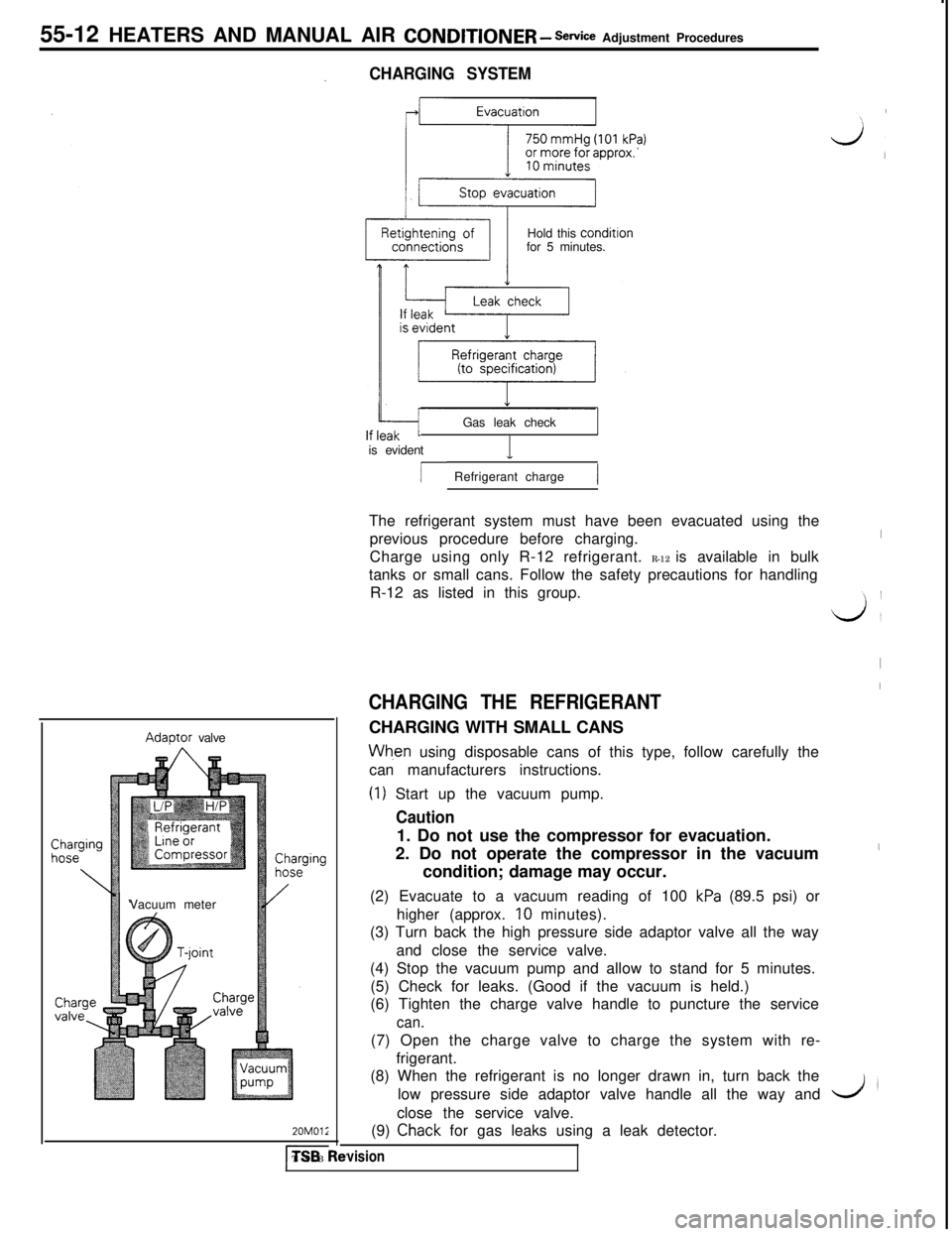
/ Refrigerant charge1The refrigerant system must have been evacuated using the
previous procedure before charging.
Charge using only R-12 refrigerant. R-12 is available in bulk
tanks or small cans. Follow the safety precautions for handling
R-12 as listed in this group.
CHARGING THE REFRIGERANTCHARGING WITH SMALL CANS
Wh,en using disposable cans of this type, follow carefully the
can manufacturers instructions.
(1) Start up the vacuum pump.
Caution1. Do not use the compressor for evacuation.
2. Do not operate the compressor in the vacuum
condition; damage may occur.
(2) Evacuate to a vacuum reading of 100
kPa (89.5 psi) or
higher (approx. IO minutes).
(3) Turn back the high pressure side adaptor valve all the way
and close the service valve.
(4) Stop the vacuum pump and allow to stand for 5 minutes.
(5) Check for leaks. (Good if the vacuum is held.)
(6) Tighten the charge valve handle to puncture the service
can.(7) Open the charge valve to charge the system with re-
frigerant.
(8) When the refrigerant is no longer drawn in, turn back the
low pressure side adaptor valve handle all the way and
close the service valve.
(9)
Chack for gas leaks using a leak detector.
vision
I
J’
I
I
I
L./l
Page 1095 of 1146
HEATERS AND MANUAL AIR CONDITIONER - Service AdWment proceres 55-13. .
Charginglose
\Adaptor valve
Vacuum meter
T-joint
20M0121
(1O)Start the engine.(1l)Operate the air conditioner and set at the lowest tempera-
ture (MAX. COOL).
(12)Fix the engine speed at 1,500 rpm.
(13)Tighten the low pressure side adaptor valve and open the
service valve to charge specified amount of refrigerant.
Caution
If the service can is inverted, liquid refrigerant may bedrawn into the compressor damaging it by liquid
compression. Keep the service can upright to ensurethat refrigerant is charged in gas state.
(14)Upon completion of charging, turn back the low pressure
side adaptor valve handle all the way and close the service
valve.
CHARGING WITH REFRIGERANT RECOVERY AND RE-
CYCLING UNITWhen using refrigerant recovery and recycling unit, follow
carefully the instruction manual for the unit.
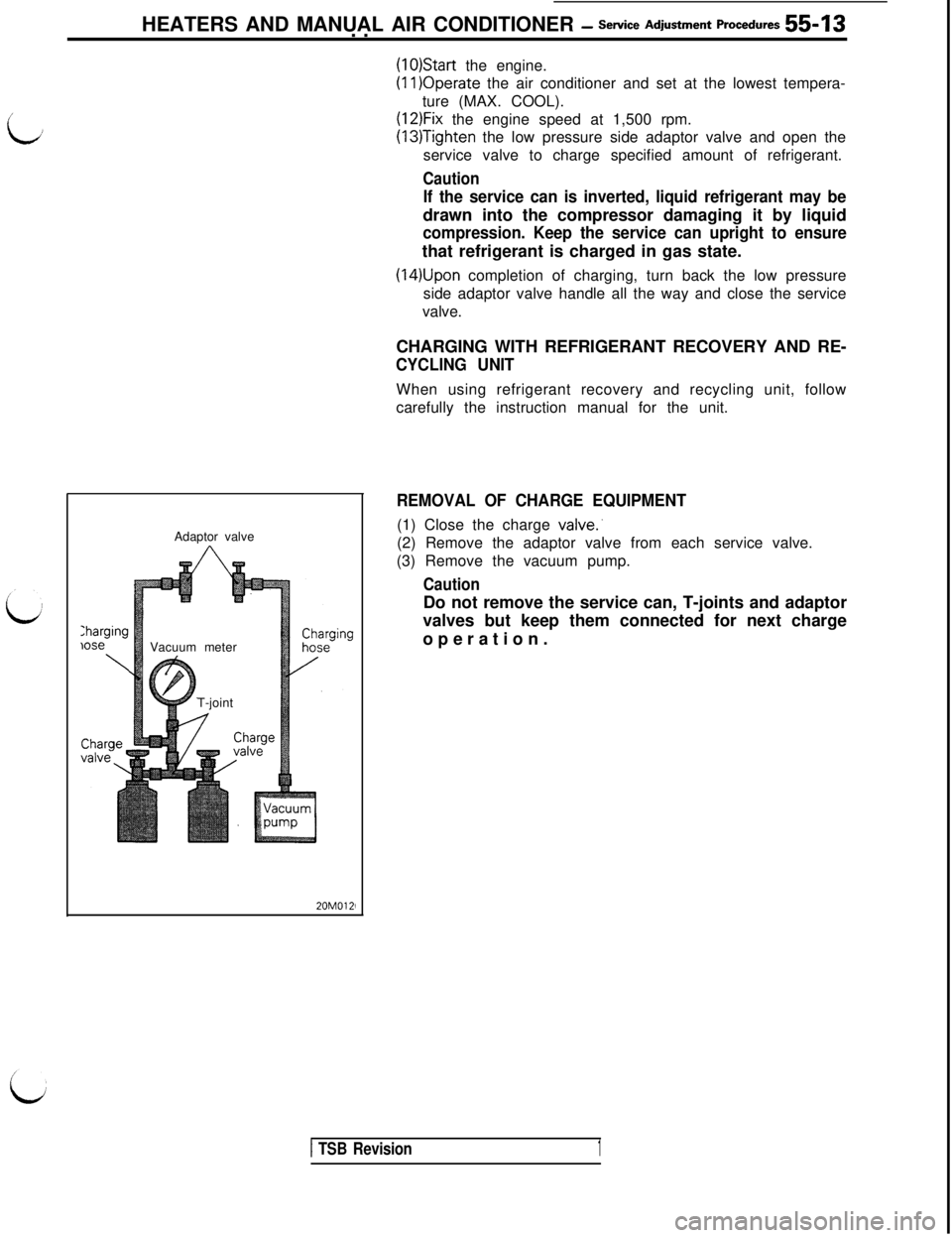
REMOVAL OF CHARGE EQUIPMENT(1) Close the charge
valve:(2) Remove the adaptor valve from each service valve.
(3) Remove the vacuum pump.
CautionDo not remove the service can, T-joints and adaptor
valves but keep them connected for next charge
operation.
1 TSB Revision1
Page 1096 of 1146
CautionRefrigerantR-l 2iAdaptorNever use the high pressure side as this may cause
/valve
refrigerant to flow back, using rupture of the servicecan.(7) Start the engine. Charge valvergmg hose
55-14 HEATERS AND MANUAL AIR CONDITIONER - Service Adjustment procedures
CORRECTING LOW REFRIGERANT LEVEL
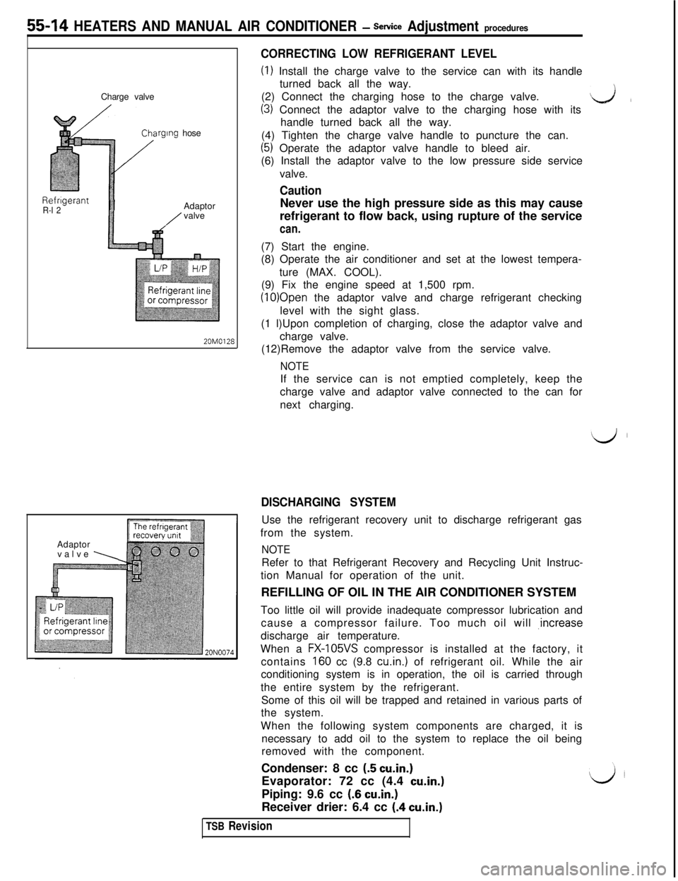
(I) Install the charge valve to the service can with its handle
turned back all the way.
(2) Connect the charging hose to the charge valve.
(3) Connect the adaptor valve to the charging hose with itsL&lhandle turned back all the way.
(4) Tighten the charge valve handle to puncture the can.
(5) Operate the adaptor valve handle to bleed air.
(6) Install the adaptor valve to the low pressure side service
valve.
(8) Operate the air conditioner and set at the lowest tempera-
ture (MAX. COOL).
(9) Fix the engine speed at 1,500 rpm.
(10)Open the adaptor valve and charge refrigerant checking
level with the sight glass.
(1 l)Upon completion of charging, close the adaptor valve and
20M0128charge valve.
(12)Remove the adaptor valve from the service valve.
NOTEIf the service can is not emptied completely, keep the
charge valve and adaptor valve connected to the can for
next charging.
Adaptor
valve
\
DISCHARGING SYSTEMUse the refrigerant recovery unit to discharge refrigerant gas
from the system.
NOTERefer to that Refrigerant Recovery and Recycling Unit Instruc-
tion Manual for operation of the unit.
REFILLING OF OIL IN THE AIR CONDITIONER SYSTEM
Too little oil will provide inadequate compressor lubrication and
cause a compressor failure. Too much oil will ,increase
discharge air temperature.
When a
FX-105VS compressor is installed at the factory, it
contains
160 cc (9.8 cu.in.) of refrigerant oil. While the air
conditioning system is in operation, the oil is carried through
the entire system by the refrigerant.
Some of this oil will be trapped and retained in various parts of
the system.
When the following system components are charged, it is
necessary to add oil to the system to replace the oil being
removed with the component.
Condenser: 8 cc
(5 cu.in.)Evaporator: 72 cc (4.4
cu.in.)Piping: 9.6 cc
(6 cu.in.)Receiver drier: 6.4 cc
(.4 cu.in.)
TSB Revision
Page 1098 of 1146
55-16 HEATERS AND MANUAL AIR CONDITIONER -Service Adjustment Procedures
LOW CHARGE~
If the system has not lost all of its refrigerant charge; locate and
repair all leaks. If it is necessary to increase the system
pressure to find the leak (because of an especially low charge)
‘iaadd of refrigerant. If it is oossible to reoair the leak without
discharging-the refrigerant system, use the procedure for
correcting low refrigerant level.
HANDLING TUBING AND FITTINGSM55FlAFKinks in the refrigerant tubing or sharp bends in the refrigerant
hose lines will greatly reduce the capacity of the entire system.
High pressures are produced in the system when it is
operating. Extreme care must be exercised to make sure that
all connections are pressure tight. Dirt and moisture can enter
the system when it is opened for repair or replacement of lines
or components. The following precautions must be observed.
The system must be completely discharged before opening
any fitting of connection in the refrigeration system. Open
fittings with caution even after the system has been dis-
charged. If any pressure is noticed as a fitting is loosened, allow
trapped pressure to bleed off very slowly.
Never attempt to rebend formed lines to fit. Use the correct
line for the installation you are servicing.
A good rule for the flexible hose lines is keep the radius of all
bends at least 10 times the diameter of the hose.
Sharper bends will reduce the flow of refrigerant. The flexible
hose lines should be routed so that they are at least 80 mm (3
in.) from the exhaust manifold. It is good practice to inspect all
flexible hose lines at least once a year to make sure they are in
good condition and properly routed.
\ Aj iUnified plumbing connections with O-rings. These O-rings are
-not reusable.
I
COMPRESSOR NOISEM55FlAD
When investigating an air conditioning related noise, you must
first know the conditions when the noise occurs. These
conditions are: weather, vehicle speed, in gear on neutral,
engine temperature or any other special conditions.
Noises that develop during air conditioning operation can often
be misleading. For example: what sounds like a failed front
bearing or connecting rod. may be caused by loose bolts, nuts,
mounting brackets, or a loose clutch assembly. Verify acces-
sory drive belt tension (power steering or alternator).
Improper accessory drive belt tension can cause a misleading
noise when the compressor is engaged and little or no noise
when the compressor is disengaged.
Drive belts are speed sensitive. That is, at different engine
speeds, and depending upon belt tension, belts can develop
unusual noises that are often mistaken for mechanical prob-
lems within the compressor.
TSB Revision
Page 1099 of 1146
HEATERS AND MANUAL AIR CbNDlTlONER -Service Adjustment Procedures 55 17
ADJUSTMENT PROCEDURES(1) Select a quiet area for testing. Duplicate conditions as much
as possible. Switch compressor on and off several times to
clearly identify compressor noise.
To duplicate high ambient conditions (high head pressure),
restrict air flow through condenser. Install manifold gauge
set to make sure discharge pressure doesn’t exceed 2,070
kPa (300 psi).
(2) Tighten all compressor mounting bolts, clutch mounting
bolt, and compressor drive belt. Check to assure clutch coil
is tight (no rotation or wobble).
(3) Check refrigerant hoses for rubbing or interference that can
cause unusual noises.
(4) Check refrigerant charge. (See “Charging System”.)
(5) Recheck compressor noise as in Step 1.
(6) If noise still exists, loosen compressor mounting bolts and
retorque. Repeat Step 1.
(7) If noise continues, replace compressor and repeat Step 1.
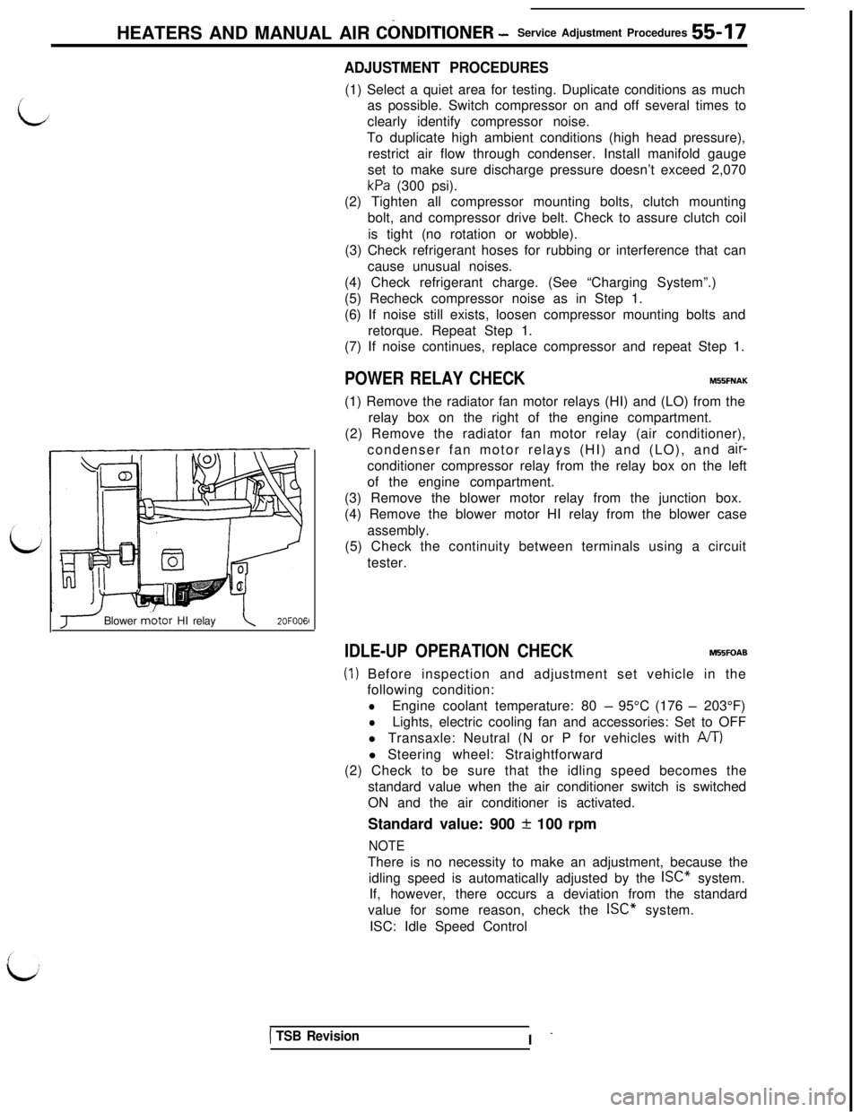
POWER RELAY CHECKMBBFNAK(1) Remove the radiator fan motor relays (HI) and (LO) from the
relay box on the right of the engine compartment.
(2) Remove the radiator fan motor relay (air conditioner),
condenser fan motor relays (HI) and (LO), and
air-conditioner compressor relay from the relay box on the left
of the engine compartment.
(3) Remove the blower motor relay from the junction box.
(4) Remove the blower motor HI relay from the blower case
assembly.
(5) Check the continuity between terminals using a circuit
tester.
J Blower m.otor HI relay\2OFOO6l
IDLE-UP OPERATION CHECKM55FOAB
(1) Before inspection and adjustment set vehicle in the
following condition:
lEngine coolant temperature: 80 - 95°C (176 - 203°F)
lLights, electric cooling fan and accessories: Set to OFF
l Transaxle: Neutral (N or P for vehicles with
A/T)l Steering wheel: Straightforward
(2) Check to be sure that the idling speed becomes the
standard value when the air conditioner switch is switched
ON and the air conditioner is activated.
Standard value: 900
+ 100 rpm
NOTEThere is no necessity to make an adjustment, because the
idling speed is automatically adjusted by the ISC” system.
If, however, there occurs a deviation from the standard
value for some reason, check the ISC” system.
ISC: Idle Speed Control
1 TSB RevisionI -
Page 1107 of 1146
HEATERS AND MANUAL AIR CONDITIONER - Evaporator55-25
EVAPORATOR
M55RA- -
/REMOVAL AND INSTALLATION
9.0- 11 Nm
7.0 - 8.0 ftlbs.
i
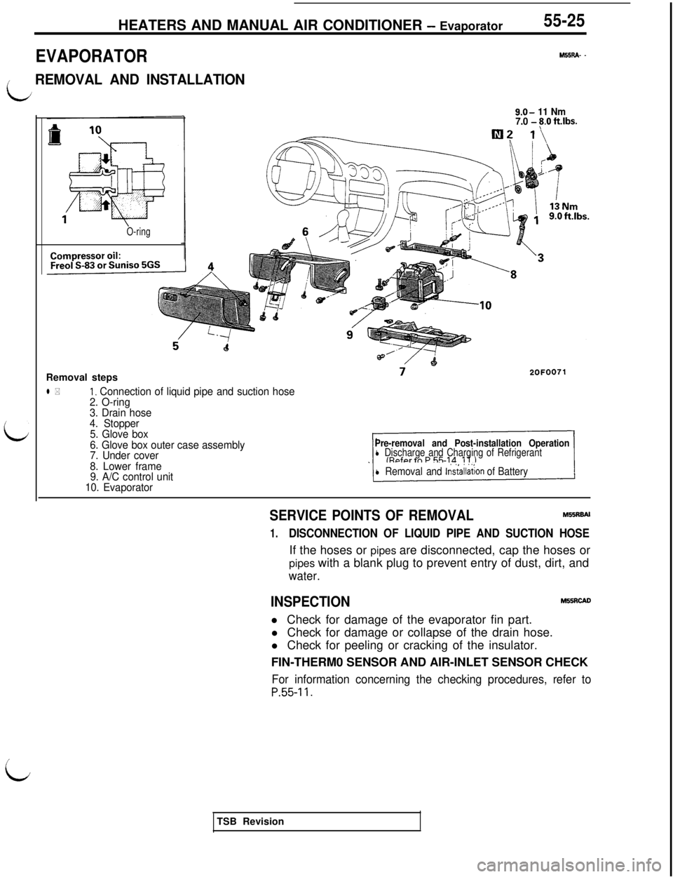
O-ringRemoval steps
l *I, Connection of liquid pipe and suction hose
2. O-ring
3. Drain hose
4. Stopper
5. Glove box
6. Glove box outer case assembly
7. Under cover
8. Lower frame
9. A/C control unit
10. Evaporator
Pre-removal and Post-installation Operationl Discharge and Charging of Refrigerant
l Removal and lns~allation of Battery
SERVICE POINTS OF REMOVALM55RBAl
1.DISCONNECTION OF LIQUID PIPE AND SUCTION HOSEIf the hoses or pipes are disconnected, cap the hoses or
pipes with a blank plug to prevent entry of dust, dirt, and
water.
INSPECTIONM55RcADl Check for damage of the evaporator fin part.
l Check for damage or collapse of the drain hose.
l Check for peeling or cracking of the insulator.
FIN-THERM0 SENSOR AND AIR-INLET SENSOR CHECK
For information concerning the checking procedures, refer to
P.55-11.
iTSB Revision
Page 1109 of 1146
HEATERS AND MANUAL AIR CONDITIONER - Compressor55-27
COMPRESSOR
M55SA- -
/REMOVAL AND INSTALLATION
iJ
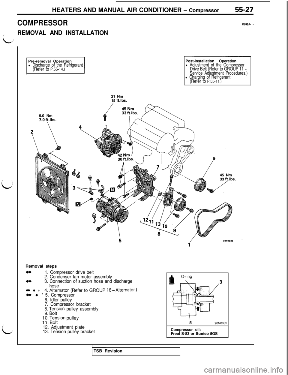
iPre-removal Operation
l Discharge of the Refrigerant(Refer to P.55-14.)9.0 Nm
7.Oft.lbs.
\Post-installation Operation
l Adjustment of the Compressor
Drive Belt (Refer to GROUP 11 -Service Adjustment Procedures.)l Charging of Refrigerant(Refer to P.55-11.)21 Nm
15 ftlbs.Removal steps
a*1. Compressor drive belt
2. Condenser fan motor assembly
4*3. Connection of suction hose and discharge
41) l +4. !%znator (Refer to GROUP l6-Alternator.)*I) l * 5. Compressor
6. Idler pulley
7. Compressor bracket
!I zorr-rion pulley assembly;
;: Fontsion pulley
12. Adjustment plate
13. Tension pulley bracket6
45 Nm
33 ft.lbs.
52ONOO89Compressor oil:
Freol S-83 or Suniso 5GS
TSB Revision