1991 MITSUBISHI 3000GT wheel
[x] Cancel search: wheelPage 869 of 1146

IQ-WHEEL STEERING SYSTEM (4WS) - Control Valve37B-9CONTROL VALVE
Pre-removal Operationl Cleaning of Pipings with Steaml Dratning of Power Steering Fluid(Refer to GROUP 37A - Service Adjustment
Procedures.)
l Removal of Rear Suspension Assembly(Refer to GROUP 34- Rear Suspension Assembly.)
El56I.I
--
iEl7’
1Post-installation Operationl Installation of Rear Suspension Assembly(Refer to GROUP 34 - Rear Suspension Assembly.)l Refillrng and Bleedrng of Power Steering System
(Refer to GROUP 37A-Service AdjustmentProcedures.)l Bleeding of 4WS System(Refer to P.37B-4.)l Checking of 4WS System for Operation
(Refer to P.37B-5.)
M37UA- -
12 Nm
35 Nm24Nm15Nm9 ftlbs.25 ft.lbs.17ft.lbs.
R \
ft.lbs.113012 Nm.\,9ft Ihc
REMOVAL AND INSTALLATION
LRemoval steps
1.Pressure hose2.Pressure tube3.O-ring
4. Pressure tube (RR)
5.O-ring6. Pressure tube (RL)
7.O-ring8. Pressure tube (FL. FR)9.O-ring10.Return pipe11.O-ring
cd
12.Control valve
\35 Nm25 ftlbs.
13FOO25TSB Revision
Page 870 of 1146

37B-10$-WHEEL STEERING SYSTEM (4WS) - Rear Oil Line
REAR OIL LINEM37YFv -
REMOVAL AND INSTALLATION
35 Nm25 ftlbs.
\Removal steps
12 Nm9 ftlbs.
13FOO24
1. Return hose
2. Suction hose
3. Protector
4. Pipe assembly to pressure
tube connection
5. Pipe assembly
6. Suction hose
7. Rubber hose
8. Feed pipe assembly
9. Return pipe assembly
10. Pressure tube assembly to
pipe assembly connection
11. Suction hose
12. Reserve tank
l Cleaning of Pipings with Steam
Post-installation Operationl Refilling and Bleeding of Power Steering System
(Refer to GROUP 37A-Service AdjustmentProcedures.)l Bleeding of 4WS System
(Refer to P.37B-4.)l Checking of 4WS System for Operation
(Refer to P.37B-5.)
INSPECTIONM37YCAnl
Check tubes and pipes for cracking, damage or corrosion.
l
Check hoses for cracking, damage, leakage or fluid seep-
age.l Check flare nuts for damage.
TSB Revision
I
Page 871 of 1146

4-WHEEL STEERING SYSTEM (4WS) - Rear Oil Pump37B-11
REAR OIL PUMP
REMOVAL AND INSTALLATION/
l Draining of Power Steering Fluid
(Refer to GROUP 37A- Service Adjustment
l Removal of Main Muffler Assembly(Refer to GROUP 15 - Exhaust Pipe and Muffler.)
Post-installation Operationl Installation of Main Muffler Assembly(Refer to GROUP 15 - Exhaust Pipe and Muffler.)l Refilling and Bleeding of Power Steering System
(Refer to GROUP 37A- Service AdjustmentProcedures.)l Bleeding of 4WS System
(Refer to P.37B-4.)l Checking of 4WS System for Operation
(Refer to P.37B-5.)
IIO-130Nm80- 94 ft.lbs.Removal steps
1. Rear shock absorber lower mounting bolt4*2. Crossmember bracketa*3. Crossmember mounting nut4.~rry~~,ff~h;t~Jside)
5.Suction hose6. Rear-wheel oil pump7. O-ring80
-94ft.lbs.
13FOO23
NOTEDo not disassemble the rear-wheel oil pump.
M3?MA- -12AOlOS
3
SERVICE POINTS OF REMOVALM37MBAA
2. REMOVAL OF CROSSMEMBER BRACKET / 3. CROSS-MEMBER MOUNTING NUT (ON DIFFERENTIAL SIDE)
(1) Support the differential case with the transmission jack,
then remove the crossmember bracket and crossmem-
ber mounting nut (on the differential side).
(2) Slightly lower the crossmember.
2TSB Revision
Page 889 of 1146

BODY - Service Adjustment Procedures
42-17
I18FOO33
Front floor pan+ Drain plug
lFlFOO91
18FOO9132. If out of specifications, adjust as described below.@ Remove the door trim. (Refer to
P.42-41.)@ Loosen the screw attaching the inside handle and slide
the inside handle back and forth to adjust the inside
handle play.
FLOOR PAN INSPECTIONM42FIADA common result of body leaks is a soaked floor mat pad or
carpet, and it’s not unusual to find that the water is getting in
through the floor pan to some other low point
jn the body. It is
possible however, for water to enter higher up and run
downward to soak the mat.
Since a soaked mat should be removed for drying, it’s a good
way to start your check. Of course, mat removal means you’ll
have to take off door sill plates and pull out seats or seat
cushion. But, this gives you a clear field for action so you can
check body seam sealing and the plugs in the floor pan.
It’s usually not practical to water test for floor pan or
wheelhousing leaks unless a special underbody water spray
arrangement is available. As an alternate, the best way to
locate these leak points is to look for rusty seam edges or other
traces of leaks after the mats and cushions are removed.
Traces of mud are an indication that the water is coming in from
below.
TSB Revision
Page 1012 of 1146

52B-2SUPPLEMENTAL RESTRAINT SYSTEM (SRS) - General informationGENERAL INFORMATION
INTRODUCTIONThe Supplemental Restraint System (SRS) is de-
signed to supplement the driver’s seat belt to help
reduce the risk or severity of injury to the driver by
activating and deploying a driver’s-side air bag in
certain frontal collisions.
The SRS consists of: left front and right front impact
sensors located, one each, on the right and left front
upper frame lowers; an air bag module located in
the center of the steering wheel, which contains the
folded air bag and an inflator unit; the SRS diagnosis
unit located under the rear console assembly, which
monitors the system, and which contains a safing
impact sensor; an SRS warning light located on the
instrument panel, which indicates the operational
status of the SRS; a clock spring interconnection
located within the steering column; system wiring
and wiring connectors; and a knee bolster located
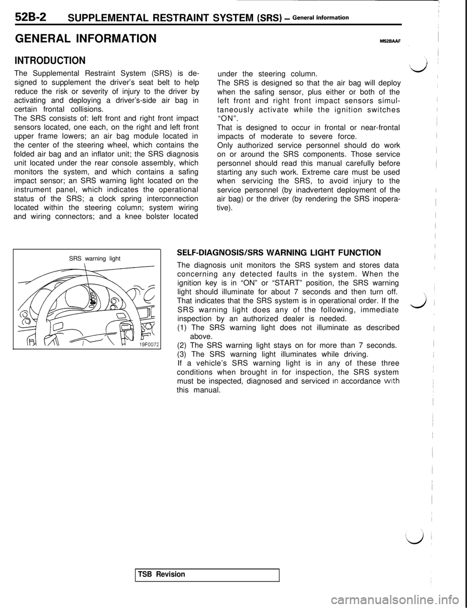
SRS warning light
M52BAAFunder the steering column.
The SRS is designed so that the air bag will deploy
when the safing sensor, plus either or both of the
left front and right front impact sensors simul-
taneously activate while the ignition switches
“ON”.
That is designed to occur in frontal or near-frontal
impacts of moderate to severe force.
Only authorized service personnel should do work
on or around the SRS components. Those service
personnel should read this manual carefully before
starting any such work. Extreme care must be used
whenservicing the SRS, to avoid injury to the
service personnel (by inadvertent deployment of the
air bag) or the driver (by rendering the SRS inopera-
tive).
SELF-DIAGNOSIS/SRS WARNING LIGHT FUNCTION
The diagnosis unit monitors the SRS system and stores data
concerning any detected faults in the system. When the
ignition key is in “ON” or “START” position, the SRS warning
light should illuminate for about 7 seconds and then turn off.
That indicates that the SRS system is in operational order. If the
SRS warning light does any of the following, immediate
inspection by an authorized dealer is needed.
(1) The SRS warning light does not illuminate as described
above.
(2) The SRS warning light stays on for more than 7 seconds.
(3) The SRS warning light illuminates while driving.
If a vehicle’s SRS warning light is in any of these three
conditions when brought in for inspection, the SRS system
must be inspected, diagnosed and serviced
In accordance wrth
this manual.
TSB Revision
Page 1015 of 1146

SUPPLEMENTAL RESTRAINT SYSTEM (SRS) - General lnform=*ion52B-5
r1.c
L
E.
,
iiCAUTION: SRS diagnosis unit
This unit cannot be repaired.
If defective, remove and replace entire unit per
service manual instructions.
Do not disassemble or tamper.
See service manual for handling and storage
instructions.Driver’s air bag information
This vehicle
ha% an air bag which will supple-
ment the driver’s seatbelt in certain frontal
collisions. The air bag is not a substitute for the
driver’s seatbelt in any type of collision. The
driver, and all other occupants, should wear
seatbelts at all times.
WARNING!
If the “SRS” warning light does not come.on
for about 7 seconds when ignition key is turned
to “ON” or engine is started, or if it stays on
while driving, drive the vehicle to your nearest
authorized dealer right away. Also do so if
vehicle’s front end is damaged or if air bag has
deployed.
The air bag system must be inspected by an
authorized dealer ten years after vehicle manu-
facture date shown on certification label lo-
cated on left front door-latch post or door
frame.Read “SRS” section of your owner’s manual
before driving, for important information, about
Dperation, service and disposal of the air bag
svstem.
Do no drop: keep dry.
Failure to follow instructions could render air
bag inoperative and result in driver injury.
F. CAUTION: SRS
Before replacing steering wheel, read service
manual, center front wheels
ahd align SRS
clock spring neutral marks.
Failure to do so may render SRS system
inoperative, risking serious driver injury.
I.
J.WARNING: SRS
This air bag module cannot be repaired. Do not
disassemble or tamper.
Do not perform diagnosis. Do not touch with
electrical test equipment or probes. Refer to
service manual for further instructions, and for
special handling, storage and disposal proce-
dures.
Tampering or mishandling can result in injury.
Danger! Poison. Keep out of the reach of
children.
Contains sodium acid and potassium nitrate
contents are poisonous and extremely flamm-
able. Contact with acid, water, or heavy metals
may produce harmful and irritating gases or
explosive compounds. Do not dismantle, in-
cinerate or bring into contact with electricity or
store at temperatures exceeding
(93.3”C)
200°F.Fast aid: If contents are swallowed induce
vomiting. For eye contact flush eye with water
for 15 minutes. If gases from acid or water
contact are inhaled, seek fresh air. In every
case, get prompt medical attention.
For additional information, see material safety
data sheet (MSDS) for this product.
CAUTION: SRS clock spring
This is not a repairable part. Do not disassem-
ble or tamper.
If defective, remove and replace entire unit per
service manual instructions.
Before replacement, read service manual, cen-
ter front wheels and align neutral marks.
Failure to
foHow instructions may render SRS
system inoperative, risking serious driver in-
jury.CAUTION: SRS
Before removal of steering gearbox, read ser-
vice manual, center front wheels and remove
ignition key.
Failure to do so may damage SRS clock spring
and render SRS system inoperative, risking
serious driver injury.
TSB Revision
Page 1061 of 1146

SRS Maintenance and
SUPPLEMENTAL RESTRAINT SYSTEM (SRS) - Post-coltision Diagnosis 52B-51
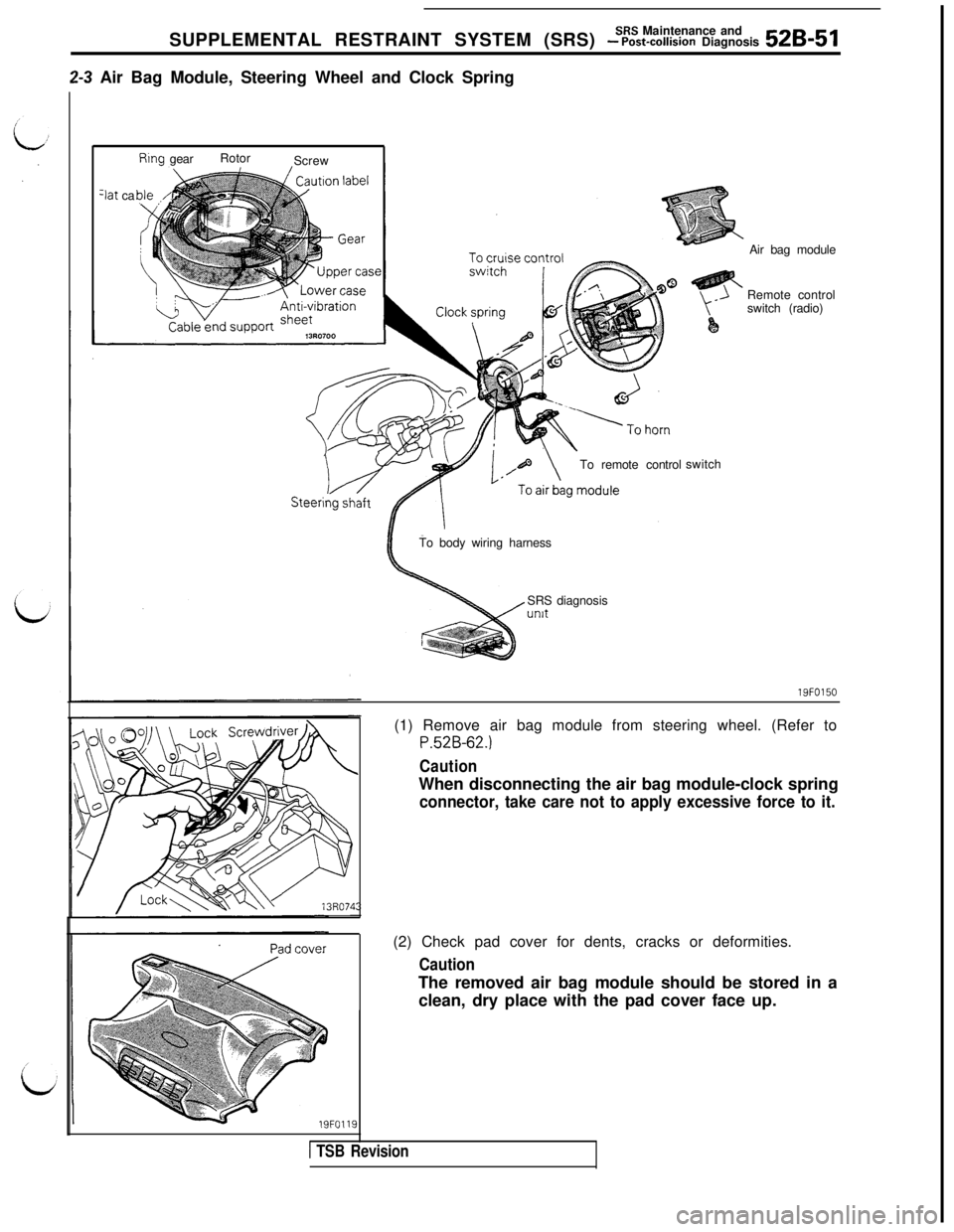
2-3 Air Bag Module, Steering Wheel and Clock Spring
Rtng gearRotor
Screw
3at ca
To remote controlswitchAir bag module
Remote control
switch (radio)
To body wiring harness
SRS diagnosisunit
19FO150
19FO119(1) Remove air bag module from steering wheel. (Refer to
P.52B-62.)
CautionWhen disconnecting the air bag module-clock spring
connector, take care not to apply excessive force to it.(2) Check pad cover for dents, cracks or deformities.
CautionThe removed air bag module should be stored in a
clean, dry place with the pad cover face up.
1 TSB Revision
Page 1062 of 1146

52B-52 SUPPLEMENTAL RESTRAINT SYSTEM fSRSI - ~Z-%~~~~aK&%kTo air bagmodule
To SRS dragnosls unit
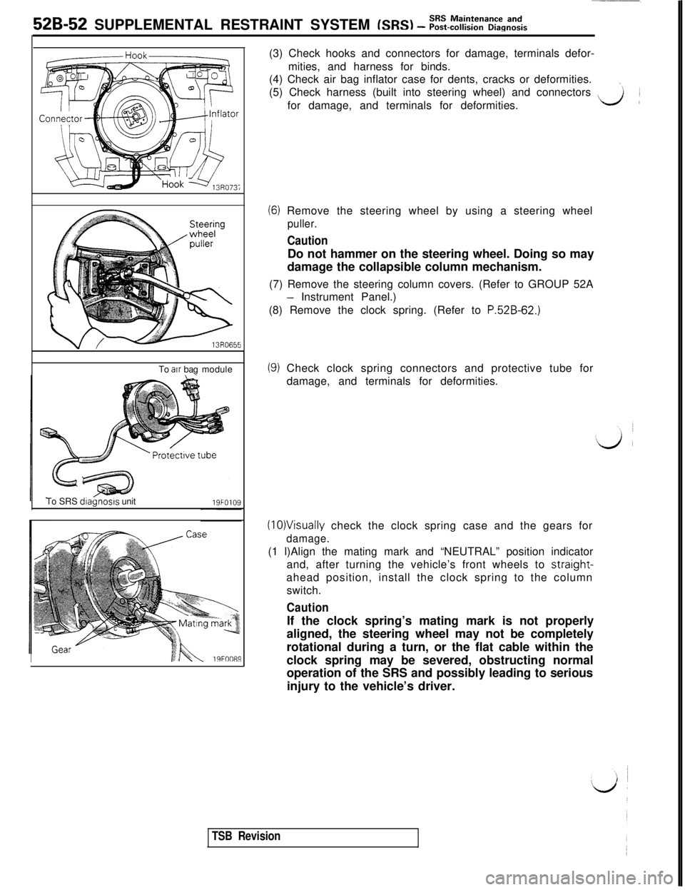
I19FOO89(3) Check hooks and connectors for damage, terminals defor-
mities, and harness for binds.
(4) Check air bag inflator case for dents, cracks or deformities.
\(5) Check harness (built into steering wheel) and connectors
~for damage, and terminals for deformities.LA
(6) Remove the steering wheel by using a steering wheel
puller.
CautionDo not hammer on the steering wheel. Doing so may
damage the collapsible column mechanism.
(7) Remove the steering column covers. (Refer to GROUP 52A
- Instrument Panel.)
(8) Remove the clock spring. (Refer to
P.52B-62.)
(9) Check clock spring connectors and protective tube for
damage, and terminals for deformities.
(10)Visually check the clock spring case and the gears for
damage.(1 l)Align the mating mark and “NEUTRAL” position indicator
and, after turning the vehicle’s front wheels to straight-
ahead position, install the clock spring to the column
switch.
CautionIf the clock spring’s mating mark is not properly
aligned, the steering wheel may not be completely
rotational during a turn, or the flat cable within the
clock spring may be severed, obstructing normal
operation of the SRS and possibly leading to serious
injury to the vehicle’s driver.
TSB Revision