1991 MITSUBISHI 3000GT wheel
[x] Cancel search: wheelPage 1063 of 1146
SRS Maintenance and
SUPPLEMENTAL RESTRAINT SYSTEM (SRS) - Post-collision Diagnosis 52B-53
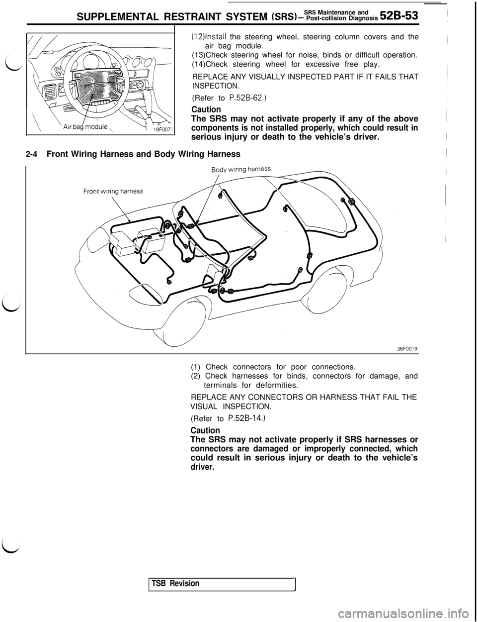
2-4Front Wiring Harness and Body Wiring Harness
(12)lnstall the steering wheel, steering column covers and the
air bag module.
(13)Check steering wheel for noise, binds or difficult operation.
(14)Check steering wheel for excessive free play.
REPLACE ANY VISUALLY INSPECTED PART IF IT FAILS THAT
INSPECTION.(Refer to
P.52B-62.)
CautionThe SRS may not activate properly if any of the above
components is not installed properly, which could result inserious injury or death to the vehicle’s driver.
36FOO19(1) Check connectors for poor connections.
(2) Check harnesses for binds, connectors for damage, and
terminals for deformities.
REPLACE ANY CONNECTORS OR HARNESS THAT FAIL THE
VISUAL INSPECTION.
(Refer to
P.52B-14.)
CautionThe SRS may not activate properly if SRS harnesses or
connectors are damaged or improperly connected, whichcould result in serious injury or death to the vehicle’s
driver.
i
TSB RevisionI
Page 1065 of 1146
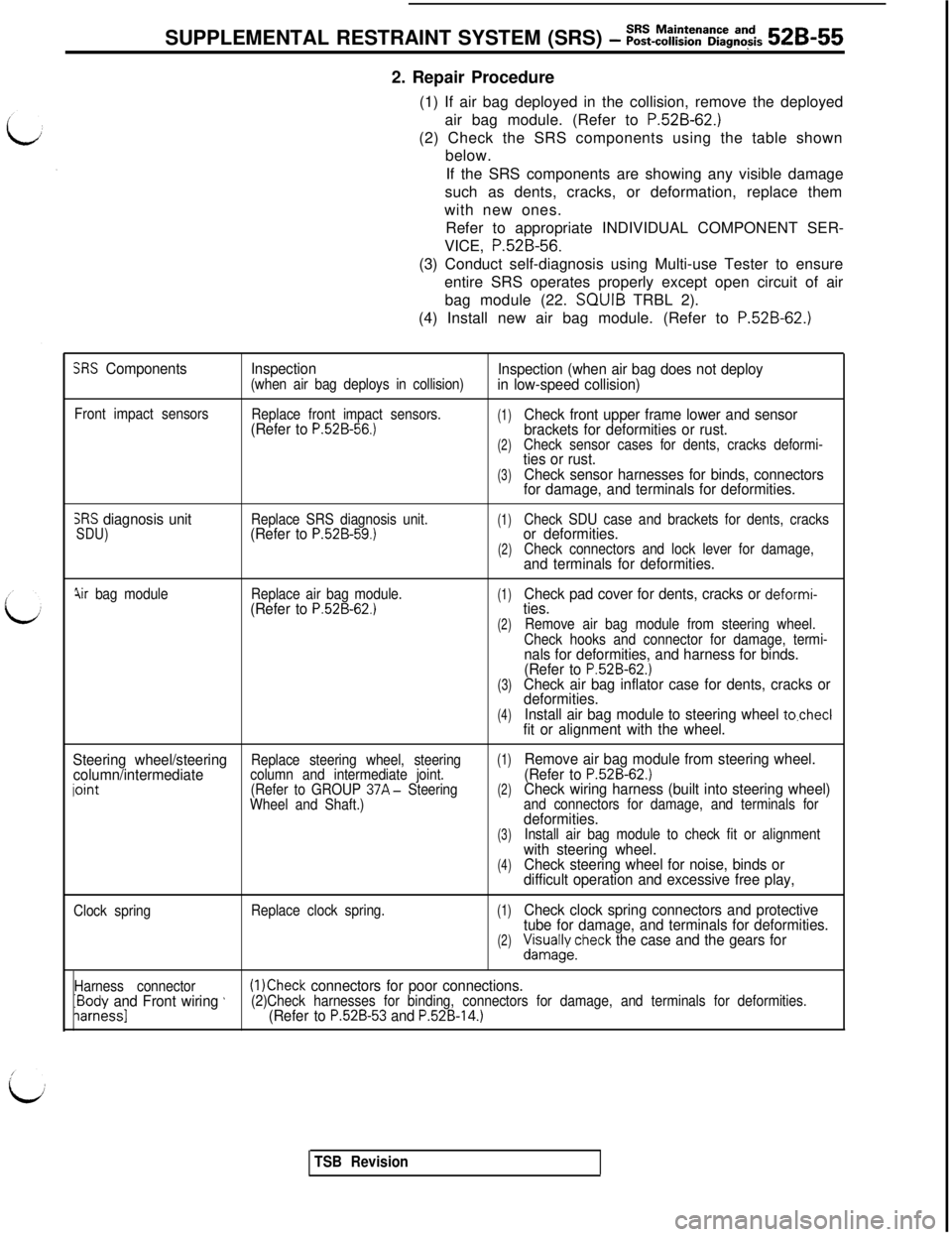
SUPPLEMENTAL RESTRAINT SYSTEM (SRS) - ~~~-~~~~~a~~g~~~s 52B-552. Repair Procedure
(1) If air bag deployed in the collision, remove the deployed
air bag module. (Refer to
P.52B-62.)(2) Check the SRS components using the table shown
below.
If the SRS components are showing any visible damage
such as dents, cracks, or deformation, replace them
with new ones.
Refer to appropriate INDIVIDUAL COMPONENT SER-
VICE, P.52B-56.
(3) Conduct self-diagnosis using Multi-use Tester to ensure
entire SRS operates properly except open circuit of air
bag module (22. SQUIB TRBL 2).
(4) Install new air bag module. (Refer to
P.52B-62.)
SRS ComponentsInspection(when air bag deploys in collision)Inspection (when air bag does not deploy
in low-speed collision)
Front impact sensors
Replace front impact sensors.(Refer to P.52B-56.)(1)Check front upper frame lower and sensor
brackets for deformities or rust.
(2)Check sensor cases for dents, cracks deformi-ties or rust.
(3)Check sensor harnesses for binds, connectors
for damage, and terminals for deformities.
SRS diagnosis unitSDU)Replace SRS diagnosis unit.(Refer to P.52B-59.)(1)Check SDU case and brackets for dents, cracksor deformities.(2)Check connectors and lock lever for damage,and terminals for deformities.
jir bag moduleReplace air bag module.(Refer to P.52B-62.)(1)Check pad cover for dents, cracks or deformi-ties.
(2)Remove air bag module from steering wheel.
Check hooks and connector for damage, termi-
nals for deformities, and harness for binds.
(Refer to P.52B-62.)(3)Check air bag inflator case for dents, cracks or
deformities.
(4)Install air bag module to steering wheel to.checlfit or alignment with the wheel.
Steering wheel/steering
(1)column/intermediateReplace steering wheel, steering
iointcolumn and intermediate joint.Remove air bag module from steering wheel.
(Refer to P.52B-62.)(Refer to GROUP 37A- Steering(2)Wheel and Shaft.)Check wiring harness (built into steering wheel)and connectors for damage, and terminals fordeformities.(3)Install air bag module to check fit or alignmentwith steering wheel.(4)Check steering wheel for noise, binds or
difficult operation and excessive free play,
Clock springReplace clock spring.(1)Check clock spring connectors and protective
tube for damage, and terminals for deformities.
(2)&/;yecheck the case and the gears for
Harness connectorIBody and Front wiring ’(1 )Check connectors for poor connections.
iarnessl(2)Check harnesses for binding, connectors for damage, and terminals for deformities.(Refer to P.52B-53 and P.52B-14.)
TSB Revision
Page 1072 of 1146
52B-62Air Bag ModuleSUPPLEMENTAL RESTRAINT SYSTEM (SRS) - and Clock Spring
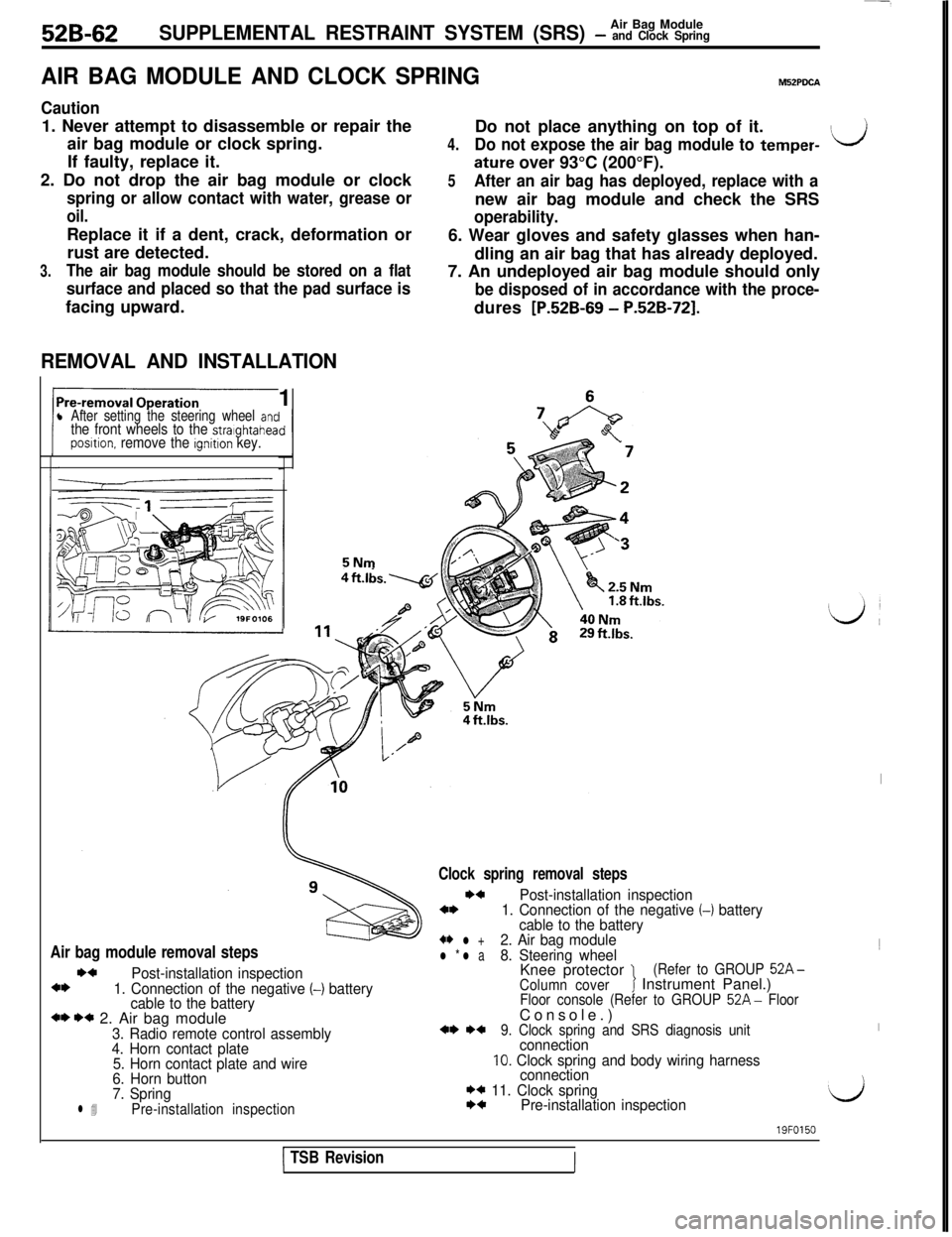
AIR BAG MODULE AND CLOCK SPRINGM52PDCA
Caution1. Never attempt to disassemble or repair the
air bag module or clock spring.
If faulty, replace it.
2. Do not drop the air bag module or clock
spring or allow contact with water, grease or
oil.Replace it if a dent, crack, deformation or
rust are detected.
3.The air bag module should be stored on a flat
surface and placed so that the pad surface isfacing upward.
REMOVAL AND INSTALLATION1
l After setting the steering wheel antthe front wheels to the stralghtaheaposltion. remove the ignition key.5NmDo not place anything on top of it.
4.Do not expose the air bag module to temper-ILJ
ature over 93°C (200°F).
5After an air bag has deployed, replace with anew air bag module and check the SRS
operability.6. Wear gloves and safety glasses when han-
dling an air bag that has already deployed.
7. An undeployed air bag module should only
be disposed of in accordance with the proce-dures
[P.52B-69 - P.52B-721.
Air bag module removal stepsI)4
Post-installation inspection4*1. Connection of the negative (-1 battery
cable to the battery
*I) I)* 2. Air bag module3. Radio remote control assembly
4. Horn contact plate
5. Horn contact plate and wire
6. Horn button
7. Spring
l 4Pre-installation inspection
Clock spring removal steps
I)4Post-installation inspection4*1. Connection of the negative (-1 battery
cable to the battery
+* l +2. Air bag modulel * l a8. Steering wheelKnee protector 1(Refer to GROUP 52A-
Column coverJ Instrument Panel.)Floor console (Refer to GROUP 52A- FloorConsole.)
*I) *+9. Clock spring and SRS diagnosis unitconnection10. Clock spring and body wiring harness
connection
I)* 11. Clock springI)4Pre-installation inspection
I1
I
‘d
1 TSB Revision
19FO150
III
Page 1073 of 1146
Air Bag ModuleSUPPLEMENTAL RESTRAINT SYSTEM (SRS) - and Clock Spring526-6319FOlll
3
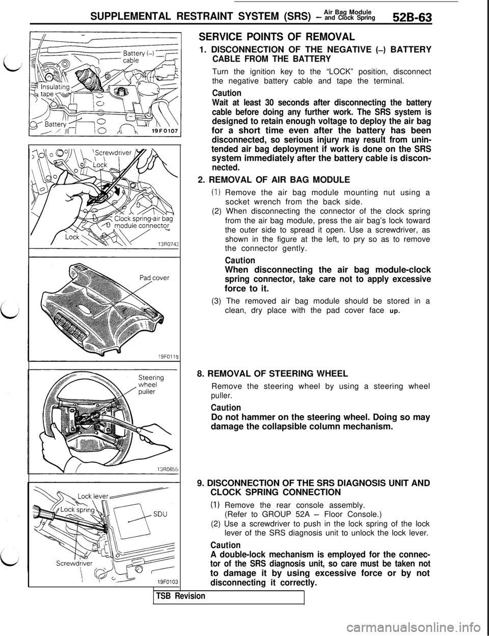
SERVICE POINTS OF REMOVAL1. DISCONNECTION OF THE NEGATIVE (-) BATTERY
CABLE FROM THE BATTERYTurn the ignition key to the “LOCK” position, disconnect
the negative battery cable and tape the terminal.
Caution
Wait at least 30 seconds after disconnecting the battery
cable before doing any further work. The SRS system is
designed to retain enough voltage to deploy the air bagfor a short time even after the battery has been
disconnected, so serious injury may result from unin-
tended air bag deployment if work is done on the SRSsystem immediately after the battery cable is discon-
nected.2. REMOVAL OF AIR BAG MODULE
(1) Remove the air bag module mounting nut using a
socket wrench from the back side.
(2) When disconnecting the connector of the clock spring
from the air bag module, press the air bag’s lock toward
the outer side to spread it open. Use a screwdriver, as
shown in the figure at the left, to pry so as to remove
the connector gently.
CautionWhen disconnecting the air bag module-clock
spring connector, take care not to apply excessiveforce to it.
(3) The removed air bag module should be stored in a
clean, dry place with the pad cover face up.
8. REMOVAL OF STEERING WHEEL
Remove the steering wheel by using a steering wheel
puller.
CautionDo not hammer on the steering wheel. Doing so may
damage the collapsible column mechanism.
9. DISCONNECTION OF THE SRS DIAGNOSIS UNIT AND
CLOCK SPRING CONNECTION
(1) Remove the rear console assembly.
(Refer to GROUP 52A
- Floor Console.)
(2) Use a screwdriver to push in the lock spring of the lock
lever of the SRS diagnosis unit to unlock the lock lever.
Caution
A double-lock mechanism is employed for the connec-
tor of the SRS diagnosis unit, so care must be taken notto damage it by using excessive force or by not
disconnecting it correctly.
TSB Revision
Page 1074 of 1146
52B-64Air Eag Module
SUPPLEMENTAL RESTRAINT SYSTEM (SRS) - and Clock SpringConnector note
\\ I,
13R072113R0722
Air
b\“g module \(3) Remove the
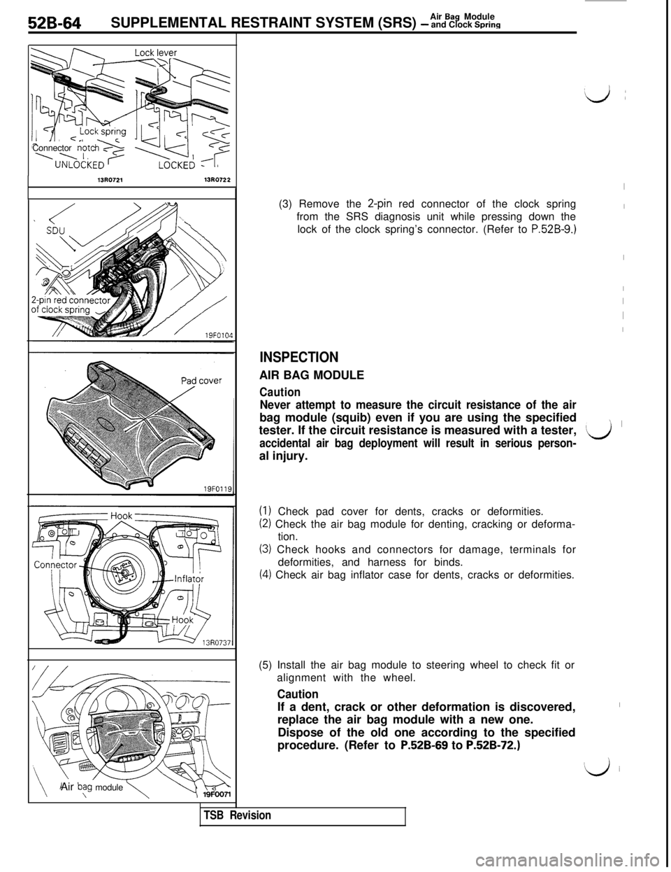
2-pin red connector of the clock spring
from the SRS diagnosis unit while pressing down the
lock of the clock spring’s connector. (Refer to
P.52B-9.)
INSPECTIONAIR BAG MODULE
Caution
Never attempt to measure the circuit resistance of the airbag module (squib) even if you are using the specified
tester. If the circuit resistance is measured with a tester,
accidental air bag deployment will result in serious person-al injury.
(1) Check pad cover for dents, cracks or deformities.
(2) Check the air bag module for denting, cracking or deforma-
tion.
(3) Check hooks and connectors for damage, terminals for
deformities, and harness for binds.
(4) Check air bag inflator case for dents, cracks or deformities.
TSB Revision(5) Install the air bag module to steering wheel to check fit or
alignment with the wheel.
CautionIf a dent, crack or other deformation is discovered,
replace the air bag module with a new one.
Dispose of the old one according to the specified
procedure. (Refer to
P52B-69 to P.52B-72.)
I
I
I
I
I
I
I
’ I
‘Lj
I
‘iJ i
Page 1077 of 1146
Air Bag Module
SUPPLEMENTAL RESTRAINT SYSTEM (SRS) - and Clock Spring52B-67Multi-use Testkr
ROM pack
(MB991 341)(MB991 359)
Diagnosis/
service
data
oumutGround
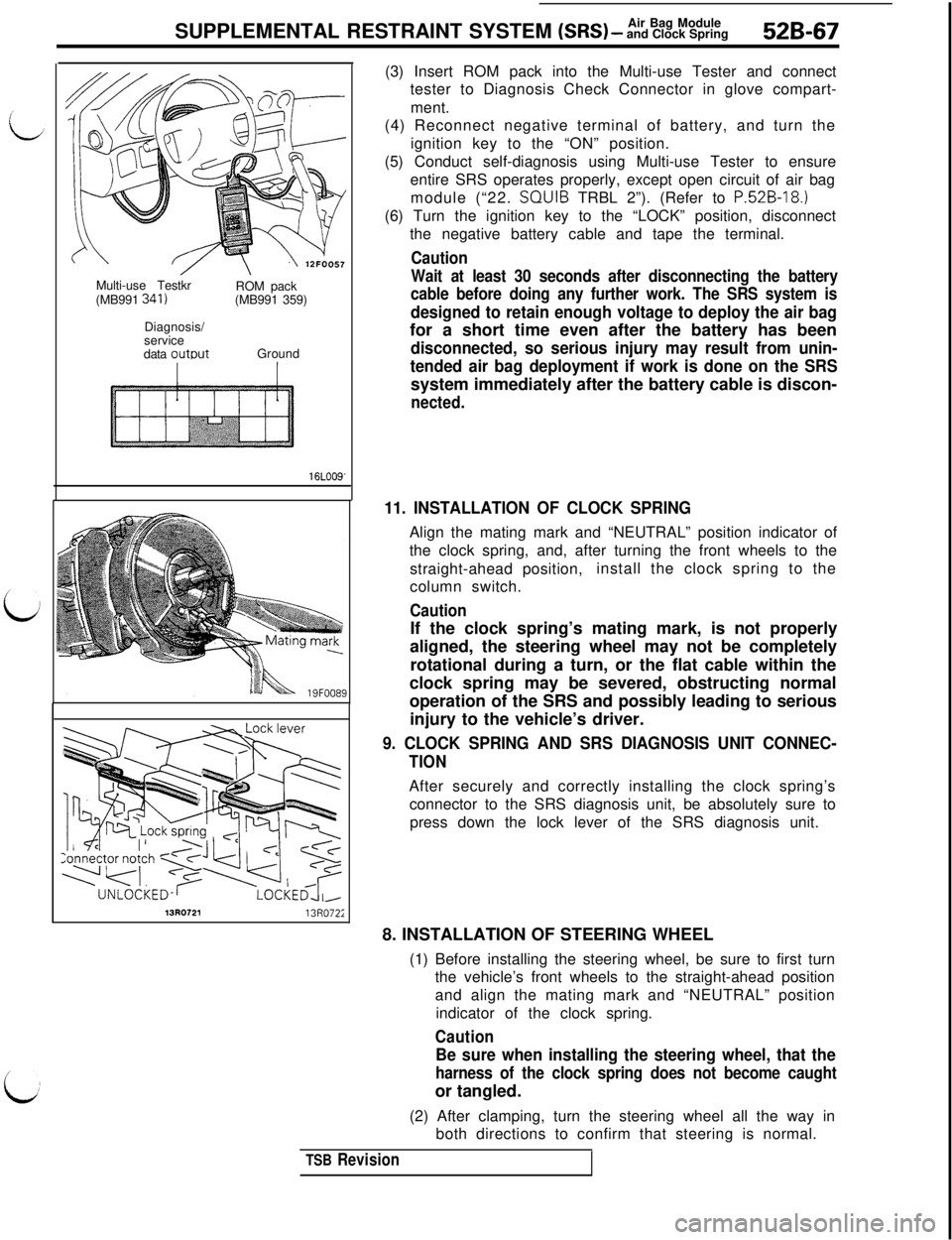
16LOO9'(3) Insert ROM pack into the Multi-use Tester and connect
tester to Diagnosis Check Connector in glove compart-
ment.
(4) Reconnect negative terminal of battery, and turn the
ignition key to the “ON” position.
(5) Conduct self-diagnosis using Multi-use Tester to ensure
entire SRS operates properly, except open circuit of air bag
module (“22. SQUIB TRBL 2”). (Refer to
P.52B-18.)(6) Turn the ignition key to the “LOCK” position, disconnect
the negative battery cable and tape the terminal.
Caution
Wait at least 30 seconds after disconnecting the battery
cable before doing any further work. The SRS system is
designed to retain enough voltage to deploy the air bagfor a short time even after the battery has been
disconnected, so serious injury may result from unin-
tended air bag deployment if work is done on the SRSsystem immediately after the battery cable is discon-
nected.
11. INSTALLATION OF CLOCK SPRINGAlign the mating mark and “NEUTRAL” position indicator of
the clock spring, and, after turning the front wheels to the
straight-ahead position,install the clock spring to the
column switch.
CautionIf the clock spring’s mating mark, is not properly
aligned, the steering wheel may not be completely
rotational during a turn, or the flat cable within the
clock spring may be severed, obstructing normal
operation of the SRS and possibly leading to serious
injury to the vehicle’s driver.
9. CLOCK SPRING AND SRS DIAGNOSIS UNIT CONNEC-
TIONAfter securely and correctly installing the clock spring’s
connector to the SRS diagnosis unit, be absolutely sure to
press down the lock lever of the SRS diagnosis unit.
13R072113R072;8. INSTALLATION OF STEERING WHEEL
(1) Before installing the steering wheel, be sure to first turn
the vehicle’s front wheels to the straight-ahead position
and align the mating mark and “NEUTRAL” position
indicator of the clock spring.
Caution
Be sure when installing the steering wheel, that the
harness of the clock spring does not become caughtor tangled.
(2) After clamping, turn the steering wheel all the way in
both directions to confirm that steering is normal.
TSB Revision
Page 1078 of 1146
52B-68SUPPLEMENTAL RESTRAINT SYSTEM (SRS) - %%%$kgSRS warning
light
/------ r--l
I
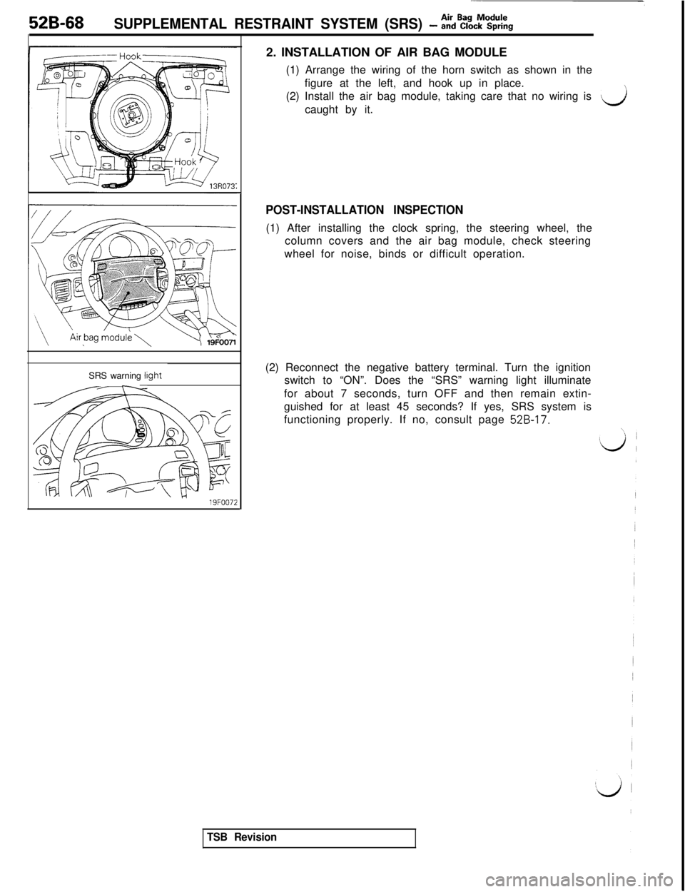
19FOO722. INSTALLATION OF AIR BAG MODULE
(1) Arrange the wiring of the horn switch as shown in the
figure at the left, and hook up in place.
(2) Install the air bag module, taking care that no wiring is
vicaught by it.
POST-INSTALLATION INSPECTION(1) After installing the clock spring, the steering wheel, the
column covers and the air bag module, check steering
wheel for noise, binds or difficult operation.
(2) Reconnect the negative battery terminal. Turn the ignition
switch to “ON”. Does the “SRS” warning light illuminate
for about 7 seconds, turn OFF and then remain extin-
guished for at least 45 seconds? If yes, SRS system is
functioning properly. If no, consult page
52B-17.
TSB Revision
Page 1099 of 1146
HEATERS AND MANUAL AIR CbNDlTlONER -Service Adjustment Procedures 55 17
ADJUSTMENT PROCEDURES(1) Select a quiet area for testing. Duplicate conditions as much
as possible. Switch compressor on and off several times to
clearly identify compressor noise.
To duplicate high ambient conditions (high head pressure),
restrict air flow through condenser. Install manifold gauge
set to make sure discharge pressure doesn’t exceed 2,070
kPa (300 psi).
(2) Tighten all compressor mounting bolts, clutch mounting
bolt, and compressor drive belt. Check to assure clutch coil
is tight (no rotation or wobble).
(3) Check refrigerant hoses for rubbing or interference that can
cause unusual noises.
(4) Check refrigerant charge. (See “Charging System”.)
(5) Recheck compressor noise as in Step 1.
(6) If noise still exists, loosen compressor mounting bolts and
retorque. Repeat Step 1.
(7) If noise continues, replace compressor and repeat Step 1.
POWER RELAY CHECKMBBFNAK(1) Remove the radiator fan motor relays (HI) and (LO) from the
relay box on the right of the engine compartment.
(2) Remove the radiator fan motor relay (air conditioner),
condenser fan motor relays (HI) and (LO), and
air-conditioner compressor relay from the relay box on the left
of the engine compartment.
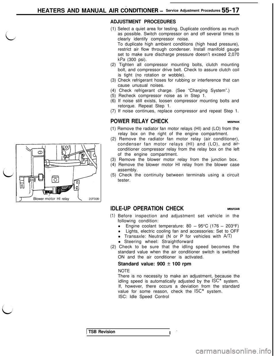
(3) Remove the blower motor relay from the junction box.
(4) Remove the blower motor HI relay from the blower case
assembly.
(5) Check the continuity between terminals using a circuit
tester.
J Blower m.otor HI relay\2OFOO6l
IDLE-UP OPERATION CHECKM55FOAB
(1) Before inspection and adjustment set vehicle in the
following condition:
lEngine coolant temperature: 80 - 95°C (176 - 203°F)
lLights, electric cooling fan and accessories: Set to OFF
l Transaxle: Neutral (N or P for vehicles with
A/T)l Steering wheel: Straightforward
(2) Check to be sure that the idling speed becomes the
standard value when the air conditioner switch is switched
ON and the air conditioner is activated.
Standard value: 900
+ 100 rpm
NOTEThere is no necessity to make an adjustment, because the
idling speed is automatically adjusted by the ISC” system.
If, however, there occurs a deviation from the standard
value for some reason, check the ISC” system.
ISC: Idle Speed Control
1 TSB RevisionI -