1991 MITSUBISHI 3000GT flat tire
[x] Cancel search: flat tirePage 639 of 1146

31-1
ii~
WHEEL.I
AND TIRE~
CONTENTSM3IA& -
SERVICE ADJUSTMENT PROCEDURES............4TROUBLESHOOTING:...........................................3
Tire Inflation Pressure Check................................4Bald Spots
Tire Wear Check....................................................4
Cracked Treads
Wheel Runout Check............................................4Feathered Edge
SPECIFICATIONS2Rapid Wear at Center....................................................
General Specifications2Rapid Wear at Shoulders........................................
Service Specifications........................................2Scalloped Wear
Torque Specifications2Wear on One Side............................................
Page 640 of 1146

31-2WHEEL AND TIRE - Specifications
SPECIFICATIONS
GENERAL SPECIFICATIONS
MOICA- -
‘\
Items
Wheel
Tire size
Wheel type
Wheel size
Amount of wheel offsetmm (in.)
Tire inflation pressure
kPa (psi)
Front
Rear
DOHC-N/A
225l55R 16 93U
Aluminum type
16X8J ’
46 (1.8)
220 (32)
200 (29)DOHC-T/C
245145ZR 17
Aluminum type
17 x
8.5J
46 (1.8)
220 (32)
200 (29)
Spare wheel
Tire size
T125190D16T135/90D16
Wheel size
l6x4Tl6x4T
Amount of wheel offsetmm (in.)46 (1.8)46 (1.8)
Tire inflation pressurekPa (psi)
420 (60)420 (60)
SERVICE SPECIFICATIONSM31CB. -
Items
Specifications
Limit
Wheel
runout
Radialmm (in.)2.0 (.08)
Lateralmm (in.)2.0 t.08)
Tread depth of tiremm (in.)1.6 (.06)
TORQUE SPECIFICATIONSMBlCC- -
ItemsNm
Hub nuts120- 140
ft.lbs.
87-iO1TSB Revision
Page 641 of 1146

WHEEL AND TIRE - Troubleshooting.TROUBLESHOOTING
M31EAAB
at center
Over-inflation orlack of rotation
Inspect the camber
Adjust the unbalanced wheels
weare front suspensionTSB Revision
Page 642 of 1146

WHEEL AND TIRE - Service Adiustment ProceduresllFOO1753Y510
Wear indicator
/LateralllFOO1:
1SERVICE ADJUSTMENT PROCEDURES
TIRE INFLATION PRESSURE CHECKM3lFDA.E
Check the inflation pressure of the tires. If it is not within the
standard value, make the necessary adjustment.
TIRE WEAR CHECKMJlFBAC
Measure the tread depth of tires.
Limit: 1.6 mm
(.06 in.)
If the remaining tread depth is less than the limit, replace the
tire.
NOTE
When the tread depth of tire is reduced to 1.6 mm (.06 in.) orless, wear indicator will appear.
WHEEL RUNOUT CHECKM31 FCAEJack up the vehicle so that the wheels are clear of the floor.
While slowly turning the wheel, measure wheel runout with a
dial indicator.
Limit:
Radial2.0 mm
(.08 in.)
Lateral2.0 mm (.08 in.)
If wheel
runout exceeds the limit, replace the wheel.
TSB Revision
Page 653 of 1146

FRONT SUSPENSION - Special Tools / Troubleshooting
SPECIAL TOOLS
L
L
Removalof the lower arm ball joint and
Wheel alignment
gauge attachment
Measurement of the wheel alignment
Spring compressorCompression of the front coil spring
MB990799-01Ball joint remover
and installerInstallation of the dust shield
TROUBLESHOOTINGM33EBAA
SymptomProbable causeRemedy
Steering wheel is heavy,Suspension malfunctionvibrates or pulls toBall joint
Adjust orreplace
one sideCoil springWheel alignment
Unbalanced or worn tiresAdjust or replace
Excessive vehicleBroken or deteriorated stabilizer
rollingShock absorber malfunctionReplace
Poor ridingImproper tire inflation pressureAdjust
Broken or deteriorated coil spring
Shock absorber malfunctionReplace
Inclination of vehicleBroken or deteriorated coil springReplace
NoiseLack of lubricationLubricate
Looseness and wear of each partRetighten or replace
Broken coil spring
Shock absorber malfunction
ReplaceTSB Revision
I
Page 690 of 1146

34-4REAR SUSPENSION
TROUBLESHOOTING
Symptom
Squeaks or other
abnormal noiseProbable cause
Loose rear suspension installation bolts and nuts
Malfunction of shock absorber
Worn bushings
Upper arms
and/or lower arms and/or assistlink deformed or damaged
Trailing arms deformed or damaged
Crossmember deformed or damaged
Excessive tire inflation pressure
Malfunction of shock absorber
Weakpr broken springs
Stabilizer bar and/or stabilizer link deformed
or damaged
Weak or deteriorated bushingsWeak or broken springs
Upper arms and/or lower arms and/or assistlink deformed or damaged
Trailing arms deformed or damaged
Crossmember deformed or damagedRemedy
Retrghten
Replace
Poor ride
Body tiltingAdjust the pressure
Replace
Replace
TSB Revision
Page 1065 of 1146

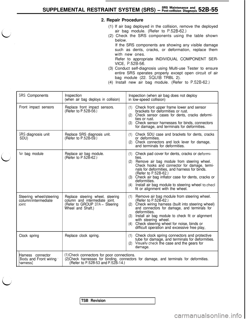
SUPPLEMENTAL RESTRAINT SYSTEM (SRS) - ~~~-~~~~~a~~g~~~s 52B-552. Repair Procedure
(1) If air bag deployed in the collision, remove the deployed
air bag module. (Refer to
P.52B-62.)(2) Check the SRS components using the table shown
below.
If the SRS components are showing any visible damage
such as dents, cracks, or deformation, replace them
with new ones.
Refer to appropriate INDIVIDUAL COMPONENT SER-
VICE, P.52B-56.
(3) Conduct self-diagnosis using Multi-use Tester to ensure
entire SRS operates properly except open circuit of air
bag module (22. SQUIB TRBL 2).
(4) Install new air bag module. (Refer to
P.52B-62.)
SRS ComponentsInspection(when air bag deploys in collision)Inspection (when air bag does not deploy
in low-speed collision)
Front impact sensors
Replace front impact sensors.(Refer to P.52B-56.)(1)Check front upper frame lower and sensor
brackets for deformities or rust.
(2)Check sensor cases for dents, cracks deformi-ties or rust.
(3)Check sensor harnesses for binds, connectors
for damage, and terminals for deformities.
SRS diagnosis unitSDU)Replace SRS diagnosis unit.(Refer to P.52B-59.)(1)Check SDU case and brackets for dents, cracksor deformities.(2)Check connectors and lock lever for damage,and terminals for deformities.
jir bag moduleReplace air bag module.(Refer to P.52B-62.)(1)Check pad cover for dents, cracks or deformi-ties.
(2)Remove air bag module from steering wheel.
Check hooks and connector for damage, termi-
nals for deformities, and harness for binds.
(Refer to P.52B-62.)(3)Check air bag inflator case for dents, cracks or
deformities.
(4)Install air bag module to steering wheel to.checlfit or alignment with the wheel.
Steering wheel/steering
(1)column/intermediateReplace steering wheel, steering
iointcolumn and intermediate joint.Remove air bag module from steering wheel.
(Refer to P.52B-62.)(Refer to GROUP 37A- Steering(2)Wheel and Shaft.)Check wiring harness (built into steering wheel)and connectors for damage, and terminals fordeformities.(3)Install air bag module to check fit or alignmentwith steering wheel.(4)Check steering wheel for noise, binds or
difficult operation and excessive free play,
Clock springReplace clock spring.(1)Check clock spring connectors and protective
tube for damage, and terminals for deformities.
(2)&/;yecheck the case and the gears for
Harness connectorIBody and Front wiring ’(1 )Check connectors for poor connections.
iarnessl(2)Check harnesses for binding, connectors for damage, and terminals for deformities.(Refer to P.52B-53 and P.52B-14.)
TSB Revision
Page 1077 of 1146

Air Bag Module
SUPPLEMENTAL RESTRAINT SYSTEM (SRS) - and Clock Spring52B-67Multi-use Testkr
ROM pack
(MB991 341)(MB991 359)
Diagnosis/
service
data
oumutGround
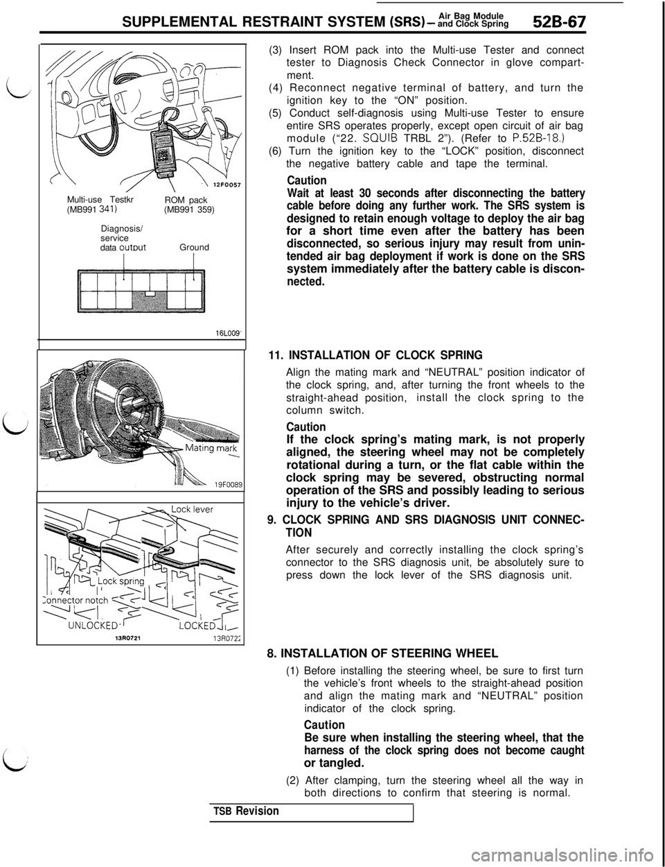
16LOO9'(3) Insert ROM pack into the Multi-use Tester and connect
tester to Diagnosis Check Connector in glove compart-
ment.
(4) Reconnect negative terminal of battery, and turn the
ignition key to the “ON” position.
(5) Conduct self-diagnosis using Multi-use Tester to ensure
entire SRS operates properly, except open circuit of air bag
module (“22. SQUIB TRBL 2”). (Refer to
P.52B-18.)(6) Turn the ignition key to the “LOCK” position, disconnect
the negative battery cable and tape the terminal.
Caution
Wait at least 30 seconds after disconnecting the battery
cable before doing any further work. The SRS system is
designed to retain enough voltage to deploy the air bagfor a short time even after the battery has been
disconnected, so serious injury may result from unin-
tended air bag deployment if work is done on the SRSsystem immediately after the battery cable is discon-
nected.
11. INSTALLATION OF CLOCK SPRINGAlign the mating mark and “NEUTRAL” position indicator of
the clock spring, and, after turning the front wheels to the
straight-ahead position,install the clock spring to the
column switch.
CautionIf the clock spring’s mating mark, is not properly
aligned, the steering wheel may not be completely
rotational during a turn, or the flat cable within the
clock spring may be severed, obstructing normal
operation of the SRS and possibly leading to serious
injury to the vehicle’s driver.
9. CLOCK SPRING AND SRS DIAGNOSIS UNIT CONNEC-
TIONAfter securely and correctly installing the clock spring’s
connector to the SRS diagnosis unit, be absolutely sure to
press down the lock lever of the SRS diagnosis unit.
13R072113R072;8. INSTALLATION OF STEERING WHEEL
(1) Before installing the steering wheel, be sure to first turn
the vehicle’s front wheels to the straight-ahead position
and align the mating mark and “NEUTRAL” position
indicator of the clock spring.
Caution
Be sure when installing the steering wheel, that the
harness of the clock spring does not become caughtor tangled.
(2) After clamping, turn the steering wheel all the way in
both directions to confirm that steering is normal.
TSB Revision