Page 1101 of 1146

HEATERS AND MANUAL AIR CONDITIONER - Heater cmrol *=mW55-19
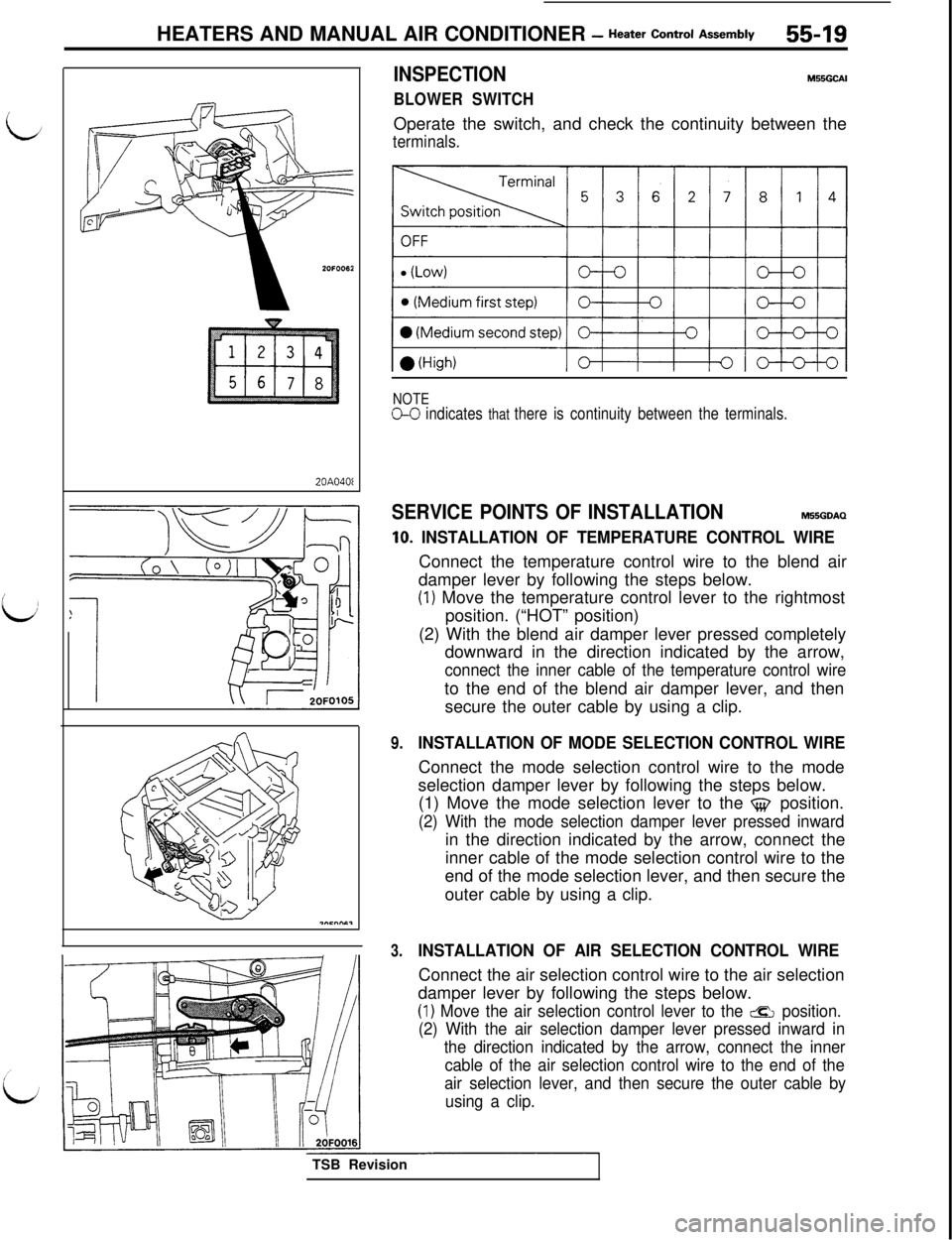
20A040fINSPECTION
BLOWER SWITCH
M55GCAIOperate the switch, and check the continuity between the
terminals.
NOTEo-0 indicates that there is continuity between the terminals.
SERVICE POINTS OF INSTALLATIONM55GDAQ
10. INSTALLATION OF TEMPERATURE CONTROL WIREConnect the temperature control wire to the blend air
damper lever by following the steps below.
(1) Move the temperature control lever to the rightmost
position. (“HOT” position)
(2) With the blend air damper lever pressed completely
downward in the direction indicated by the arrow,
connect the inner cable of the temperature control wireto the end of the blend air damper lever, and then
secure the outer cable by using a clip.
9.INSTALLATION OF MODE SELECTION CONTROL WIREConnect the mode selection control wire to the mode
selection damper lever by following the steps below.
(1) Move the mode selection lever to the
$$ position.
(2) With the mode selection damper lever pressed inwardin the direction indicated by the arrow, connect the
inner cable of the mode selection control wire to the
end of the mode selection lever, and then secure the
outer cable by using a clip.
3.INSTALLATION OF AIR SELECTION CONTROL WIREConnect the air selection control wire to the air selection
damper lever by following the steps below.
(1) Move the air selection control lever to the &ZI position.
(2) With the air selection damper lever pressed inward in
the direction indicated by the arrow, connect the inner
cable of the air selection control wire to the end of the
air selection lever, and then secure the outer cable by
using a clip.TSB Revision
Page 1102 of 1146
55-20 HEATERS AND MANUAL AIR CONDlTlONER - Resistor, Belt Lock Controller
RESISTOR, BELT LOCK CONTROLLERM55JA- -
REMOVAL AND INSTALLATION
viRemoval steps
1. Stoooer
2OFOO732. Globk box outer case assembly
3. Resistor
4. Under cover
5. Belt lock controller
- 2OPOOl
I--TSB I
INSPECTION
RESISTOR CHECK
hl55JCADUsing a circuit tester, measure the resistance between the
terminals indicated below.
The condition can be considered satisfactory if the value
measured at this time is equivalent to the standard value.
Standard value
Terminals measuredStandard value fi
Between terminals a-- @Approx. 1.79 - 2.06
Between terminals
@ -@Approx. 1 .I 0 - 1.26
Between terminals @ - @Approx. 0.38 - 0.44vision
Page 1103 of 1146
HEATERS AND MANUAL AIR CONDITIONER - Air Condikner Switch55-21
AIR CONDITIONER SWITCH
L
REMOVAL AND INSTALLATIONRemoval steps
1. Center air outlet assembly
2. Air conditioner switch
II/J2OFOO95
M55QA- *
1
I I\L!Y,“~ s/
//
L/
l-----L-I
SERVICE POINTS OF REMOVALM55QBAH1. REMOVAL OF CENTER AIR OUTLET ASSEMBLY
Disengaging the clips (2 positions) of the center air outlet
assembly with a flat tip screwdriver, remove the center airoutlet assembly with the trim stick.
2. REMOVAL OF AIR CONDITIONER SWITCH
Remove the center air outlet assembly, and insert hand tothe back of the cluster panel assembly through the
produced opening. Push it toward you for removal.
INSPECTION
AIR CONDITIONER SWITCH CHECKM55QCAD
OFF.
0
light
If pressed 1 step (ECONOMY)
If pressed 2 steps(Air conditioner)
NOTE(1) The O-O symbol indicates continuity(2) *: 20A018ITSB Revision
Page 1104 of 1146

55-22HEATERS AND MANUAL AIR CONDITIONER - Heater Unit
HEATER UNIT
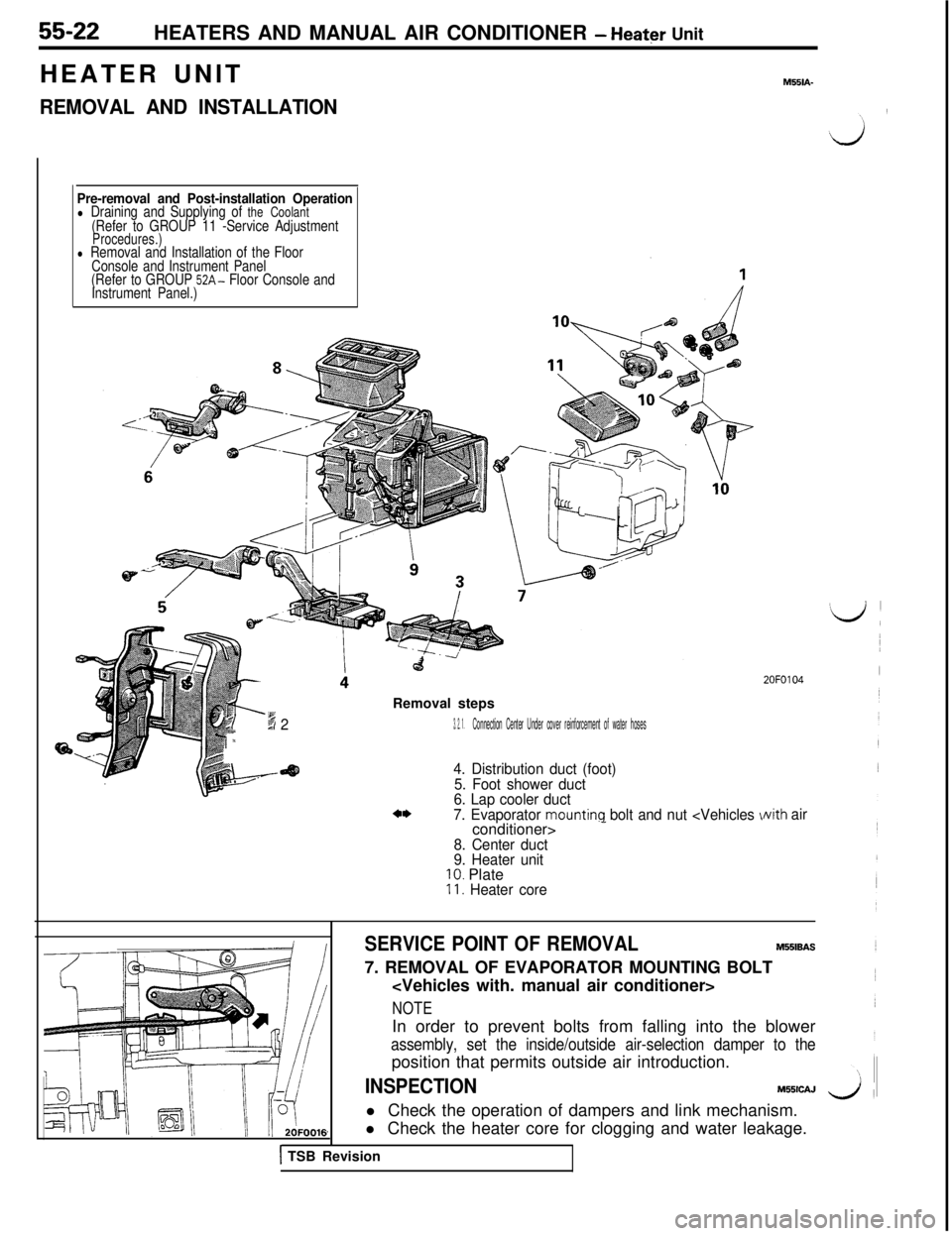
REMOVAL AND INSTALLATION
M551A-
Pre-removal and Post-installation Operationl Draining and Supplying of the Coolant(Refer to GROUP 11 -Service AdjustmentProcedures.)l Removal and Installation of the Floor
Console and Instrument Panel
(Refer to GROUP
52A- Floor Console and
Instrument Panel.)Removal steps
-6 dx23. 2. 1.Connection Center Under cover reinforcement of water hoses
4. Distribution duct (foot)
5. Foot shower duct
6. Lap cooler duct
7. Evaporator
mounting bolt and nut -
8. Center duct
9. Heater unit
10. Plate11. Heater core
2OFO104
Nith air
SERVICE POINT OF REMOVALM551BAS7. REMOVAL OF EVAPORATOR MOUNTING BOLT
NOTEIn order to prevent bolts from falling into the blower
assembly, set the inside/outside air-selection damper to theposition that permits outside air introduction.
INSPECTIONM55lCAJ
l Check the operation of dampers and link mechanism.
l Check the heater core for clogging and water leakage.
1 TSB Revision
Page 1105 of 1146
HEATERS AND MANUAL AIR CONDITIONER - Blower Assembly55-23
BLOWER ASSEMBLY
M55KA- _
/REMOVAL ANDINSTALLATION2OFOO79
Removal steps of blower case assembly
1. Stopper
2. Glove box
3. Glove box outer
case assembly
4. Under cover
5. Lower frame
6. Evaporator mounting bolt and nut
l a7. Connection of the air-selection wire
8. Side frame
9. Blower assembly
*+ 10. Blower motor assembly11. Blower case assemblyRemoval steps of blower
motor assembly
4. Under coverl * 10. Blower motor assemblyTSB Revision
Page 1106 of 1146

55-24
IHEATERS AND MANUAL AIR CONDITIONER
- Blower Assembly
INSPECTIONM55KCAMl Check for bending or abnormal deflection of the rotating
Ishaft of the blower motor assembly.
l Check for cracking or deterioration of the packing.
l Check for damage to the fan.
d’l Check for damage to the blower case.
l Check the operation of the inside/outside air-selection
damper, and for damage.
16LO28C
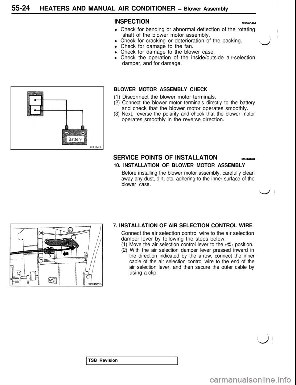
BLOWER MOTOR ASSEMBLY CHECK(1) Disconnect the blower motor terminals.
(2) Connect the blower motor terminals directly to the batteryand check that the blower motor operates smoothly.
(3) Next, reverse the polarity and check that the blower motoroperates smoothly in the reverse direction.
SERVICE POINTS OF INSTALLATIONM55KDAH
10. INSTALLATION OF BLOWER MOTOR ASSEMBLY
Before installing the blower motor assembly, carefully clean
away any dust, dirt, etc. adhering to the inner surface of the
blower case.7. INSTALLATION OF AIR SELECTION CONTROL WIRE
Connect the air selection control wire to the air selection
damper lever by following the steps below.
(1) Move the air selection control lever to the CQ position.
(2) With the air selection damper lever pressed inward in
the direction indicated by the arrow, connect the inner
cable of the air selection control wire to the end of the
air selection lever, and then secure the outer cable byusing a clip.
TSB Revision
Page 1107 of 1146
HEATERS AND MANUAL AIR CONDITIONER - Evaporator55-25
EVAPORATOR
M55RA- -
/REMOVAL AND INSTALLATION
9.0- 11 Nm
7.0 - 8.0 ftlbs.
i
O-ringRemoval steps
l *I, Connection of liquid pipe and suction hose
2. O-ring
3. Drain hose
4. Stopper
5. Glove box
6. Glove box outer case assembly
7. Under cover
8. Lower frame
9. A/C control unit
10. Evaporator
Pre-removal and Post-installation Operationl Discharge and Charging of Refrigerant
l Removal and lns~allation of Battery
SERVICE POINTS OF REMOVALM55RBAl
1.DISCONNECTION OF LIQUID PIPE AND SUCTION HOSEIf the hoses or pipes are disconnected, cap the hoses or
pipes with a blank plug to prevent entry of dust, dirt, and
water.
INSPECTIONM55RcADl Check for damage of the evaporator fin part.
l Check for damage or collapse of the drain hose.
l Check for peeling or cracking of the insulator.
FIN-THERM0 SENSOR AND AIR-INLET SENSOR CHECK
For information concerning the checking procedures, refer to
P.55-11.
iTSB Revision
Page 1108 of 1146
55-26HEATERS AND MANUAL AIR CONDITIONER - Evaporator
DISASSEMBLY AND REASSEMBLYM55RE- -Compressor oil: Freol S-83 or
Suniso 5GS
Disassembly steps
4*1. Clips
2. Evaporater case (upper)3.
Fin therm0 sensor4. AirInlet sensor
4*
5. Evaporator case (lower)
6.Evaporator assembly
7.Grommet8.Insulator9.Rubber insulator10.Clip11. Expansion valve
10/
9
/2OFOO40
1TSB Revision
SERVICE POINTS OF DISASSEMBLYM55RFAJ1. REMOVAL OF CLIPS
Remove the clips with a screwdriver covered with a shoptowel to prevent damage to case surfaces.
11. REMOVAL OF EXPANSION VALVE
Loosen the flare nut by using two wrenches (for both theinlet and outlet).