Page 1084 of 1146
55-2FULL AUTO AIR CONDITIONER........................40OTHER PARTS........................................................................62
AIR-CONDITIONER CONTROL PANEL*,POWER TRANSISTOR, BELT LOCK CONTROLLER........57
AIR-CONDITIONER CONTROL UNIT*................................56
REFRIGERANT LINE................................................................62
COMPRESSOR
........................................................................62SAFETY PRECAUTlONS........................................................56
CONDENSER AND CONDENSER FAN MOTOR
................
62SENSORS....................................................................................60
DAMPER CONTROL MOTOR ASSEMBLY*........................
58SERVICE ADJUSTMENT PROCEDURES............................56
ENGINE COOLANT TEMPERATURE SWITCH
....................62
TROUBLESHOOTING............................................................40
Page 1085 of 1146

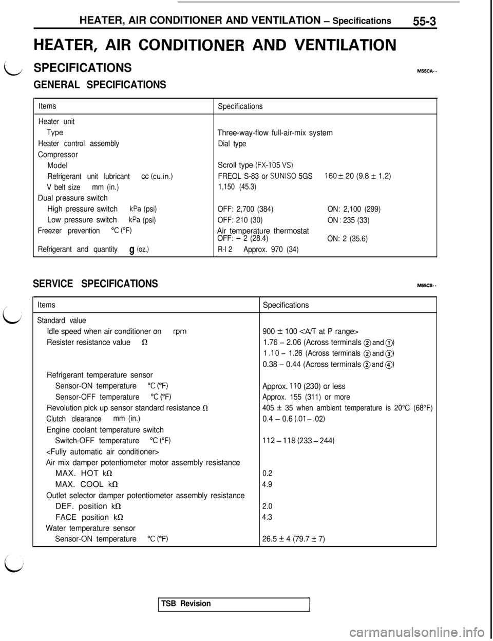
HEATER, AIR CONDITIONER AND VENTILATION - Specifications55-3
HEATER, AIR CONDITIONER AND VENTILATION
LSPECIFICATIONSM55CA. -
/’
L;
GENERAL SPECIFICATIONS
Items
Heater unit
Type
Heater control assembly
Compressor
Model
Refrigerant unit lubricant
cc (cu.in.1
V belt sizemm (in.)
Dual pressure switch
High pressure switch
kPa (psi)
Low pressure switchkPa (psi)
Freezer prevention
“C (“F)
Refrigerant and quantityg (oz.)
Specifications
Three-way-flow full-air-mix system
Dial type
Scroll type (FX-105 VS)
FREOL S-83 or SUNISO 5GS160 & 20 (9.8 + 1.2)
1,150 (45.3)
OFF: 2,700 (384)ON: 2,100 (299)
OFF: 210 (30)
ON
: 235 (33)
Air temperature thermostatOFF: - 2 (28.4)
ON: 2 (35.6)
R-l 2Approx. 970 (34)
SERVICE SPECIFICATIONSM55CB. -
Items
Standard value
Idle speed when air conditioner onrpm
Resister resistance value1R
Refrigerant temperature sensor
Sensor-ON temperature
“C (“F)
Sensor-OFF temperature“C (“F)
Revolution pick up sensor standard resistance 0
Clutch clearancemm (in.)
Engine coolant temperature switch
Switch-OFF temperature
“C (“F)
Air mix damper potentiometer motor assembly resistanceMAX. HOT
kQMAX. COOL
kS1
Outlet selector damper potentiometer assembly resistanceDEF. position
kS1FACE position
kfl
Water temperature sensor
Sensor-ON temperature
“C (“F)
Specifications
900
f 100 CA/T at P range>
1.76
- 2.06 (Across terminals @and 0)
1 .I 0 - 1.26 (Across terminals @and 0)
0.38 - 0.44 (Across terminals @and @)
Approx. 110 (230) or less
Approx. 155 (311) or more
405
f 35 when ambient temperature is 20°C (68°F)
0.4 - 0.6 (.Ol - .02)
112-118(233-244)
0.2
4.9
2.0
4.3
26.5 f 4 (79.7 + 7)
TSB Revision
Page 1086 of 1146
55-4 HEATER, AIR CONDITIONER AND VENTILATION -Specifications / Special Tools
LUBRICANTSM55CD. _
ItemsSpecified lubricants
Each connection of refrigerant lineFREOL S-83 or
SUNISO 5GS
Quantity
As required
SEALANT AND ADHESIVEM55CE- -
IItemsSpecified sealant and adhesiveI
Engine coolant temperature switch threaded part3M Nut Locking Part No. 4171 or equivalent
SPECIAL TOOLSMSSDA- -
multi-use tester)
TSB Revision
Page 1087 of 1146
HEATERS AND MANUAL AIR CONDITIONER - Troubleshooting55-5
HEATERS AND MANUAL AIR CONDITIONER
t+-/ TROUBLESHOOTING
L
M55ECAE
Symptom
Heater insufficientheatProbable cause
Obstructed heater outlets
Blend air dampers improperly adjusted or binding
Thermostat malfunction
Obstructed heater hoses
Remedy
Correct
Replace
No ventilation evenwhen mode selectionknob is operatedImproperly adjusted control cables
Plugged or partially plugged heater core
Incorrect adjustment of mode selection dampersIncorrect installation of mode selection controlwire
Ducts are incorrectly/incompletely connected,crushed, bent or clogged
Burnt-out fuse
Poor grounding
Malfunction blower switch
Malfunction resistorAdjust
Clean or replace
Adjust
Blower motor
inoperative
Repair or replace
ReplaceCorrect
Replace
Malfunction blower motor
Malfunction heater relay
Malfunction blower motor relay
TSB Revision
Page 1088 of 1146
55-6HEATERS AND MANUAL AIR CONDITIONER - Troubleshooting
CIRCUIT DAIGRAM
P\IR CONDITIONER CONTROL UNIT CIRCUIT
1 Batte
( Alternator k
2-Jl-
-use
Fuse
-yq
L-l
Fuse
vi ~~o~~;motor ;?IResistor;
r---HI---MH:---ML---I n
IIHeater control panelI-
fI.IAir conditioner switch
1
Air conditioner control unit
A/CI
Regulator
IT
If
I
1II
1 IFin therm0 sensorAir inlet sensor
I” ”I\
Revolution pick up sensori
Compressor
@IDY
vi;
TSB Revision
2OFOO43
I
Page 1089 of 1146

L
2OFOO85HEATERS AND MANUAL AIR CONDITIONER
- Trqubleshooting55-7
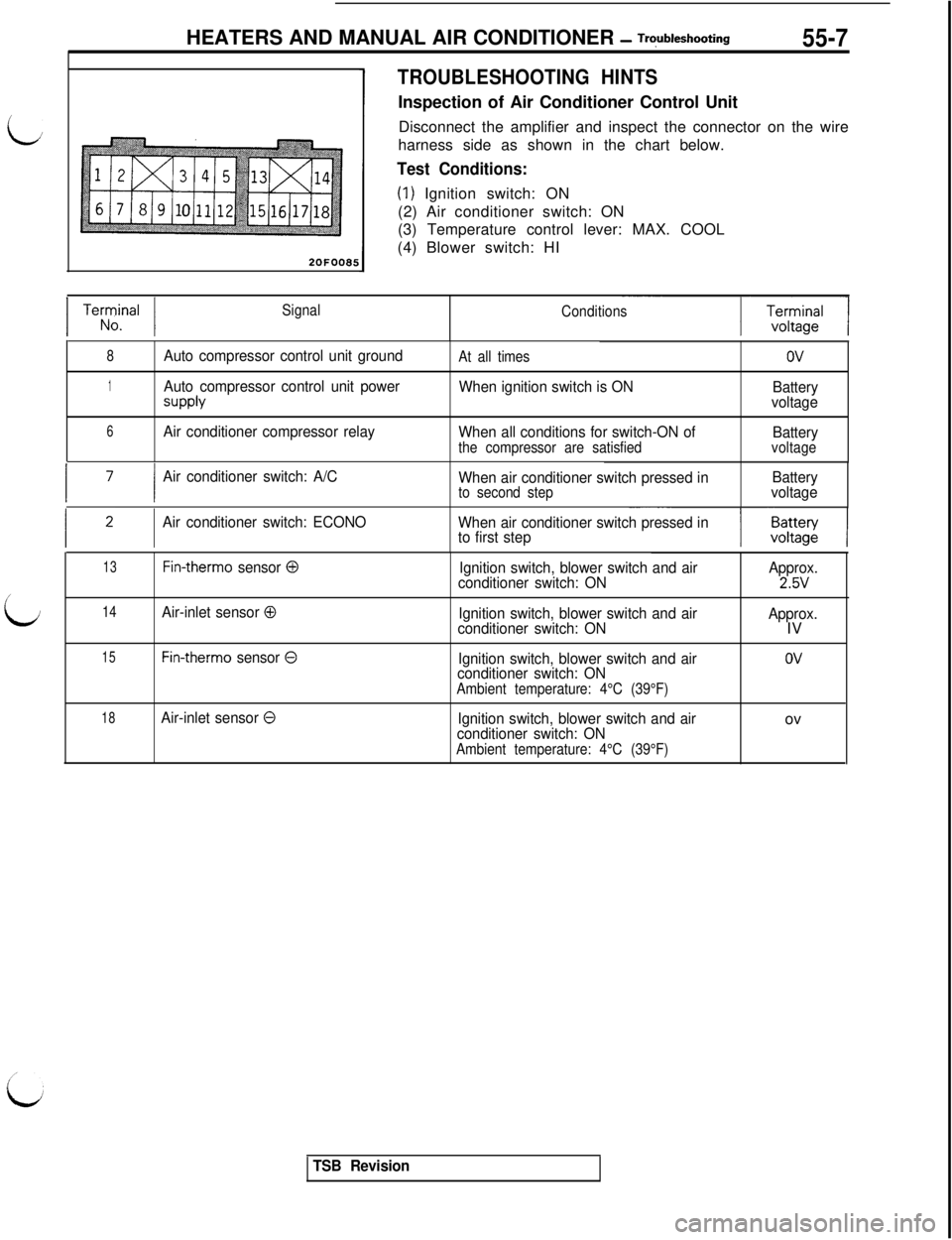
TROUBLESHOOTING HINTSInspection of Air Conditioner Control Unit
Disconnect the amplifier and inspect the connector on the wire
harness side as shown in the chart below.
Test Conditions:
(1) Ignition switch: ON
(2) Air conditioner switch: ON
(3) Temperature control lever: MAX. COOL
(4) Blower switch: HI
1 Terrrnal 1Signal
Conditions
8Auto compressor control unit groundAt all timesov
1Auto compressor control unit power
SUPPlY
When ignition switch is ON
Battery
voltage
6Air conditioner compressor relay
When all conditions for switch-ON of
Battery
the compressor are satisfiedvoltage
I ’I
Air conditioner switch: A/C
When air conditioner switch pressed inBattery
to second stepvoltage
Air conditioner switch: ECONO
When air conditioner switch pressed in
to first step
13Fin-therm0 sensor 0Ignition switch, blower switch and airApprox.
conditioner switch: ON2.5V/
LJ14Air-inlet sensor 0Ignition switch, blower switch and air
conditioner switch: ONApprox.IV
15Fin-therm0 sensor 0Ignition switch, blower switch and air
conditioner switch: ON
Ambient temperature: 4°C (39°F)
OV
18Air-inlet sensor 0Ignition switch, blower switch and air
conditioner switch: ON
Ambient temperature: 4°C (39°F)ov
TSB Revision
Page 1090 of 1146

55-8HEATERS AND MANUAL AIR CONDITIONER - Troubleshooting
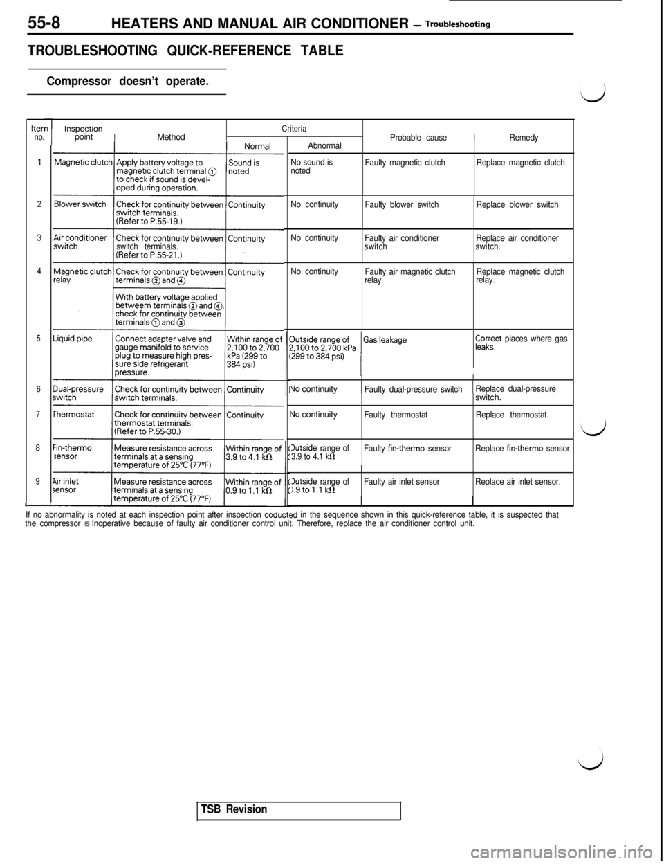
TROUBLESHOOTING QUICK-REFERENCE TABLE
Compressor doesn’t operate.
hen
no.
4
5
6
7
8
9
-
I
I
/
L
switch terminals.
Sensor
”
1
InspectronCriteriapointIMethodProbable causeIRemedy
Abnormal
No sound is
notedFaulty magnetic clutchReplace magnetic clutch.
No continuity
Faulty blower switchReplace blower switch
No continuity
Faulty air conditioner
switchReplace air conditioner
switch.
No continuity
Faulty air magnetic clutch
relayReplace magnetic clutch
relay.
pa;?’ places where gas
II
Vo continuityFaulty dual-pressure switchReplace dual-pressure
\Jo continuityIFaulty thermostatswitch.Replace thermostat.
Outside range of3.9 to 4.1 kfiFaulty fin-therm0 sensorReplace fin-therm0 sensor
3utside range ofFaulty air inlet sensor1.9tol.l kQReplace air inlet sensor.
If no abnormality
is noted at each inspection point after inspection coducted in the sequence shown in this quick-reference table, it is suspected that
the compressor IS Inoperative because of faulty air conditioner control unit. Therefore, replace the air conditioner control unit.
d
d
TSB Revision
Page 1091 of 1146

HEATERS AND MANUAL AIR CONDITIONER - safety Pre=utm55-9
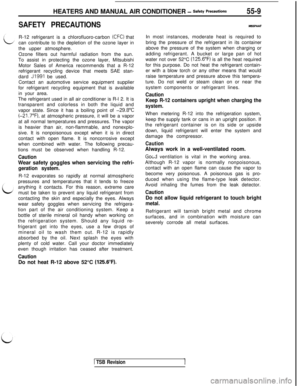
SAFETY PRECAUTIONSR-12 refrigerant is a chlorofluoro-carbon
(CFC) that
can contribute to the depletion of the ozone layer in
the upper atmosphere.
Ozone filters out harmful radiation from the sun.
To assist in protecting the ozone layer, Mitsubishi
Motor Sales of America recommends that a R-12
refrigerant recycling device that meets SAE stan-
dard
J1991 be used.
Contact an automotive service equipment supplier
for refrigerant recycling equipment that is available
in your area.
The refrigerant used in all air conditioner is R-l 2. It is
transparent and colorless in both the liquid and
vapor state. Since it has a boiling point of
-29.8”C(-21.7”F), at atmospheric pressure, it will be a vapor
at all normal temperatures and pressures. The vapor
is heavier than air, non-flammable, and nonexplo-
sive. It is nonpoisonous except when it is in direct
contact with open flame. It is noncorrosive except
when combined with water. The following precau-
tions must be observed when handling R-12.
CautionWear safety goggles when servicing the refri-
geration system.R-12 evaporates so rapidly at normal atmospheric
pressures and temperatures that it tends to freeze
anything it contacts. For this reason, extreme care
must be taken to prevent any liquid refrigerant from
contacting the skin and especially the eyes. Always
wear safety goggles when servicing the refrigera-
tion part of the air conditioning system. Keep a
bottle of sterile mineral oil handy when working on
the refrigeration system. Should any liquid re-
frigerant get into the eyes, use a few drops of
mineral oil to wash them out. R-12 is rapidly
absorbed by the oil. Next splash the eyes with
plenty of cold water. Call your doctor immediately
even though irritation has ceased after treatment.
CautionDo not heat R-12 above 52°C
(125.6”F).
M55PAAFIn most instances, moderate heat is required to
bring the pressure of the refrigerant in its container
above the pressure of the system when charging or
adding refrigerant. A bucket or large pan of hot
water not over 52°C
(125.6”F) is all the heat required
for this purpose. Do not heat the refrigerant contain-
er with a blow torch or any other means that would
raise temperature and pressure above this tempera-
ture. Do not weld or steam clean on or near the
system components or refrigerant lines.
Caution
Keep R-12 containers upright when charging the
system.When metering R-12 into the refrigeration system,
keep the supply tank or cans in an upright position. If
the refrigerant container is on its side or upside
down, liquid refrigerant will enter the system and
damage the compressor.
CautionAlways work in a well-ventilated room.
Good ventilation is vital in the working area.
Although R-12 vapor is normally nonpoisonous,
contact with an open flame can cause the vapor to
become very poisonous. A poisonous gas is pro-
duced when using the flame-type leak detector.
Avoid inhaling the fumes from the leak detector.
CautionDo not allow liquid refrigerant to touch bright
metal.Refrigerant will tarnish bright metal and chrome
surfaces, and in combination with moisture can
severely corrode all metal surfaces.
1 TSB Revision