1991 MITSUBISHI 3000GT air condition
[x] Cancel search: air conditionPage 948 of 1146

51-10EXTERIOR - Service Adjustment Procedures
68FOO51
Multl-use tester
,SERVICE ADJUSTMENT PROCEDURES
INSPECTION OF ACTIVE AERO SYSTEM
1. INSPECTION BY WARNING LIGHT
d!Turn the ignition switch from “OFF” to “ON” to see if the
warning light is lit for approx. three seconds and then goes
out. If not, replace the control unit.
NOTE
(1) The active aero control unit has a self-check function
which is designed as follows: Turn the ignition switch
from “OFF” to “ON”. If the unit is in normal condition,
the warning light is lit for approx. three seconds and
then goes out.
(2) If the front venturi skirt does not return to the standard
condition properly in normal use, the warning light
comes on
2. INSPECTION BY ACTIVE AERO SWITCH AT AUTO 2
(1) With the vehicle stopped, insert the key in the ignition
key cylinder.
(2) Set the active aero switch to AUTO 2 to make sure that
the active aero system is placed in the operative
condition and the indicator light comes on. Then turn off
the active aero switch to confirm that the system
LCJreturns to the standard condition and the indicator light
goes out.
(3) If there is abnormality, check the following parts.
l Active aero switch
l Lighting monitor switch
l Air dam link assembly and rear spoiler
l Wiring harness
3. INSPECTION WITH MULTI-USE TESTER
Using pseudo vehicle speed input function of the multi-use
tester, inspection can be made by means of vehicle speed.
(1) Set the multi-use tester to the diagnosis connector.
(2) Turn the ignition switch to “ACC” or “ON”.
(3) Place the active aero switch to AUTO 1.
(4) Using the multi-use tester, increase the vehicle speed
to approx. 80 km/h (50 mph) or more to make sure that
the active aero system is placed to the operative
condition. Then decrease the vehicle speed to approx.
50 km/h (30 mph) or less to confirm that the system
returns to the standard condition.
1 TSB Revision
Page 950 of 1146

51-12EXTERIOR - Front BummerIREMOVAL
,AND INSTALLATION
9
F IL
d.94Lag
.d,
;3
\Removal steps
1. Front under cover side panel
2. Front under cover center panel
3. Side cover panel
4. Front cover panel
5. Center cover panel
I)*6. Front under cover panel
7. Front splash shield extension
8. Fog light
9. License plate bracket
7i(Vehicles without
active aero system)
(Vehicles with
active aero system)
10. Front combination light
11. Optical horn lens
12. Clips with screw
13. Tapping screws
14. Bolts;
51: Bu;per face assembly
17. Bumper reinforcement assembly
SERVICE POINT OF INSTALLATION
6. INSTALLATION OF FRONT UNDER COVER PANEL
Install the air dam link assembly in the operative condition
for ease of front under cover panel.
ITSB Revision
Page 961 of 1146

EXTERIOR - Aero Parts
18FO257
RearFrontView
A_ View B
Adhesive
18FO17533. INSPECTION OF ACTIVE AERO SWITCH
Operate the switch to check the continuity between the
terminals.
(Automatic
reset type)
NOTEO-0 indicates that there is continuity between the terminals.
SERVICE POINTS OF INSTALLATION
11. INSTALLATION OF AIR DAM LINK ASSEMBLY
Install the air dam link assembly in the operative condition
for ease of front under cover panel.
1. INSTALLATION OF SIDE AIR DAM
Install the side air dam by the same procedure as the side
garnish (refer to
P.51-181, provided that specified adhesive
is used.
Specified adhesive: 3M ATD Part No. 8609 SUPER FAST
URETHAN or equivalent
I---TSB Revision
Page 995 of 1146

L
LINTERIOR
- Headlining52A-17
HEADLININGM52lJDBC[EMOVAL AND INSTALLATION
Pre-removal and Post-installation Operationl Removal and Installation of Rear
Roof Rail Trim (Refer to P52A-13.)l Removal and lnstallatron of FrontPillarTrim (Refer to P.52A-13.)Removal steps
1. Hanger bracket
2. Sash guide cover mounting bolt
3. Clip
4. Passenger compartment temperature
sensor (Vehicles with full automatic
air conditioner)
5. Sunvisor assembly
6. Sunvisor holder
7. Room light assembly
8. HeadliningTSB Revision
Page 1012 of 1146

52B-2SUPPLEMENTAL RESTRAINT SYSTEM (SRS) - General informationGENERAL INFORMATION
INTRODUCTIONThe Supplemental Restraint System (SRS) is de-
signed to supplement the driver’s seat belt to help
reduce the risk or severity of injury to the driver by
activating and deploying a driver’s-side air bag in
certain frontal collisions.
The SRS consists of: left front and right front impact
sensors located, one each, on the right and left front
upper frame lowers; an air bag module located in
the center of the steering wheel, which contains the
folded air bag and an inflator unit; the SRS diagnosis
unit located under the rear console assembly, which
monitors the system, and which contains a safing
impact sensor; an SRS warning light located on the
instrument panel, which indicates the operational
status of the SRS; a clock spring interconnection
located within the steering column; system wiring
and wiring connectors; and a knee bolster located
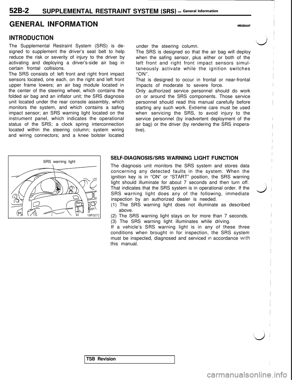
SRS warning light
M52BAAFunder the steering column.
The SRS is designed so that the air bag will deploy
when the safing sensor, plus either or both of the
left front and right front impact sensors simul-
taneously activate while the ignition switches
“ON”.
That is designed to occur in frontal or near-frontal
impacts of moderate to severe force.
Only authorized service personnel should do work
on or around the SRS components. Those service
personnel should read this manual carefully before
starting any such work. Extreme care must be used
whenservicing the SRS, to avoid injury to the
service personnel (by inadvertent deployment of the
air bag) or the driver (by rendering the SRS inopera-
tive).
SELF-DIAGNOSIS/SRS WARNING LIGHT FUNCTION
The diagnosis unit monitors the SRS system and stores data
concerning any detected faults in the system. When the
ignition key is in “ON” or “START” position, the SRS warning
light should illuminate for about 7 seconds and then turn off.
That indicates that the SRS system is in operational order. If the
SRS warning light does any of the following, immediate
inspection by an authorized dealer is needed.
(1) The SRS warning light does not illuminate as described
above.
(2) The SRS warning light stays on for more than 7 seconds.
(3) The SRS warning light illuminates while driving.
If a vehicle’s SRS warning light is in any of these three
conditions when brought in for inspection, the SRS system
must be inspected, diagnosed and serviced
In accordance wrth
this manual.
TSB Revision
Page 1036 of 1146

52B-26 SUPPLEMENTAL RESTRAINT SYSTEM (SRS) - Troubleshooting
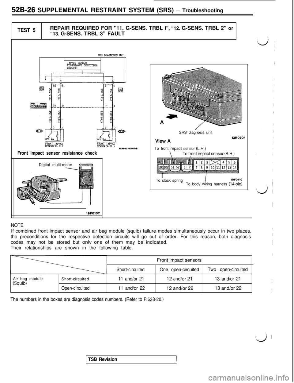
TEST 5REPAIR REQUIRED FOR "11. G-SENS. TRBL I”, “12. G-SENS. TRBL 2” or
“13. G-SENS. TRBL 3” FAULT
SRS DIAGNOSIS UN1
IMPACT S!NSOR~M&N"E DETECTION
FRONT IMPACTSENS0RtL.H.)FRONT IMPACTsEN80R(R. H. )--u-~,w-*
Front impact sensor resistance checkDigital multi-meter
r ~1iii”~“‘.,,,,/ ?\I. I,// q
NOTEIf combined front impact sensor and air bag module (squib) failure modes simultaneously occur in two places,
the preconditions for the respective detection circuits will go out of order. For this reason, both diagnosis
codes may not be stored but only one of them may be indicated.
Their relationships are shown in the following table.
Front impact sensors
Air bag module
(Squib)Short-circuitedOpen-circuitedShort-circuited
11 and/or 21
11 and/or 22One open-circuitedTwo open-circuited12 and/or 2113 and/or 21I12 and/or 2213 and/or 22
I
The numbers in the boxes are diagnosis codes numbers. (Refer to P.52B-20.)
/SRS diagnosis unit
View A
13u070rTo frontimDact sensor
(L.H.)
ITo clock springI19FOllO
To body wiring harness (14-pin)
lQFO102
1 TSB Revision
Page 1043 of 1146

SUPPLEMENTAL RESTRAINT SYSTEM (SRS) - Troubleshooting 52B-33
1 TEST 6 )REPAIR REQUIRED FOR “21. SQUIB TRBL 1” or “22. SQUIB TRBL 2” FAULT1
i
FRONTSIDE
Ez
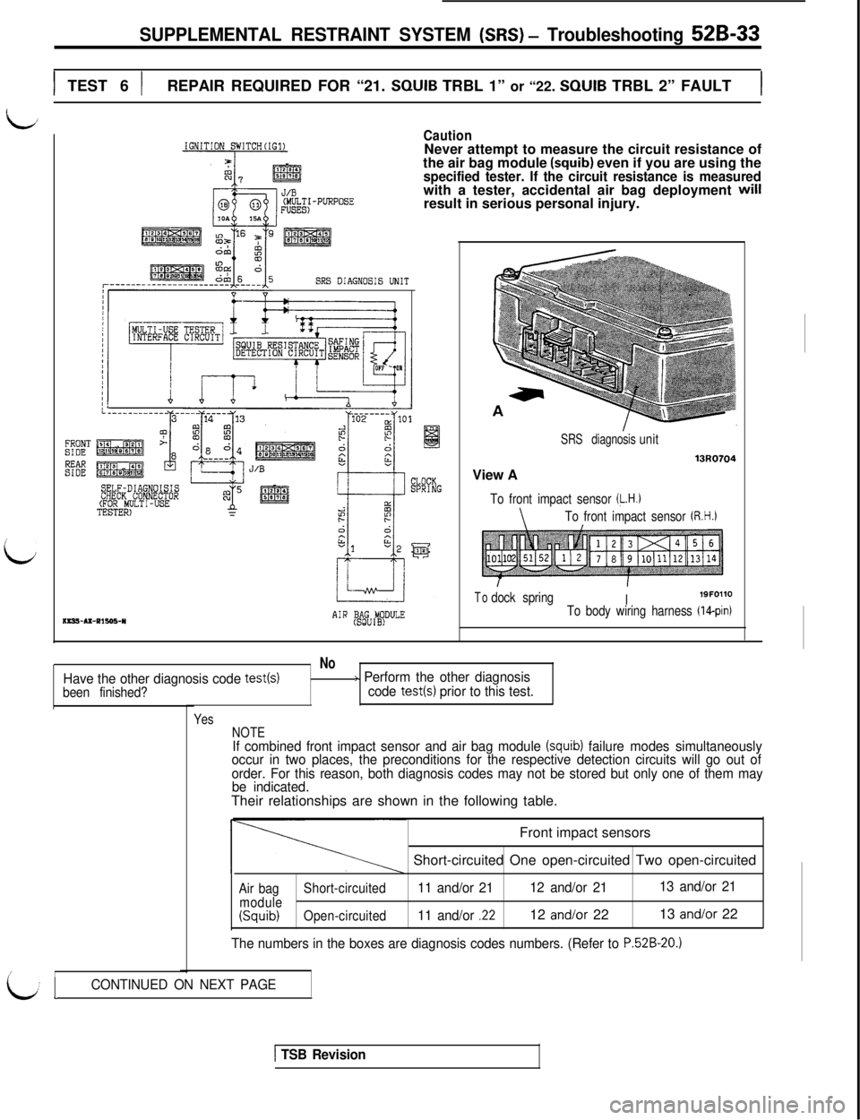
IGNITION SWITCH(IG1)CautionNever attempt to measure the circuit resistance of
the air bag module
(squib) even if you are using thespecified tester. If the circuit resistance is measuredwith a tester, accidental air bag deployment will
result in serious personal injury.
SRS DIAGNOSIS UNIT
------I
SELF-DIAGNOISISCHECK CONNECTOR(FOR MULTI-USETESTER)ms!+Ax-Pls95-Y
J/B
AIR (BSAgGU#DULEView A
SRS diagnosisunit
13uo704
To front impact sensor (L.H.1
\To front impact sensor (R.H.)
Todock springI19FOllOTo body wiring harness (IQpin)
No
Have the other diagnosis code test(s)/> Perform the other diagnosis
been finished?code test(s) prior to this test.
/I
Yes
NOTE
If combined front impact sensor and air bag module (squib) failure modes simultaneously
occur in two places, the preconditions for the respective detection circuits will go out of
order. For this reason, both diagnosis codes may not be stored but only one of them may
be indicated.Their relationships are shown in the following table.
Front impact sensors
Short-circuited One open-circuited Two open-circuited
Air bagShort-circuited11 and/or 2112 and/or 2113 and/or 21
module(Squib)Open-circuited11 and/or .2212 and/or 2213 and/or 22
The numbers in the boxes are diagnosis codes numbers. (Refer to P.52B-20.)
LICONTINUED ON NEXT PAGE
1 TSB Revision
Page 1083 of 1146

55-1
HEATER, AIR
CONDITIONER
AND VENTILATION
CONTENTSM55AA- -
HEATERS AND AIR CONDITIONING................3HEATER UNIT*........................................................................22
SPECIFICATIONS
....................................................................3REFRIGERANT LINE................................................................35General Specifications
........................................................3RESISTOR................................................................................20Lubricants
............................................................................4SAFETY PRECAUTIONS........................................................9Sealant and Adhesive............................................................4
Service Specifications3SERVICE ADJUSTMENT PROCEDURES............................10........................................................
SPECIAL TOOLS4Charging Procedures............................................................11
i
........................................................................Charging the Refrigerant....................................................12Compressor Drive Belt Adjustment....................................11
HEATERS AND MANUAL AIR CONDITIONER5Compressor Noise................................................................16
................................................16
AIR CONDITIONER SWITCH................................................21Handling Tubing andFittings
Idle-up Operation Check....................................................17
BELT LOCK CONTROLLER20Performance Test................................................................15....................................................
BLOWER ASSEMBLYPower Relay Check............................................................17............................................................23Refrigerant Leak Repair Procedure....................................15COMPRESSOR........................................................................
27TestProcedures....................................................................10
CONDENSER AND CONDENSER FAN MOTOR................33TROUBLESHOOTING............................................................5
ENGINE COOLANT TEMPERATURE SWITCH....................
39VENTILATORS (AIR INLET AND AIR OUTLET)................38
EVAPORATOR
........................................................................
25VENTILATORS (INSTRUMENT PANEL)*............................36
HEATER CONTROL ASSEMBLY*
........................................18CONTINUED ON NEXT PAGE
SUPPLEMENTAL RESTRAINT SYSTEM (SRS)
(1)A Supplemental Restraint System (SRS), which uses a driver-side air bag, has been installed in the 3000GT.(2)The SRS includes the following components: impact sensors, SRS diagnosis unit: SRS warning light, air bagmodule, clock spring, interconnecting wiring. Other SRS-related components (that may have to be
removed/installed in connection with SRS service or maintenance) are indicated in the table of contents byan asterisk (*).
WARNING!(1)Improper service or maintenance of any component of the SRS, or any SRS-related component, can lead to
personal injury or death to service personnel (from inadvertent firing of the air bag) or to the driver (fromrendering the
SRS inoperative).(2) Service or maintenance of any SRS component or SRS-related component must be performed only at anauthorized MITSUBISHI dealer.
(3) MITSUBISHI dealer personnel must thoroughly review this manual, and especially its GROUP 52B
-Supplemental Restraint System (SRS), before beginning any service or maintenance of any component of theSRS or any SRS-related component.