Page 1117 of 1146
HEATERS AND MANUAL AIR CONDITIONER - Rdrigerant Line55-35
REFRIGERANT LINE
/’REMOVAL AND INSTALLATION
L;Pre-removal and Post-installation Operation
l Discharge and Charging of Refrigerant(Refer to P.55-14, 11.)
Removal steps
a*1. High-pressure hosel *2. High-pressure pipe
3. Liquid pipe A
4. Liquid pipe B
5. Low-pressure hose B
6. Low-pressure hose A
7. Receiver bracket
8. Receiver
9. Dual-pressure switch23 Nm
17 ft.lbs.-\-M55UA-
-
1: Piping connection
O-ring20N0089
1
O-ringCompressor oil: Freol S-83 or Suniso 5GS
13 Nm
9.0
ft.lbs.
9.0-11 Nm7.0 -8.0 ft.lbs.
\
TE NUTII” 1.1119.0 ft.lbs.
7.0 - 8.0 ft.lbs.
/
‘Ill
q9
8
2OFOO68
SERVICE POINTS OF REMOVALMIBUBAC
1. REMOVAL OF HIGH-PRESSURE HOSE
/ 2. HIGH-
PRESSURE PIPELoosen the flare nut ,by using two wrenches.
INSPECTIONMHUCAD
CHECKING DUAL PRESSURE SWITCHFor information concerning the checking procedures of the dual
pressure switch, refer to “Service Adjustment Procedures” on
P.55-10.
1 TSB Revision
Page 1118 of 1146
55-36 HEATERS AND MANUAL AIR CONDITIONER -Ventilators (Instrument Panel)
VENTILATORS (INSTRUMENT PANEL)M55YA- -
REMOVAL AND INSTALLATION
-16
/‘4
Removal steps
l * +a1. Knee protector
(Refer to GROUP 52A-Instrument Panel.)
2. Foot shower duct
3. Lap cooler duct
4. Under cover
5. Belt lock controller
6. Side defroster hoses A
7. Duct (Vehicles without air conditioner)
** l +8. instrument panel (Refer to GROUP 52A-instrument Panel.)
9. Center duct
10. Air duct (right side)
11. Air duct (left side)12. Distribution duct (center)
13.Defroster duct14. Side defroster hoses B
15. Defroster garnishes
16.Photo sensor17. Center air outlet assembly
18. Side air outlet assembly
19. Distribution duct (foot)2OFOO55
Ij
I
I
I
.I
I
I
!
I
‘d
TSB RevisionI
Page 1119 of 1146
HEATERS AND MANUAL AIR CONDITIONER -Ventilators (Instrument Panel) 55-37
/ 2OFOO321
SERVICE POINTS OF REMOVALM55YBAH
15. REMOVAL OF DEFROSTER GARNISHES
Using the trim stick, remove the defroster garnishes fromthe instrument panel.
16. REMOVAL OF PHOTO SENSORUsing the trim stick, remove the photo sensor from the
defroster garnish.
17. REMOVAL OF CENTER AIR OUTLET ASSEMBLY
Disengaging the clips (2 positions) of the center air-outlet
assembly with a flat tip screwdriver, remove the center airoutlet assembly with the trim stick.
1 TSB Revision
Page 1120 of 1146
55-38Ventilators (Air Inlet
HEATERS AND MANUAL AIR CONDITIONER - and Air Outlet)
VENTILATORS (AIR INLET AND AIR OUTLET)M55YD. -
REMOVAL AND INSTALLATIONinlet garnishes removal steps
1. Windshield wiper arm
2. Front deck garnish
3. Inlet garnish (right)
4. Inlet garnish (left)Rear ventilation duct removal steps
5. Rear ventilation duct A** l6. Side air dam (side sill)
(Refer to GROUP 51 - Aero Parts.)7. Rear ventilation duct B
:LI’
I
I
I
I
‘d ’
I
I
I
1 TSB RevisionI
Page 1121 of 1146
Pre-removal and Post-installation Operationl Draining and Refilling of Engine Coolant(Refer to GROUP 00 - Maintenance Service.)
1. Engine coolant temperature switchHEATERS AND MANUAL AIR CONDITIONER
- Z!&E%Ltch55-39
ENGINE COOLANT TEMPERATURE SWITCH
M55xA- -
L
REMOVAL AND INSTALLATIONSealant: 3M Nut Locking Part No.
4171 or equivalent
BQQQQQ20A0199INSPECTION
MSSXCAAENGINE COOLANT TEMPERATURE SWITCH
(ALWAYS-
CLOSED TYPE CHECK)
(1) Immerse the engine coolant temperature switch in oil and
heat by a gas stove or similar method so as to increase the
oil temperature.(2) Check to be sure that the engine coolant temperature
switch is switched OFF when the oil temperature reaches
the standard value.Standard value: 112
- 118°C (233 - 244°F)
CautionUse engine oil for this test; stir it well while heating,
and do not heat more than necessary.
1 TSB Revision
Page 1122 of 1146

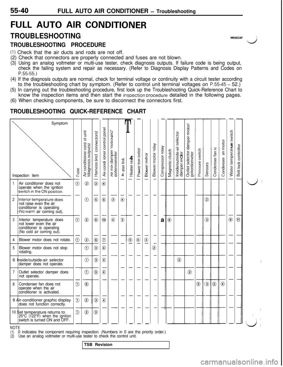
55-40FULL AUTO AIR CONDITIONER - Troubleshooting
FULL AUTO AIR CONDITIONER
TROUBLESHOOTINGM55ECAF
TROUBLESHOOTING PROCEDUREd
(1) Check that the air ducts and rods are not off.
(2) Check that connectors are properly connected and fuses are not blown.
(3) Using an analog voltmeter or multi-use tester, check diagnosis outputs. If failure code is being output,
check the failing system and repair as necessary. (Refer to Diagnosis Display Patterns and Codes on
P.55-55.)
(4) If the diagnosis outputs are normal, check for terminal voltage or continuity with a circuit tester accordingto the troubleshooting chart by symptom. (Refer to control unit terminal voltages on
P.55-45 - 52.)
(5) In carrying out the troubleshooting procedure, first look up the Troubleshooting Quick-Reference Chart toknow the inspection items and then start the
insoection orocedure detailed in the following pages.
(6) When checking components, be sure to disconnect the connectors first.
TROUBLESHOOTING QUICK-REFERENCE CHART
-
%I.?
0
-
(i;
0-
-
-
z
s
5
-
z3Ec-l-cm85LQgc .”0”SO0s“E$3
0
0
0
0.
0
0
0
-
-zbij2s”
-?‘-
aF&I
0
0
0
0
0
0
G
-
s
5
-
-
55n
>F8b5.-
F
8.$
0
:
G
0
G
is
z
-
G-
-
-
-
T4
L??ctE;
2-
-
-
G-
-
-
-
-
-
-.
-
b725
6
f53a0-
-
-
G-
-
-
-
-
-
-
86
E&3-0a-
-
-
-
3-
-
-
-
-
-
-
-
i?i?!
biiz?
E
0”-
-a
-
-
-
-
-
-
-
GE
21z6:1D-
-
-
-
-
0
-
-
-
-
-
;(if
zzit
5
5‘dTC
T-
-:
2
2
::ii3z;
2%;sjE1.0
;g5E
-
:
,,
,
1
-
-
-
-
0
-
-
-
-
-
k=eE00
t:0+i
-
-
a
-
-
-
-
-
-
-
-
b5E
5
&is*
s0-
-
-
-
-
-
-
G
-
-
-
-
5.T
Bz??3;i;b
Ecz
5-
-
0
-
-
-
-
-
-
-
-
1
225cn-
s
s----
s---
Symptom
Inspection item
7i;if
II:.?t.!
1E5z
iT-a,?z
5g< 13;$
zg
z
G-
-
-
-
-
-
-
.k?alL-0s
‘v, 0SE95anUE
ma‘0Y
s‘-5764
-
-
%G
-
-
-
-
-
-
-
Air conditioner does not
operate when the ignition
not raise even the air
conditioner is operating
(No’warm air coming out).
LJ
I
I~
‘L/,
3Interior temperature does
not lower even the air
conditioner is operating
(No cold air coming out).
4
Blower motor does not rotate.
5Blower motor does not stop
rotating.
06 Inside/outside-air selectordamper does not operate.
7Outlet selector damper does
not operate.
8Condenser fan does not
operate when the air
conditioner is activated.9 Air-conditioner graphic display
does not function correctly.
IO Set temperature returns to25°C (122°F) when the ignitionswitch is turned ON and OFF.
NOTE(1)
(2)0 indicates the component requiring inspection. (Numbers in 0 are the priority order.)
Use an analog voltmeter or multi-use tester to check the control unit.TSB Revision
Page 1123 of 1146

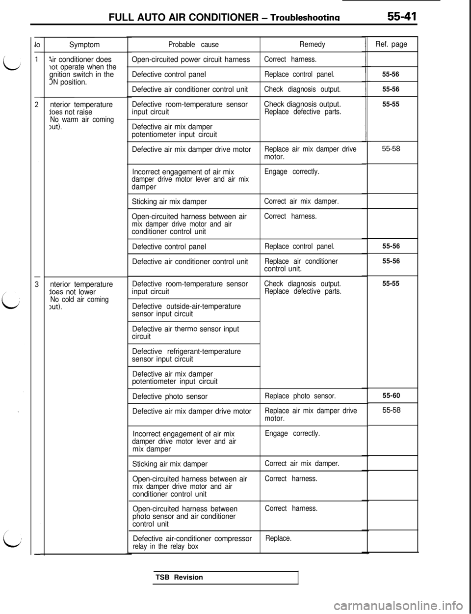
FULL AUTO AIR CONDITIONER - Troubleshootina55-41
Symptom
4ir conditioner doeslot operate when the
gnition switch in the
3N position.
nterior temperature
lees not raiseNo warm air coming1ut).
nterior temperatureAoes not lowerNo cold air coming,ut).Probable cause
Open-circuited power circuit harness
Defective control panel
Defective air conditioner control unit
Defective room-temperature sensor
input circuit
Defective air mix damper
potentiometer input circuit
Remedy
Correct harness.
Replace control panel.
Check diagnosis output.
Check diagnosis output.Replace defective parts.
Defective air mix damper drive motorReplace air mix damper drivemotor.
Incorrect engagement of air mix
damper drive motor lever and air mix
damperEngage correctly.
Sticking air mix damper
Open-circuited harness between air
mix damper drive motor and airconditioner control unit
Defective control panel
Defective air conditioner control unit
Correct air mix damper.
Correct harness.
Replace control panel.
Replace air conditioner
control unit.
Defective room-temperature sensor
input circuit
Defective outside-air-temperature
sensor input circuit
Check diagnosis output.
Replace defective parts.
Defective air therm0 sensor input
circuit
Defective refrigerant-temperature
sensor input circuit
Defective air mix damper
potentiometer input circuit
Defective photo sensor
Replace photo sensor.
Defective air mix damper drive motorReplace air mix damper drive
motor.
Incorrect engagement of air mixdamper drive motor lever and airmix damper
Engage correctly.
Sticking air mix damper
Open-circuited harness between air
mix damper drive motor and airconditioner control unit
Open-circuited harness between
photo sensor and air conditioner
control unit
Correct air mix damper.
Correct harness.
Correct harness.
Defective air-conditioner compressorReplace.
relay in the relay boxTSB Revision
Ref. page
55-56
55-56
55-55
55-58
55-56
55-56
55-55
55-60
55-58
Page 1124 of 1146
55-42FULL AUTO AIR CONDITIONER - Troubleshooting
Open-circuitedharness between
ower transistor and air conditionerCorrect harness.
ective air conditioner control
Defective air conditioner controlTSB Revision
d,
I
I
I
I
LA1
I
I
I
Id