Page 4 of 1146

SUPPLEMENTAL RESTRAINT SYSTEM (SRS)
dir J
bag module, clock spring, interconnecting wiring. Other SRS-related comp\
onents (that may have to be
(*).
The Supplemental Restraint System (SRSI-related components are shown in the following MASTER TABLE
OF CONTENTS. Be sure to carefully read and understand the WARNING below \
before proceeding.
Group number
22.23
32
36
42
52A
Group nameSRS-related components
FUELCRUISE CONTROL SYSTEM/ P.13-185
MANUALTRANSAXLE.TRANSAXLE CONTROLAUTOMATIC TRANSAXLE
POWER PLANT MOUNTRIGHT MEMBER, LEFT MEMBER AND CROSSMEMBERP.32-6
ELECTRONIC CONTROLSUSPENSION’STEERING ANGULAR VELOCITY SENSORP.33B-19
PARKING BRAKESPARKING BRAKE LEVER AND PARKiNG BRAKE CABLE/ P.36~5I
STEERING/POWER STEERING GEAR BOX/ P.37A-17
/STEERING WHEEL AND SHAFTj P.37A-13
BODY
INTERIOR
FENDER
FLOOR CONSOLE/ P.52A-11
FRONT SEAT
INSTRUMENT PANEL
P52A-18
P.52A-8
CHASSIS ELECTRICAL
SEAT BELT
COLUMN SWITCH
HORN SWITCH
IGNITION SWITCH
P.52A-25
P.54-73
P.54-78
1 P.54-6
RADIO REMOTE-CONTROL/ P.54.110
HEATER, AIR CONDITIONERAIR-CONDITIONER CONTROL PANELAND VENTILATIONAIR-CONDITIONER CONTROL UNITP.55-56
/DAMPER CONTROL MOTOR ASSEMBLYI
/HEATER CONTROL ASSEMBLY1 P.55-18I
HEATER UNIT.1 P.55-22
WARNING!
VENTILATORS (INSTRUMENT PANEL)P.55-36
(1) Improper service or maintenance of any component of the SRS, or an\
y SRSrelated component,
can lead to personal injury or death to service personnel (from inadver\
tent firing of the air bag) or
to the driver (from rendering the SRS inoperative).
(260°F) in baking or in
drying after painting, remove the SRS components (air bag module, SRS d\
iagnosis unit, front
perfarmed
only at an authorized MITSUBISHI dealer.
52B
- Supplemental Restraint System (SRS), before beginning any service or m\
aintenance of any
component of the SRS or any SRS-related component.
1 TSB RevisionI
Page 950 of 1146
51-12EXTERIOR - Front BummerIREMOVAL
,AND INSTALLATION
9
active aero system>
F IL
d.94Lag
.d,
;3
\Removal steps
1. Front under cover side panel
2. Front under cover center panel
3. Side cover panel
4. Front cover panel
5. Center cover panel
I)*6. Front under cover panel
7. Front splash shield extension
8. Fog light
9. License plate bracket
active aero system>
7i(Vehicles without
active aero system)
(Vehicles with
active aero system)
10. Front combination light
11. Optical horn lens
12. Clips with screw
13. Tapping screws
14. Bolts;
51: Bu;per face assembly
17. Bumper reinforcement assembly
SERVICE POINT OF INSTALLATION
6. INSTALLATION OF FRONT UNDER COVER PANEL
Install the air dam link assembly in the operative condition
for ease of front under cover panel.
ITSB Revision
Page 990 of 1146
52A-12INTERIOR - Trims
19POO70
4Trim
19POO80
hornm
in.)
19POO8,
Pin
Trim
19POO8219POO80TRIMS
IM52UCW
TRIM CLIP REMOVAL/INSTALLATION
PROCE-DURES
The type of clip shown in the illustration, which is used for the
Eli ~
installation of instrument panel, should be removed and
installed by the following procedures described below.
REMOVAL
(1) Use a cross-tip (+) screwdriver to push inward the pin (at
the center of the trim clip) to a depth of about 2 mm
(.08
in.).(2) Pull the trim clip outward to remove it.
Caution
Do not push the pin inward more than necessary
because it may damage the grommet, or the pin may
fall in, if pushed too far.
INSTALLATION
(1) With the pin pulled out, insert the trim clip into the hole in
the trim.
(2) Push the pin inward until the pin’s head is flush with the
grommet.
(3) Check whether the trim is secure.
TSB Revision
Page 1072 of 1146

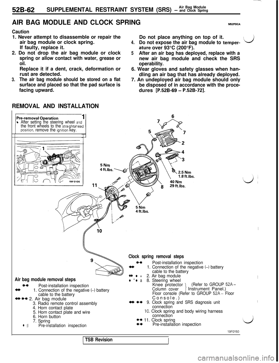
52B-62Air Bag ModuleSUPPLEMENTAL RESTRAINT SYSTEM (SRS) - and Clock Spring
AIR BAG MODULE AND CLOCK SPRINGM52PDCA
Caution1. Never attempt to disassemble or repair the
air bag module or clock spring.
If faulty, replace it.
2. Do not drop the air bag module or clock
spring or allow contact with water, grease or
oil.Replace it if a dent, crack, deformation or
rust are detected.
3.The air bag module should be stored on a flat
surface and placed so that the pad surface isfacing upward.
REMOVAL AND INSTALLATION1
l After setting the steering wheel antthe front wheels to the stralghtaheaposltion. remove the ignition key.5NmDo not place anything on top of it.
4.Do not expose the air bag module to temper-ILJ
ature over 93°C (200°F).
5After an air bag has deployed, replace with anew air bag module and check the SRS
operability.6. Wear gloves and safety glasses when han-
dling an air bag that has already deployed.
7. An undeployed air bag module should only
be disposed of in accordance with the proce-dures
[P.52B-69 - P.52B-721.
Air bag module removal stepsI)4
Post-installation inspection4*1. Connection of the negative (-1 battery
cable to the battery
*I) I)* 2. Air bag module3. Radio remote control assembly
4. Horn contact plate
5. Horn contact plate and wire
6. Horn button
7. Spring
l 4Pre-installation inspection
Clock spring removal steps
I)4Post-installation inspection4*1. Connection of the negative (-1 battery
cable to the battery
+* l +2. Air bag modulel * l a8. Steering wheelKnee protector 1(Refer to GROUP 52A-
Column coverJ Instrument Panel.)Floor console (Refer to GROUP 52A- FloorConsole.)
*I) *+9. Clock spring and SRS diagnosis unitconnection10. Clock spring and body wiring harness
connection
I)* 11. Clock springI)4Pre-installation inspection
I1
I
‘d
1 TSB Revision
19FO150
III
Page 1078 of 1146
52B-68SUPPLEMENTAL RESTRAINT SYSTEM (SRS) - %%%$kgSRS warning
light
/------ r--l
I
19FOO722. INSTALLATION OF AIR BAG MODULE
(1) Arrange the wiring of the horn switch as shown in the
figure at the left, and hook up in place.
(2) Install the air bag module, taking care that no wiring is
vicaught by it.
POST-INSTALLATION INSPECTION(1) After installing the clock spring, the steering wheel, the
column covers and the air bag module, check steering
wheel for noise, binds or difficult operation.
(2) Reconnect the negative battery terminal. Turn the ignition
switch to “ON”. Does the “SRS” warning light illuminate
for about 7 seconds, turn OFF and then remain extin-
guished for at least 45 seconds? If yes, SRS system is
functioning properly. If no, consult page
52B-17.
TSB Revision