Page 1890 of 4087
3. REMOVE VACUUM CONTROL VALVE SET(a) Disconnect the connector from the VSV.
(b) Disconnect the following hoses:(1) Vacuum hose from VSV
(2) Vacuum hose from vacuum pipe
(c) Remove the two nuts and vacuum control valve set.
4. REMOVE VACUUM TANK AND VSV Remove the screw, vacuum hose and VSV from the vacuum
tank.
5. REMOVE OIL DIPSTICK FOR ENGINE
6. DISCONNECT NO. 2 VACUUM PIPE Remove the two nuts and disconnect the vacuum pipe.
7. REMOVE EGR PIPE (a) Loosen the union nut.
(b) Remove the two bolts, EGR pipe and gasket.
8. REMOVE AIR INTAKE CHAMBER (a) Disconnect the following hoses:(1) Vacuum hose from brake booster union
(2) Air hose (from charcoal canister)
(3) Vacuum hose from vacuum pipe
(4) Vacuum sensing hose
(5) Air hose (from PS air control valve)
FI±58
±
EFI SYSTEM
Air Induction System (Acoustic Control Induction System (ACIS)
WhereEverybodyKnowsYourName
Page 1894 of 4087

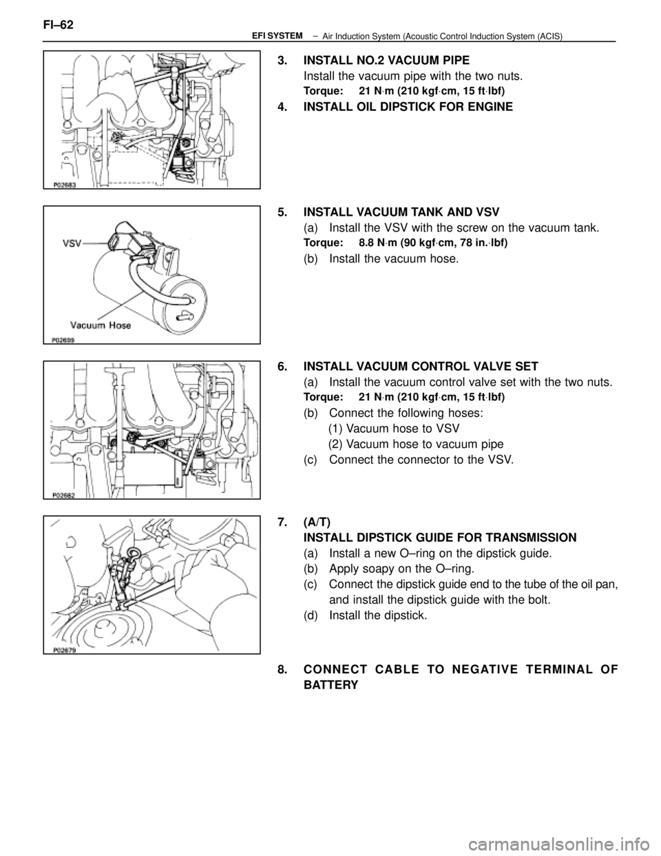
3. INSTALL NO.2 VACUUM PIPEInstall the vacuum pipe with the two nuts.
Torque: 21 N Vm (210 kgf Vcm, 15 ft Vlbf)
4. INSTALL OIL DIPSTICK FOR ENGINE
5. INSTALL VACUUM TANK AND VSV
(a) Install the VSV with the screw on the vacuum tank.
Torque: 8.8 N Vm (90 kgf Vcm, 78 in. Vlbf)
(b) Install the vacuum hose.
6. INSTALL VACUUM CONTROL VALVE SET (a) Install the vacuum control valve set with the two nuts.
Torque: 21 N Vm (210 kgf Vcm, 15 ft Vlbf)
(b) Connect the following hoses:
(1) Vacuum hose to VSV
(2) Vacuum hose to vacuum pipe
(c) Connect the connector to the VSV.
7. (A/T) INSTALL DIPSTICK GUIDE FOR TRANSMISSION
(a) Install a new O±ring on the dipstick guide.
(b) Apply soapy on the O±ring.
(c) Connect the dipstick guide end to the tube of the oil pan,
and install the dipstick guide with the bolt.
(d) Install the dipstick.
8. CONNECT CABLE TO NEGATIVE TERMINAL OF BATTERY
FI±62
±
EFI SYSTEM
Air Induction System (Acoustic Control Induction System (ACIS)
WhereEverybodyKnowsYourName
Page 1896 of 4087
REMOVAL OF FUEL PRESSURE
PULSATION DAMPER
(See Component on page FI±58)
1. DISCONNECT CABLE FROM NEGATIVE TERMINAL OF BATTERY
CAUTION: Work must be started after approx. 20 se-
conds or longer from the time the ignition switch is
turned to the ºLOCKº position and the negative (±) termi-
nal cable is disconnected from the battery.
2. REMOVE UPPER HIGH±TENSION CORD COVER (a) Remove the two mounting bolts.
(b) Disconnect the front side claw groove of the cord coverfrom the claw of the lower cover, and remove the cord
cover.
3. REMOVE LH ENGINE WIRE COVER Remove the two bolts and engine wire cover.
4. REMOVE FUEL PRESSURE PULSATION DAMPER (a) Remove the pulsation damper and upper gasket.
(b) Disconnect the fuel inlet hose from the delivery pipe,and remove the lower gasket. FI±59
EFI SYSTEM
± Fuel System (Fuel Pressure Pulsation Damper)
WhereEverybodyKnowsYourName
Page 1897 of 4087

INSTALLATION OF FUEL PRESSURE
PULSATION DAMPER
(See Components on page FI±58)
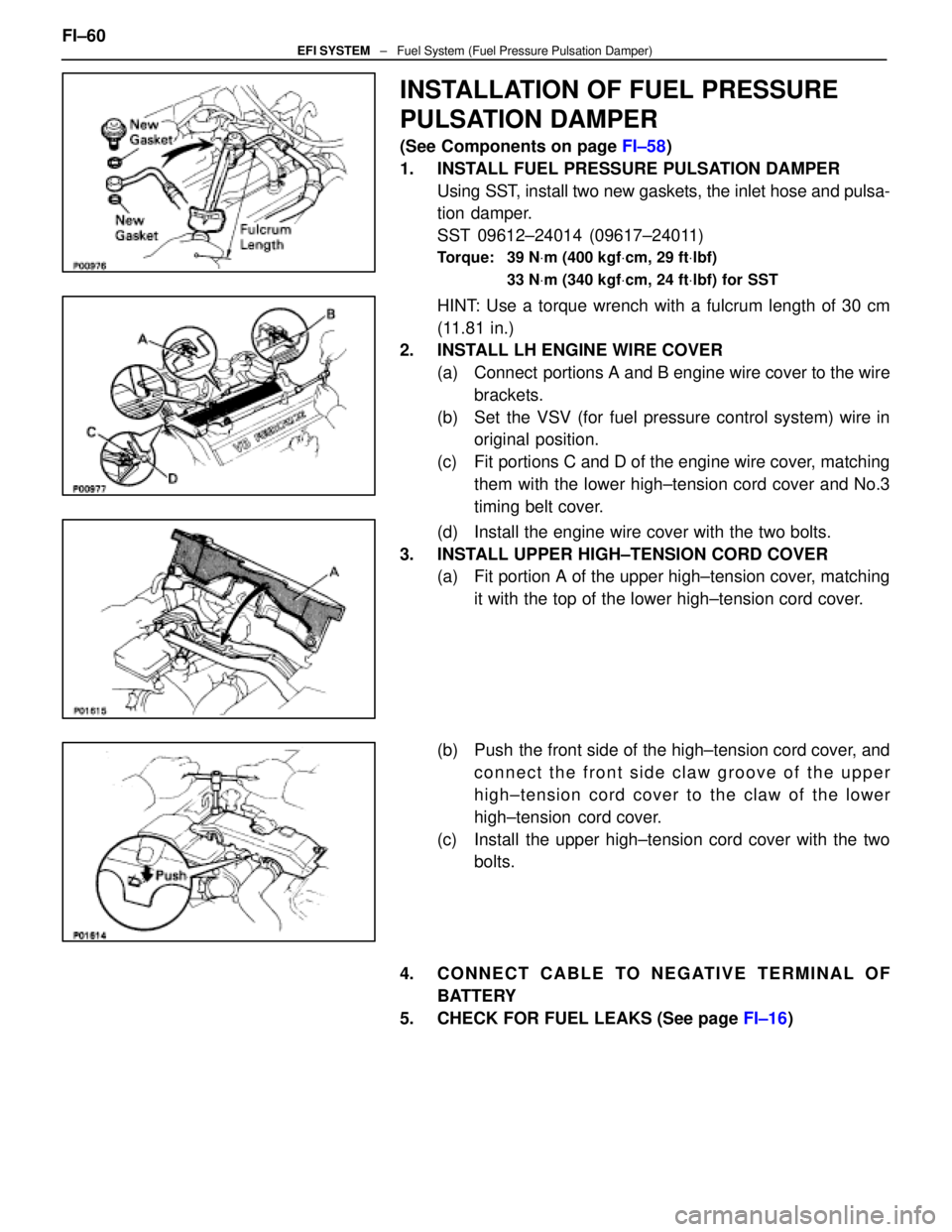
1. INSTALL FUEL PRESSURE PULSATION DAMPER Using SST, install two new gaskets, the inlet hose and pulsa-
tion damper.
SST 09612±24014 (09617±24011)
Torque: 39 N Vm (400 kgf Vcm, 29 ft Vlbf)
33 N Vm (340 kgf Vcm, 24 ft Vlbf) for SST
HINT: Use a torque wrench with a fulcrum length of 30 cm
(11.81 in.)
2. INSTALL LH ENGINE WIRE COVER
(a) Connect portions A and B engine wire cover to the wirebrackets.
(b) Set the VSV (for fuel pressure control system) wire in original position.
(c) Fit portions C and D of the engine wire cover, matching them with the lower high±tension cord cover and No.3
timing belt cover.
(d) Install the engine wire cover with the two bolts.
3. INSTALL UPPER HIGH±TENSION CORD COVER (a) Fit portion A of the upper high±tension cover, matching
it with the top of the lower high±tension cord cover.
(b) Push the front side of the high±tension cord cover, and connect the front side claw groove of the upper
high±tension cord cover to the claw of the lower
high±tension cord cover.
(c) Install the upper high±tension cord cover with the two bolts.
4. CONNECT CABLE TO NEGATIVE TERMINAL OF BATTERY
5. CHECK FOR FUEL LEAKS (See page FI±16)
FI±60
EFI SYSTEM
± Fuel System (Fuel Pressure Pulsation Damper)
WhereEverybodyKnowsYourName
Page 1903 of 4087
EFI Main Relay
INSPECTION OF EFI MAIN RELAY
1. REMOVE EFI MAIN RELAY FROM RELAY BOX IN ENGINE
COMPARTMENT
2. INSPECT EFI MAIN RELAY
A. Inspect relay continuity (a) Using an ohmmeter, check that there is continuitybetween terminals 1 and 3.
(b) Check that there is no continuity between terminals 2 and 4.
If continuity is not as specified, replace the relay.
B. Inspect relay operation (a) Apply battery voltage across terminals 1 and 3.
(b) Using an ohmmeter, check that there is continuitybetween terminals 2 and 4.
If operation is not as specified, replace the relay.
3. REINSTALL EFI MAIN RELAY
FI±64
±
EFI SYSTEM Electronic Control System (EFI main RelaY)
WhereEverybodyKnowsYourName
Page 1906 of 4087
ON±VEHICLE INSPECTION
1. INSPECT THROTTLE BODY(a) Remove the throttle body cover.w Remove the mounting cap nut.
w Loosen the two bolts, and remove the throttle body
cover.
(b) Check that the throttle linkage moves smoothly.
(c) Check the vacuum at each port. w Start the engine.
w Check the vacuum with your finger.
Port nameAt idlingAt 3,000 rpm
PNo vacuumVacuum
*ENo vacuumVacuum
*RNo vacuumVacuum
* Exc. USA Spec.
(d) Reinstall the throttle body cover.
3. INSPECT AND ADJUST DASH POT (DP)
A. Warm up engine Allow the engine to warm up to normal operating tempera-
ture.
B. Check idle speed
Idle speed: 700 + 50 rpm
C. Remove cap, filter and separator from DP FI±67
EFI SYSTEM
± Air Induction System (Throttle Body)
WhereEverybodyKnowsYourName
Page 1907 of 4087
D. Check and adjust DP setting speed(a) Maintain the engine at 2,500 rpm.
(b) Plug the VTV hole with your finger.
(c) Release the throttle valve.
(d) Check that the DP is set.
DP setting speed: 1,500 rpm
(e) Adjust the DP setting speed by turning the DP adjusting
screw.
(f) Repeat steps from (a) to (c), and recheck the DP setting
speed.
E. Reinstall separator, filter and cap to DP HINT: Install the filter with the coarser surface facing the at-
mospheric side (outward).
F. Check VTV operation (a) Maintain the engine at 2,500 rpm.
(b) Release the throttle valve, and check that the enginereturns to idle in a few seconds.
FI±68
EFI SYSTEM
± Air Induction System (Throttle Body)
WhereEverybodyKnowsYourName
Page 1909 of 4087

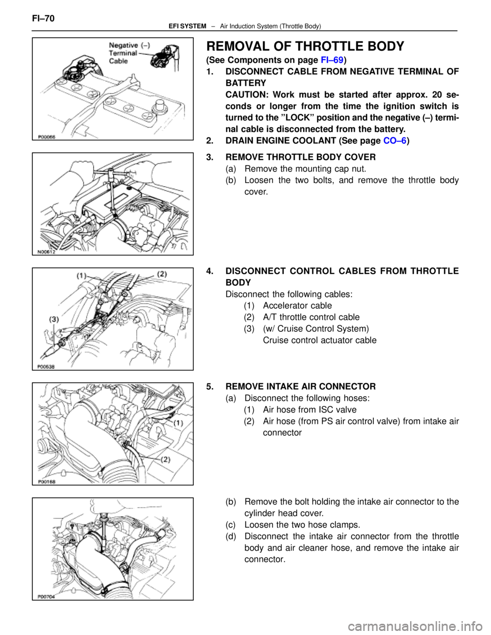
REMOVAL OF THROTTLE BODY
(See Components on page FI±69)
1. DISCONNECT CABLE FROM NEGATIVE TERMINAL OF BATTERY
CAUTION: Work must be started after approx. 20 se-
conds or longer from the time the ignition switch is
turned to the ºLOCKº position and the negative (±) termi-
nal cable is disconnected from the battery.
2. DRAIN ENGINE COOLANT (See page CO±6)
3. REMOVE THROTTLE BODY COVER (a) Remove the mounting cap nut.
(b) Loosen the two bolts, and remove the throttle bodycover.
4. DISCONNECT CONTROL CABLES FROM THROTTLE BODY
Disconnect the following cables:(1) Accelerator cable
(2) A/T throttle control cable
(3) (w/ Cruise Control System)
Cruise control actuator cable
5. REMOVE INTAKE AIR CONNECTOR (a) Disconnect the following hoses:(1) Air hose from ISC valve
(2) Air hose (from PS air control valve) from intake air connector
(b) Remove the bolt holding the intake air connector to the cylinder head cover.
(c) Loosen the two hose clamps.
(d) Disconnect the intake air connector from the throttle body and air cleaner hose, and remove the intake air
connector.
FI±70
EFI SYSTEM
± Air Induction System (Throttle Body)
WhereEverybodyKnowsYourName