Page 3058 of 4087
6. INSTALL UPPER BRACKET
(a) Install the upper bracket with 2 new tapered±head bolts.
(b) Tighten the tapered±head bolts until the bolt heads break off.
7. INSTALL CONNECTOR BRACKET
Torque: 4.9 N Vm (50 kgf Vcm, 43 in. Vlbf)
8. INSTALL NO. 1 PROTECTOR AND NO. 2 PROTECTOR
9. INSTALL TURN SIGNAL BRACKET
Install the turn signal bracket so that its upper surface is par-
allel with upper surface of the capsule of the breakaway
bracket.
10. INSTALL TILT AND TELESCOPIC POSITION SENSORS
SR±36
±
STEERING STEERING COLUMN
WhereEverybodyKnowsYourName
Page 3059 of 4087
11. INSTALL TELESCOPIC SENSOR PLATE
Torque: 4.9 NVm (50 kgf Vcm, 43 in. Vlbf)
12. INSTALL LOWER DUST COVER
(a) Using a press, install the dust seal.
(b) Install the lower dust cover and clip.
13. INSTALL SLIDING YOKE
Align matchmarks and install the sliding yoke to the main
shaft.
Torque: 35 N Vm (360 kgf Vcm, 26 ft Vlbf)
14. INSTALL IGNITION KEY CYLINDER ILLUMINATION
±
STEERING STEERING COLUMNSR±37
WhereEverybodyKnowsYourName
Page 3062 of 4087

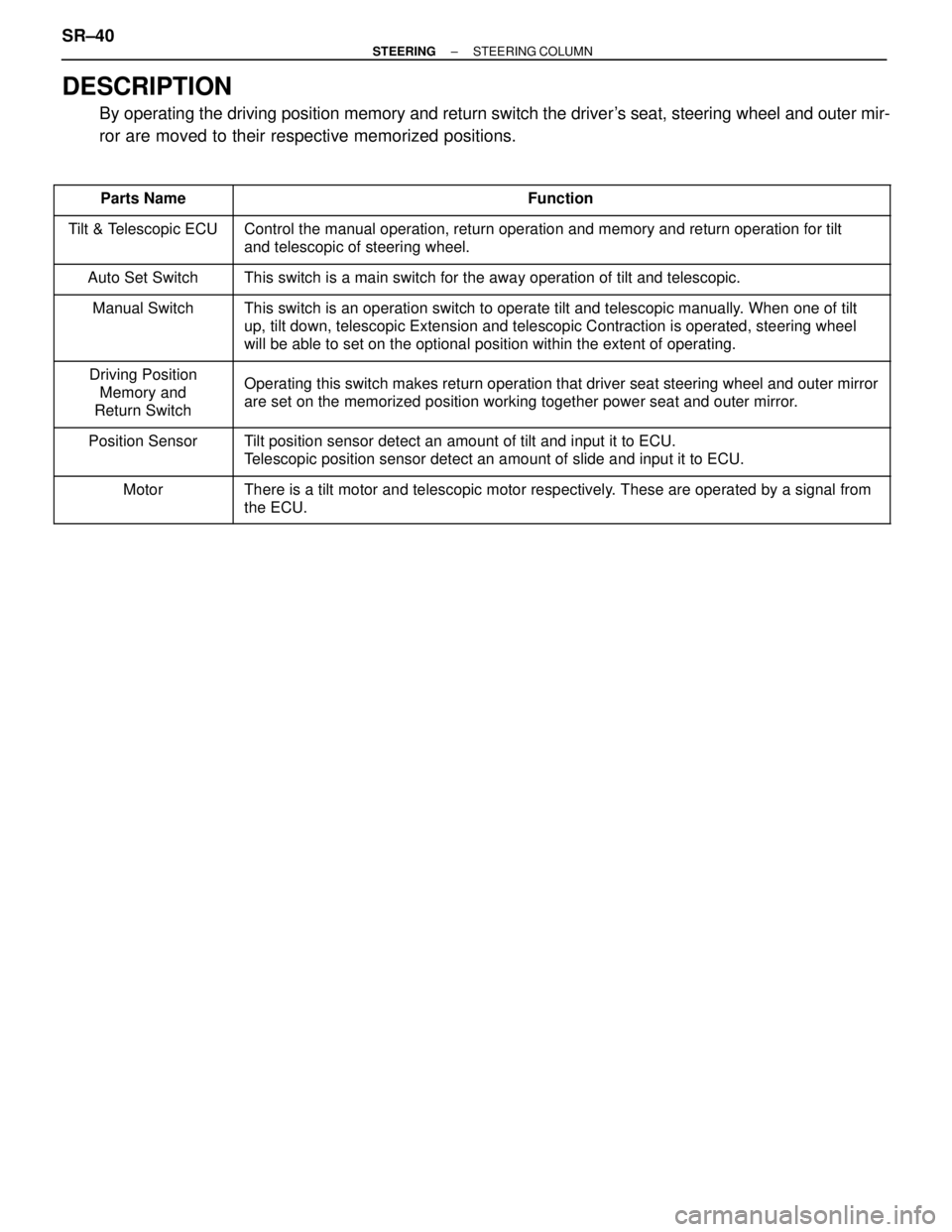
DESCRIPTION
By operating the driving position memory and return switch the driver's seat, steering wheel and outer mir-
ror are moved to their respective memorized positions.
�������� �
�������
��������Parts Name������������������\
����������� �
������������������\
����������
������������������\
�����������Function�������� �
�������
�
�������
��������
Tilt & Telescopic ECU
������������������\
����������� �
������������������\
����������
�
������������������\
����������
������������������\
�����������
Control the manual operation, return operation and memory and return ope\
ration for tilt
and telescopic of steering wheel.
�������� ��������Auto Set Switch������������������\
����������� ������������������\
�����������This switch is a main switch for the away operation of tilt and telescop\
ic.
�������� �
�������
�
�������
��������
Manual Switch������������������\
����������� �
������������������\
����������
�
������������������\
����������
������������������\
�����������
This switch is an operation switch to operate tilt and telescopic manual\
ly. When one of tilt
up, tilt down, telescopic Extension and telescopic Contraction is operat\
ed, steering wheel
will be able to set on the optional position within the extent of operat\
ing.
�������� �
�������
��������
Driving Position
Memory and
Return Switch������������������\
����������� �
������������������\
����������
������������������\
�����������
Operating this switch makes return operation that driver seat steering w\
heel and outer mirror
are set on the memorized position working together power seat and outer \
mirror.
�������� �
�������
��������Position Sensor
������������������\
����������� �
������������������\
����������
������������������\
�����������Tilt position sensor detect an amount of tilt and input it to ECU.
Telescopic position sensor detect an amount of slide and input it to ECU.\
�������� �
�������
��������Motor
������������������\
����������� �
������������������\
����������
������������������\
�����������There is a tilt motor and telescopic motor respectively. These are operated by a signal from
the ECU.
SR±40±
STEERING STEERING COLUMN
WhereEverybodyKnowsYourName
Page 3066 of 4087

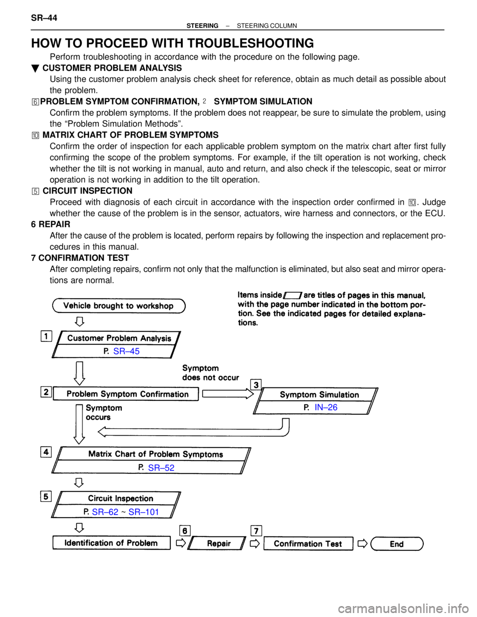
HOW TO PROCEED WITH TROUBLESHOOTING
Perform troubleshooting in accordance with the procedure on the following page.\
� CUSTOMER PROBLEM ANALYSIS
Using the customer problem analysis check sheet for reference, obtain as much detail as possible about
the problem.
� PROBLEM SYMPTOM CONFIRMATION, � SYMPTOM SIMULATION
Confirm the problem symptoms. If the problem does not reappear, be sure to simulate the problem, using
the ªProblem Simulation Methodsº.
� MATRIX CHART OF PROBLEM SYMPTOMS
Confirm the order of inspection for each applicable problem symptom on t\
he matrix chart after first fully
confirming the scope of the problem symptoms. For example, if the tilt operation i\
s not working, check
whether the tilt is not working in manual, auto and return, and also check if the telescopic, seat or mirror
operation is not working in addition to the tilt operation.
� CIRCUIT INSPECTION
Proceed with diagnosis of each circuit in accordance with the inspection order \
confirmed in �. Judge
whether the cause of the problem is in the sensor, actuators, wire harness and connectors, or the ECU.
6 REPAIR
After the cause of the problem is located, perform repairs by following the i\
nspection and replacement pro-
cedures in this manual.
7 CONFIRMATION TEST After completing repairs, confirm not only that the malfunction is eliminated,\
but also seat and mirror opera-
tions are normal.
SR±45
SR±52
SR±62 ~ SR±101 IN±26
SR±44
±
STEERING STEERING COLUMN
WhereEverybodyKnowsYourName
Page 3070 of 4087

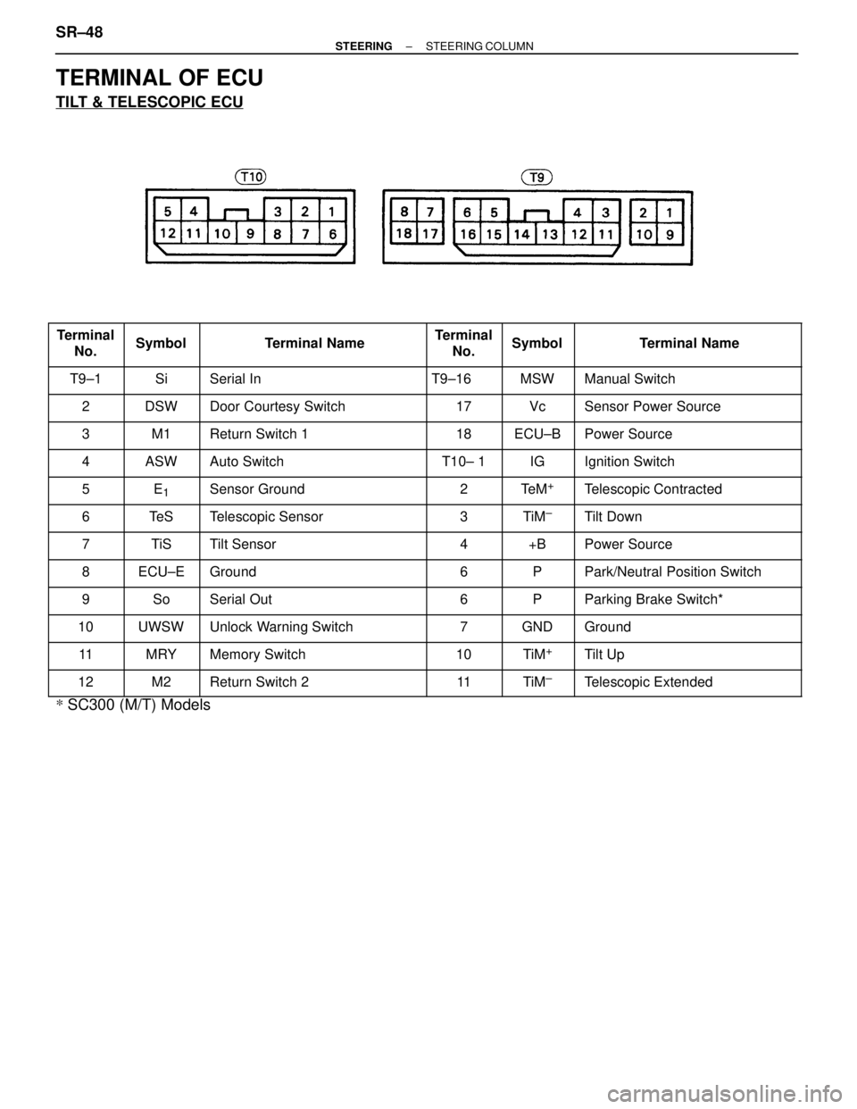
TERMINAL OF ECU
TILT & TELESCOPIC ECU
���� �
���
�
���
����
Terminal
No.
����� �
����
�
����
�����
Symbol
����������� �
����������
�
����������
�����������
Terminal Name
����� �
����
�
����
�����
Terminal
No.
���� �
���
�
���
����
Symbol
������������ �
�����������
�
�����������
������������
Terminal Name
���� ����T9±1����� �����Si����������� �����������Serial In����� �����T9±16���� ����MSW������������ ������������Manual Switch
���� ����2����� �����DSW����������� �����������Door Courtesy Switch����� �����17���� ����Vc������������ ������������Sensor Power Source
���� ����3����� �����M1����������� �����������Return Switch 1����� �����18���� ����ECU±B������������ ������������Power Source���� �
���
����4
����� �
����
�����ASW
����������� �
����������
�����������Auto Switch
����� �
����
�����T10± 1
���� �
���
����IG
������������ �
�����������
������������Ignition Switch
���� ����5����� �����E1����������� �����������Sensor Ground����� �����2���� ����Te M+������������ ������������Telescopic Contracted
���� ����6����� �����Te S����������� �����������Telescopic Sensor����� �����3���� ����TiM±������������ ������������Tilt Down
���� �
���7����� �
����TiS����������� �
����������Tilt Sensor����� �
����4���� �
���+B������������ �
�����������Power Source���� �
���
����8
����� �
����
�����ECU±E
����������� �
����������
�����������Ground
����� �
����
�����6
���� �
���
����P
������������ �
�����������
������������Park/Neutral Position Switch
���� ����9����� �����So����������� �����������Serial Out����� �����6���� ����P������������ ������������Parking Brake Switch*
���� ����10����� �����UWSW����������� �����������Unlock Warning Switch����� �����7���� ����GND������������ ������������Ground���� �
���
����11����� �
����
�����MRY����������� �
����������
�����������Memory Switch����� �
����
�����10���� �
���
����TiM+������������ �
�����������
������������Tilt Up
���� ����12����� �����M2����������� �����������Return Switch 2����� �����11���� ����TiM±������������ ������������Telescopic Extended
*
SC300 (M/T) Models
SR±48
±
STEERING STEERING COLUMN
WhereEverybodyKnowsYourName
Page 3084 of 4087
SR±52).
IN±33).
WIRING DIAGRAM
CIRCUIT INSPECTION
ECU Power Source Circuit
CIRCUIT DESCRIPTION
The ECU power source also supplies power to the CPU and sensor, etc. Power is supplied to the ECU even
when the ignition switch is off.
DIAGNOSTIC CHARTDIAGNOSTIC CHART
SR±62±
STEERING STEERING COLUMN
WhereEverybodyKnowsYourName
Page 3088 of 4087
DTC53Short in Squib Circuit (Between P+ Wire Harness
P
± Wire Harness)
CIRCUIT DESCRIPTION
The squib circuit consists of the center airbag sensor assembly, (squib). It causes the SRS to deploy when the
SRS deployment conditions are satisfied.
For details of the function of each component, see FUNCTION OF COMPONENTS o\
n page RS±10. Diagnostic
trouble code 53 is recorded when an short is detected in the P
+ wire harness and P± wire harness of the squib
circuit.
DTC No.Diagnosis
53
� Short circuit between P+ wire harness and P± wire harness of squib.
� Squib malfunction.
� Center airbag Sensor Assembly malfunction.
DIAGNOSTIC CHARTDIAGNOSTIC CHART
RS±110±
SUPPLEMENTAL RESTRAINT SYSTEM TROUBLESHOOTING
WhereEverybodyKnowsYourName
Page 3090 of 4087
OKNG
INSPECTION PROCEDURE
1Preparation.
P1. Disconnect battery negative (±) terminal cable, andwait at least 90 seconds.
2. Remove steering wheel pad (See page RS±19).
3. Disconnect connectors of front passenger airbag assembly (See page RS±32).
Caution: Store the steering wheel pad with the
surface facing upward.
2Check P squib circuit.
C
OK
Measure resistance between P+ and P± on center air-
bag sensor assembly side of connector between center
airbag sensor assembly and front passenger airbag as-
sembly.
Resistance: 1 k � or higher
Go to step �.
RS±112
±
SUPPLEMENTAL RESTRAINT SYSTEM TROUBLESHOOTING
WhereEverybodyKnowsYourName