Page 2811 of 4087

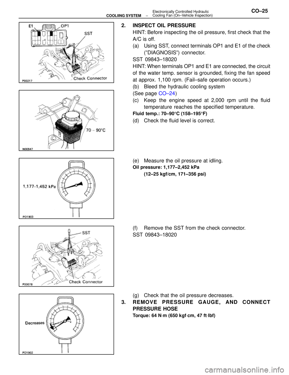
2. INSPECT OIL PRESSUREHINT: Before inspecting the oil pressure, first check that the
A/C is off.
(a) Using SST, connect terminals OP1 and E1 of the check(ºDIAGNOSISº) connector.
SST 09843±18020
HINT: When terminals OP1 and E1 are connected, the circuit
of the water temp. sensor is grounded, fixing the fan speed
at approx. 1,100 rpm. (Fail±safe operation occurs.)
(b) Bleed the hydraulic cooling system
(See page CO±24)
(c) Keep the engine speed at 2,000 rpm until the fluid temperature reaches the specified temperature.
Fluid temp.: 70±90 5C (158±195 5F)
(d) Check the fluid level is correct.
(e) Measure the oil pressure at idling.
Oil pressure: 1,177±2,452 kPa
(12±25 kgf/cm, 171±356 psi)
(f) Remove the SST from the check connector.
SST 09843±18020
(g) Check that the oil pressure decreases.
3. REMOVE PRESSURE GAUGE, AND CONNECT PRESSURE HOSE
Torque: 64 N Vm (650 kgf Vcm, 47 ft Vlbf)
±
COOLIING SYSTEM Electronically Controlled Hydraulic
Cooling Fan (On±Vehicle Inspection)CO±25
WhereEverybodyKnowsYourName
Page 2816 of 4087

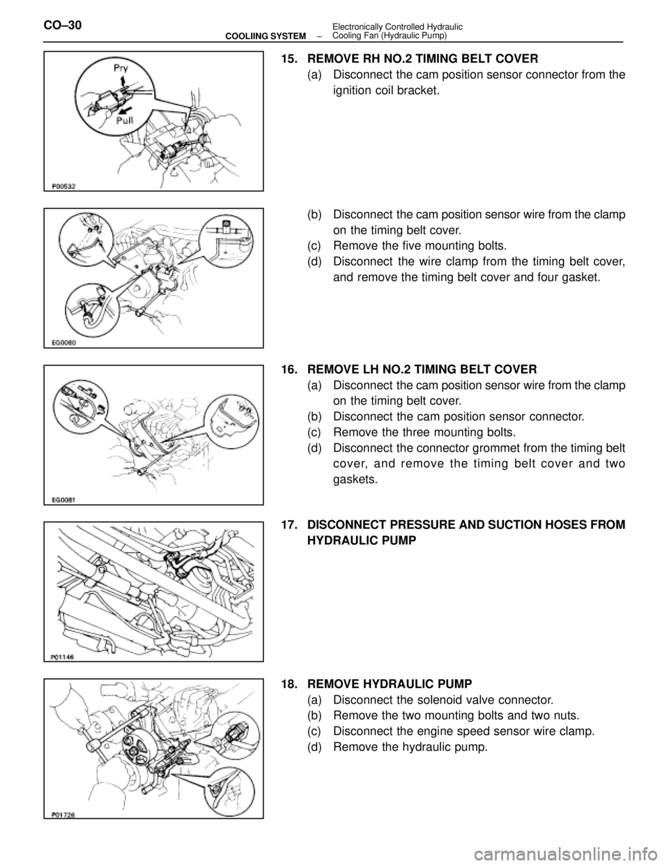
15. REMOVE RH NO.2 TIMING BELT COVER(a) Disconnect the cam position sensor connector from theignition coil bracket.
(b) Disconnect the cam position sensor wire from the clamp
on the timing belt cover.
(c) Remove the five mounting bolts.
(d) Disconnect the wire clamp from the timing belt cover,
and remove the timing belt cover and four gasket.
16. REMOVE LH NO.2 TIMING BELT COVER (a) Disconnect the cam position sensor wire from the clamp
on the timing belt cover.
(b) Disconnect the cam position sensor connector.
(c) Remove the three mounting bolts.
(d) Disconnect the connector grommet from the timing belt cover, and remove the timing belt cover and two
gaskets.
17. DISCONNECT PRESSURE AND SUCTION HOSES FROM HYDRAULIC PUMP
18. REMOVE HYDRAULIC PUMP (a) Disconnect the solenoid valve connector.
(b) Remove the two mounting bolts and two nuts.
(c) Disconnect the engine speed sensor wire clamp.
(d) Remove the hydraulic pump.
CO±30
±
COOLIING SYSTEM Electronically Controlled Hydraulic
Cooling Fan (Hydraulic Pump)
WhereEverybodyKnowsYourName
Page 2828 of 4087

INSTALLATION OF HYDRAULIC PUMP
(See Components on page CO±26)
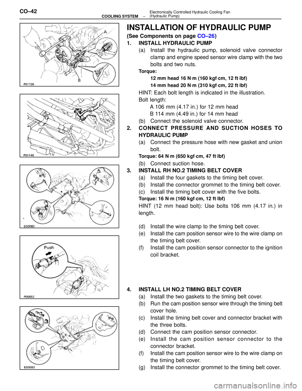
1. INSTALL HYDRAULIC PUMP (a) Install the hydraulic pump, solenoid valve connector
clamp and engine speed sensor wire clamp with the two
bolts and two nuts.
Torque:
12 mm head 16 N Vm (160 kgf Vcm, 12 ft Vlbf)
14 mm head 20 N Vm (310 kgf Vcm, 22 ft Vlbf)
HINT: Each bolt length is indicated in the illustration.
Bolt length:
A 106 mm (4.17 in.) for 12 mm head
B 114 mm (4.49 in.) for 14 mm head
(b) Connect the solenoid valve connector.
2. CONNECT PRESSURE AND SUCTION HOSES TO HYDRAULIC PUMP
(a) Connect the pressure hose with new gasket and unionbolt.
Torque: 64 N Vm (650 kgf Vcm, 47 ft Vlbf)
(b) Connect suction hose.
3. INSTALL RH NO.2 TIMING BELT COVER
(a) Install the four gaskets to the timing belt cover.
(b) Install the connector grommet to the timing belt cover.
(c) Install the timing belt cover with the five bolts.
Torque: 16 N Vm (160 kgf Vcm, 12 ft Vlbf)
HINT (12 mm head bolt): Use bolts 106 mm (4.17 in.) in
length.
(d) Install the wire clamp to the timing belt cover.
(e) Install the cam position sensor wire to the wire clamp on
the timing belt cover.
(f) Install the cam position sensor connector to the ignition coil bracket.
4. INSTALL LH NO.2 TIMING BELT COVER (a) Install the two gaskets to the timing belt cover.
(b) Run the cam po sition sensor wire through the timing belt
cover hole.
(c) Install the timing belt cover and connector bracket with the three bolts.
(d) Connect the cam position sensor connector.
(e) In sta ll th e ca m po sitio n se n so r c onnector to the
connector bracket.
(f) Install the cam position sensor wire to the wire clamp on
the timing belt cover.
(g) Install the connector grommet to the timing belt cover.
CO±42
±
COOLIING SYSTEM Electronically Controlled Hydraulic Cooling Fan
(Hydraulic Pump)
WhereEverybodyKnowsYourName
Page 2834 of 4087
REMOVAL OF HYDRAULIC MOTOR
(See Components on page CO±47)
1. REMOVE BATTERY CAUTION: Work must be started after approx. 20 se-
conds or longer from the time the ignition switch is
turned to the ºLOCKº position and the negative (±) termi-
nal cable is disconnected from the battery.
2. REMOVE ENGINE UNDER COVERS
3. DRAIN ENGINE COOLANT (See page CO±6)
4. REMOVE RADIATOR RESERVOIR TANK (a) Disconnect the coolant level sensor connector.
(b) Disconnect the following hoses:(1) Reservoir hose from water inlet housing
(2) Reservoir hose from radiator
(c) Remove the two bolts and reservoir tank bracket.
(d) Disconnect the reservoir tank from the reservoir tank bracket, and remove the reservoir tank.
5. DISCONNECT HOSES Disconnect the following hoses:(1) Upper radiator hose from radiator
(2) Pressure hose from hydraulic motor
(3) Return hose from hydraulic motor
CO±48
±
COOLIING SYSTEM Electronically Controlled Hydraulic Cooling Fan
(Hydraulic Motor)
WhereEverybodyKnowsYourName
Page 2835 of 4087
6. DISCONNECT COOLING FAN INLET PIPE FROM FANSHROULD
Remove the two bolts, brackets and bushings, and discon-
nect the inlet pipe.
7. DISCONNECT COOLING FAN RESERVOIR TANK FROM FAN SHROULD
(a) Disconnect the suction hose from the clamp on the fanshrould.
(b) Remove the four bolts, and disconnect the reservoir tank.
8. REMOVE RADIATOR FAN SHROULD (a) Disconnect the wire clamp (for temperature sensor)from the radiator fan shrould.
(b) Remove the four bolts, and disconnect the fan shrould from the radiator.
(c) Slightly lift the fan shrould, and disconnect the two oil cooler hoses (for cooling fan) from the hose clamp on
the fan shrould.
(d) Remove the fan shrould.
±
COOLIING SYSTEM Electronically Controlled Hydraulic Cooling Fan
(Hydraulic Motor)CO±49
WhereEverybodyKnowsYourName
Page 2843 of 4087
7. INSTALL RADIATOR RESERVOIR TANK(a) Install the reservoir tank to the reservoir tank bracket.
(b) Install the reservoir tank bracket with two bolts.
Torque: 4.9 N Vm (50 kgf Vcm, 43 in. Vlbf)
(c) Connect the following hoses:
(1) Reservoir hose to water inlet housing
(2) Reservoir hose to radiator
(d) Connect the coolant level sensor connector.
8. INSTALL BATTERY
9. FILL ENGINE WITH COOLANT (See page CO±7)
10. FILL COOLING FAN RESERVOIR TANK WITH FLUID
(See pages CO±23 and 24)
11. START ENGINE AND CHECK FOR LEAKS
12. INSTALL ENGINE UNDER COVER
±
COOLIING SYSTEM Electronically Controlled Hydraulic Cooling Fan
(Hydraulic Motor)CO±57
WhereEverybodyKnowsYourName
Page 2848 of 4087
(Water Temperature Sensor)
COMPONENTS FOR REMOVAL AND
INSTALLATION
INSPECTION OF WATER TEMPERATURE
SENSOR
1. DISCONNECT CABLE FROM NEGATIVE TERMINAL OFBATTERY
CAUTION: Work must be started after 20 seconds or
longer from the time the ignition switch is turned to the
ºLOCKº position and the negative (±) terminal cable is
disconnected from the battery.
2. REMOVE ENGINE UNDER COVER
3. DRAIN ENGINE COOLANT (See page CO±6)
4. REMOVE WATER TEMPERATURE SENSOR (a) Disconnect the water temperature sensor connector.
(b) Remove the water temperature sensor from left side ofthe radiator lower tank.
(c) Remove the O±ring from the water temperature sensor.
CO±62
±
COOLIING SYSTEM Electronically Controlled Hydraulic
Cooling Fan (Electronic Control Parts)
WhereEverybodyKnowsYourName
Page 2849 of 4087

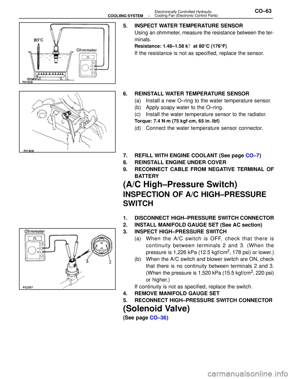
5. INSPECT WATER TEMPERATURE SENSORUsing an ohmmeter, measure the resistance between the ter-
minals.
Resistance: 1.48±1.58 k � at 80 5C (176 5F)
If the resistance is not as specified, replace the sensor.
6. REINSTALL WATER TEMPERATURE SENSOR (a) Install a new O±ring to the water temperature sensor.
(b) Apply soapy water to the O±ring.
(c) Install the water temperature sensor to the radiator.
Torque: 7.4 N Vm (75 kgf Vcm, 65 in. Vlbf)
(d) Connect the water temperature sensor connector.
7. REFILL WITH ENGINE COOLANT (See page CO±7)
8. REINSTALL ENGINE UNDER COVER
9. RECONNECT CABLE FROM NEGATIVE TERMINAL OF BATTERY
(A/C High±Pressure Switch)
INSPECTION OF A/C HIGH±PRESSURE
SWITCH
1. DISCONNECT HIGH±PRESSURE SWITCH CONNECTOR
2. INSTALL MANIFOLD GAUGE SET (See AC section)
3. INSPECT HIGH±PRESSURE SWITCH(a) Wh e n th e A/C switch is OFF, ch e ck th a t th e re iscontinuity between terminals 2 and 3. (When the
pressure is 1,226 kPa (12.5 kgf/cm
2, 178 psi) or lower.)
(b) When the A/C switch and blower switch are ON, check
that there is no continuity between terminals 2 and 3.
(When the pressure is 1,520 kPa (15.5 kgf/cm
2, 220 psi)
or higher.)
If continuity is not as specified, replace the switch.
4. REMOVE MANIFOLD GAUGE SET
5. RECONNECT HIGH±PRESSURE SWITCH CONNECTOR
(Solenoid Valve)
(See page CO±36)
±
COOLIING SYSTEM Electronically Controlled Hydraulic
Cooling Fan (Electronic Control Parts)CO±63
WhereEverybodyKnowsYourName