Page 2934 of 4087
SR±52).
IN±33).
WIRING DIAGRAM
Tilt Position Sensor Circuit
CIRCUIT DESCRIPTION
The tilt position is sent to the ECU as a voltage signal from the position \
sensor.
A constant 5 V is supplied to terminal 1 of sensor.
The voltage at terminal 3 varies with position and is input to the ECU.
DIAGNOSTIC CHARTDIAGNOSTIC CHART
SR±72±
STEERING STEERING COLUMN
WhereEverybodyKnowsYourName
Page 2935 of 4087

NGOK
OKNG
OKNG
INSPECTION PROCEDURE
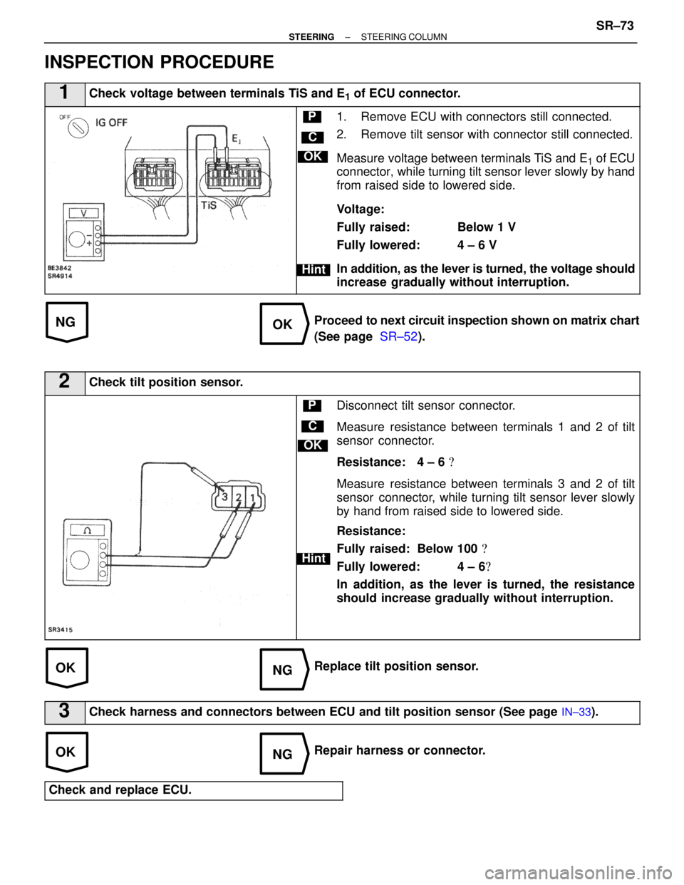
1Check voltage between terminals TiS and E1 of ECU connector.
C
OK
Hint
P1. Remove ECU with connectors still connected.
2. Remove tilt sensor with connector still connected.
Measure voltage between terminals TiS and E
1 of ECU
connector, while turning tilt sensor lever slowly by hand
from raised side to lowered side.
Voltage:
Fully raised: Below 1 V
Fully lowered: 4 ± 6 V
In addition, as the lever is turned, the voltage should
increase gradually without interruption.
Proceed to next circuit inspection shown on matrix chart
(See page SR±52).
2Check tilt position sensor.
C
OK
Hint
PDisconnect tilt sensor connector.
Measure resistance between terminals 1 and 2 of tilt
sensor connector.
Resistance: 4 ± 6 �
Measure resistance between terminals 3 and 2 of tilt
sensor connector, while turning tilt sensor lever slowly
by hand from raised side to lowered side.
Resistance:
Fully raised: Below 100 �
Fully lowered: 4 ± 6 �
In addition, as the lever is turned, the resistance
should increase gradually without interruption.
Replace tilt position sensor.
3Check harness and connectors between ECU and tilt position sensor (See \
page IN±33).
Repair harness or connector.
Check and replace ECU.
±
STEERING STEERING COLUMNSR±73
WhereEverybodyKnowsYourName
Page 2936 of 4087
SR±52).
IN±33).
WIRING DIAGRAM
Telescopic Position Sensor Circuit
CIRCUIT DESCRIPTION
The telescopic position is sent to the ECU as a voltage signal from the pos\
ition sensor.
A constant 5 V is supplied to terminal 6 of the sensor.
The voltage at terminal 5 varies with position and is input to the ECU.
DIAGNOSTIC CHARTDIAGNOSTIC CHART
SR±76±
STEERING STEERING COLUMN
WhereEverybodyKnowsYourName
Page 2937 of 4087

NGOK
OKNG
OKNG
INSPECTION PROCEDURE
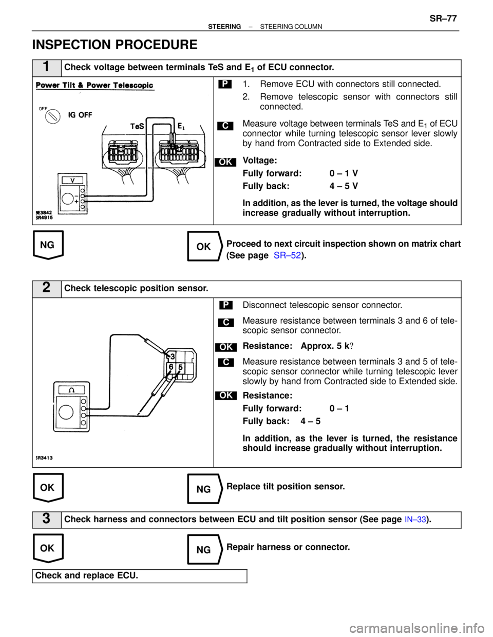
1Check voltage between terminals TeS and E1 of ECU connector.
C
OK
P1. Remove ECU with connectors still connected.
2. Remove telescopic sensor with connectors stillconnected.
Measure voltage between terminals TeS and E
1 of ECU
connector while turning telescopic sensor lever slowly
by hand from Contracted side to Extended side.
Voltage:
Fully forward: 0 ± 1 V
Fully back: 4 ± 5 V
In addition, as the lever is turned, the voltage should
increase gradually without interruption.
Proceed to next circuit inspection shown on matrix chart
(See page SR±52).
2Check telescopic position sensor.
C
OK
P
OK
C
Disconnect telescopic sensor connector.
Measure resistance between terminals 3 and 6 of tele-
scopic sensor connector.
Resistance: Approx. 5 k �
Measure resistance between terminals 3 and 5 of tele-
scopic sensor connector while turning telescopic lever
slowly by hand from Contracted side to Extended side.
Resistance:
Fully forward: 0 ± 1 �
Fully back: 4 ± 5 �
In addition, as the lever is turned, the resistance
should increase gradually without interruption.
Replace tilt position sensor.
3Check harness and connectors between ECU and tilt position sensor (See \
page IN±33).
Repair harness or connector.
Check and replace ECU.
±
STEERING STEERING COLUMNSR±77
WhereEverybodyKnowsYourName
Page 3020 of 4087

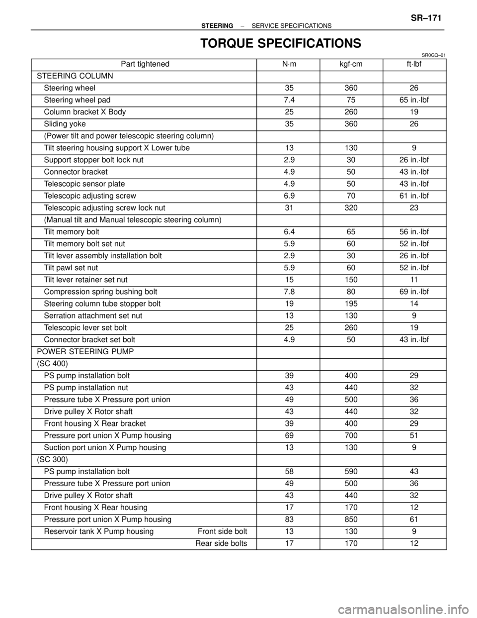
TORQUE SPECIFICATIONS
SR0GQ±01������������������\
�� ������������������\
��Part tightened������ ������NVm������ ������kgf Vcm������� �������ft Vlbf������������������\
�� ������������������\
��STEERING COLUMN������ ������������ ������������� �������
������������������\
�� ������������������\
��Steering wheel������ ������35������ ������360������� �������26������������������\
�� ������������������\
��Steering wheel pad������ ������7.4������ ������75������� �������65 in. Vlbf������������������\
�� ������������������\
��Column bracket X Body������ ������25������ ������260������� �������19������������������\
�� ������������������\
��Sliding yoke������ ������35������ ������360������� �������26������������������\
�� ������������������\
��(Power tilt and power telescopic steering column)������ ������������ ������������� �������
������������������\
�� ������������������\
��Tilt steering housing support X Lower tube������ ������13������ ������130������� �������9������������������\
�� ������������������\
��Support stopper bolt lock nut������ ������2.9������ ������30������� �������26 in. Vlbf������������������\
�� ������������������\
��Connector bracket������ ������4.9������ ������50������� �������43 in. Vlbf������������������\
�� ������������������\
��Telescopic sensor plate������ ������4.9������ ������50������� �������43 in. Vlbf������������������\
�� ������������������\
��Telescopic adjusting screw������ ������6.9������ ������70������� �������61 in. Vlbf������������������\
�� ������������������\
��Telescopic adjusting screw lock nut������ ������31������ ������320������� �������23������������������\
�� ������������������\
��(Manual tilt and Manual telescopic steering column)������ ������������ ������������� �������
������������������\
�� ������������������\
��Tilt memory bolt������ ������6.4������ ������65������� �������56 in. Vlbf������������������\
�� ������������������\
��Tilt memory bolt set nut������ ������5.9������ ������60������� �������52 in. Vlbf������������������\
�� ������������������\
��Tilt lever assembly installation bolt������ ������2.9������ ������30������� �������26 in. Vlbf������������������\
�� ������������������\
��Tilt pawl set nut������ ������5.9������ ������60������� �������52 in. Vlbf������������������\
�� ������������������\
��Tilt lever retainer set nut������ ������15������ ������150������� �������11������������������\
�� ������������������\
��Compression spring bushing bolt������ ������7.8������ ������80������� �������69 in. Vlbf������������������\
�� ������������������\
��Steering column tube stopper bolt������ ������19������ ������195������� �������14������������������\
�� ������������������\
��Serration attachment set nut������ ������13������ ������130������� �������9������������������\
�� ������������������\
��Telescopic lever set bolt������ ������25������ ������260������� �������19������������������\
�� ������������������\
��Connector bracket set bolt������ ������4.9������ ������50������� �������43 in. Vlbf������������������\
�� ������������������\
��POWER STEERING PUMP������ ������������ ������������� �������
������������������\
�� ������������������\
��(SC 400)������ ������������ ������������� �������
������������������\
�� ������������������\
��PS pump installation bolt������ ������39������ ������400������� �������29������������������\
�� ������������������\
��PS pump installation nut������ ������43������ ������440������� �������32������������������\
�� ������������������\
��Pressure tube X Pressure port union������ ������49������ ������500������� �������36������������������\
�� ������������������\
��Drive pulley X Rotor shaft������ ������43������ ������440������� �������32������������������\
�� ������������������\
��Front housing X Rear bracket������ ������39������ ������400������� �������29������������������\
�� ������������������\
��Pressure port union X Pump housing������ ������69������ ������700������� �������51������������������\
�� ������������������\
��Suction port union X Pump housing������ ������13������ ������130������� �������9������������������\
�� ������������������\
��(SC 300)������ ������������ ������������� �������
������������������\
�� ������������������\
��PS pump installation bolt������ ������58������ ������590������� �������43������������������\
�� ������������������\
��Pressure tube X Pressure port union������ ������49������ ������500������� �������36������������������\
�� ������������������\
��Drive pulley X Rotor shaft������ ������43������ ������440������� �������32������������������\
�� ������������������\
��Front housing X Rear housing������ ������17������ ������170������� �������12������������������\
�� ������������������\
��Pressure port union X Pump housing������ ������83������ ������850������� �������61������������������\
�� ������������������\
��Reservoir tank X Pump housing Front side bolt������ ������13������ ������130������� �������9������������������\
�� ������������������\
��Rear side bolts������ ������17������ ������170������� �������12
±
STEERING SERVICE SPECIFICATIONSSR±171
WhereEverybodyKnowsYourName
Page 3026 of 4087
STEERING COLUMN
DESCRIPTION
SR0EA±02
There are two types of steering column, the manual tilt/manual telescopic one\
, and the power tilt/power
telescopic one.
SR0EB±02
OPERATION
POWER TILT OPERATIONThe power tilt mechanism consists of the control gear assembly, tilt motor, tilt position sensor, tilt and tele-
scopic switch, unlock warning switch and tilt and telescopic ECU.
The control gear assembly consists of the worm wheel, tilt gear, tilt worm and slider. Rotation of the tilt motor
moves the slider towards the tilt worm. The column upper tube is integrated w\
ith the slider and is rotated
up and down by movement of the slider.
SR±4
±
STEERING STEERING COLUMN
WhereEverybodyKnowsYourName
Page 3027 of 4087
POWER TELESCOPIC OPERATION
SR0EC±02
The power telescopic mechanism is composed of the control gear assembly, telescopic motor, telescopic
position sensor, tilt and telescopic switch, unlock warning switch and tilt and telesco\
pic ECU.
The control gear assembly is composed of the worm wheel, telescopic scre\
w and slider. Rotation of the
telescopic motor moves the slider in the direction of the telescopic screw axis. The\
sliding tube is integrated
with the slider and is moved forward and backward by movement of the slider.
±
STEERING STEERING COLUMNSR±5
WhereEverybodyKnowsYourName
Page 3051 of 4087
STEERING COLUMN DISASSEMBLY
SR0EL±04
NOTICE: When placing the breakaway bracket in a vise during
disassembly or assembly of the steering column, use alumi-
num, etc. to prevent scratches to the tip of the capsule.
1. REMOVE IGNITION KEY CYLINDER ILLUMINATION
2. REMOVE SLIDING YOKE Place matchmarks on the sliding yoke and main shaft.
3. REMOVE LOWER DUST COVER
(a) Remove the clip and dust cover.
(b) Using a screwdriver, remove the dust seal.
4. REMOVE TELESCOPIC POSITION SENSOR PLATE
5. REMOVE TILT AND TELESCOPIC POSITION SENSORS
±
STEERING STEERING COLUMNSR±29
WhereEverybodyKnowsYourName