Page 360 of 4087
IN±33
WIRING DIAGRAM
TT Terminal Circuit
CIRCUIT DESCRIPTION
Checks of ECM input and output signals related to the throttle position sensor\
brakes, shift position and
other circuits can be performed by measuring the voltages at terminal T
T of the DLC1.
DIAGNOSTIC CHARTDIAGNOSTIC CHART
AT±120±
A304E (1UZ±FE) AUTOMATIC TRANSMISSION TROUBLESHOOTING
WhereEverybodyKnowsYourName
Page 363 of 4087

TORQUE SPECIFICATION
AT07F±04������������������\
�� ������������������\
��Part tightened������ ������NVm������� �������kgf Vcm������ ������ft Vlbf������������������\
�� �
������������������\
�
������������������\
��Engine x Transmission
������ �
�����
������64
������� �
������
�������650
������ �
�����
������47
������������������\
�� ������������������\
��Rear mounting x Body������ ������25������� �������260������ ������19
������������������\
�� ������������������\
��Rear mounting x Extension housing������ ������25������� �������250������ ������18
������������������\
�� ������������������\
��Transmission housing x Transmission case 14 mm (0.55 in.)������ ������34������� �������345������ ������25
������������������\
�� ������������������\
��17 mm (0.67 in.)������ ������57������� �������580������ ������42
������������������\
�� ������������������\
��Extension housing x Transmission case������ ������34������� �������345������ ������25
������������������\
�� ������������������\
��Valve body x Transmission case������ ������10������� �������100������ ������7
������������������\
�� ������������������\
��Oil strainer������ ������10������� �������100������ ������7
������������������\
�� ������������������\
��Oil pan������ ������7.4������� �������75������ ������65 in.
Vlbf������������������\
�� ������������������\
��No.1 vehicle speed sensor������ ������16������� �������160������ ������12������������������\
�� �
������������������\
�
������������������\
��No.2 vehicle speed sensor������ �
�����
������5.4������� �
������
�������55������ �
�����
������48 in.
Vlbf
������������������\
�� ������������������\
��Solenoid wiring stopper plate������ ������5.4������� �������55������ ������48 in. Vlbf
������������������\
�� ������������������\
��O/D direct clutch speed sensor������ ������5.4������� �������55������ ������48 in. Vlbf
������������������\
�� ������������������\
��Transmission output flange������ ������123������� �������1,250������ ������90
������������������\
�� ������������������\
��Throttle cable x Transmission case������ ������5.4������� �������55������ ������48 in. Vlbf
������������������\
�� ������������������\
��Union������ ������29������� �������300������ ������22
������������������\
�� ������������������\
��Cooler pipe union nut������ ������34������� �������350������ ������25
������������������\
�� ������������������\
��Drive plate x Crankshaft������ ������99������� �������1,000������ ������72
������������������\
�� ������������������\
��Torque converter clutch x Drive plate������ ������33������� �������340������ ������25������������������\
�� ������������������\
��Park/Neutral position switch Bolt������ ������13������� �������130������ ������9������������������\
�� ������������������\
��Nut������ ������6.9������� �������70������ ������61 in. Vlbf������������������\
�� �
������������������\
�
������������������\
��Control shaft lever
������ �
�����
������16
������� �
������
�������160
������ �
�����
������12
±
A340E (1UZ±FE) AUTOMATIC TRANSMISSION SERVICE SPECIFICATIONSAT±123
WhereEverybodyKnowsYourName
Page 382 of 4087
VALVE BODY
VALVE BODY REMOVAL
AT0GG±02
1. DRAIN ATF
2. REMOVE FRONT EXHAUST PIPE(See pages EG±204)
3. REMOVE OIL PAN
(a) Remove the 19 bolts.
(b) Install the blade of SST between the transmission case and oil pan, cut off applied sealer.
SST 09032±00100
NOTICE: Be careful not to damage the oil pan flange.
4. EXAMINE PARTICLES IN PANRemove the magnets and use them to collect steel particles.
Carefully look at the foreign matter and particles in the pan
and on the magnets to anticipate the type of wear you will find
in the transmission:
Steel (magnetic) 0 bearing, gear and clutch plate wear
Brass (non±magnetic) 0 bushing wear
5. REMOVE OIL STRAINER Remove the 3 bolts holding the oil strainer to the valve body.
6. REMOVE SOLENOID WIRING
(a) Remove the 2 bolts and the clamp.
(b) Disconnect the 4 connectors from the solenoid valves.
±
A304E (1UZ±FE) AUTOMATIC TRANSMISSION VALVE BODYAT±19
WhereEverybodyKnowsYourName
Page 540 of 4087
Wiring and Connector Diagrams
BE±148±
BODY ELECTRICAL SYSTEM Power Window Control System
WhereEverybodyKnowsYourName
Page 543 of 4087

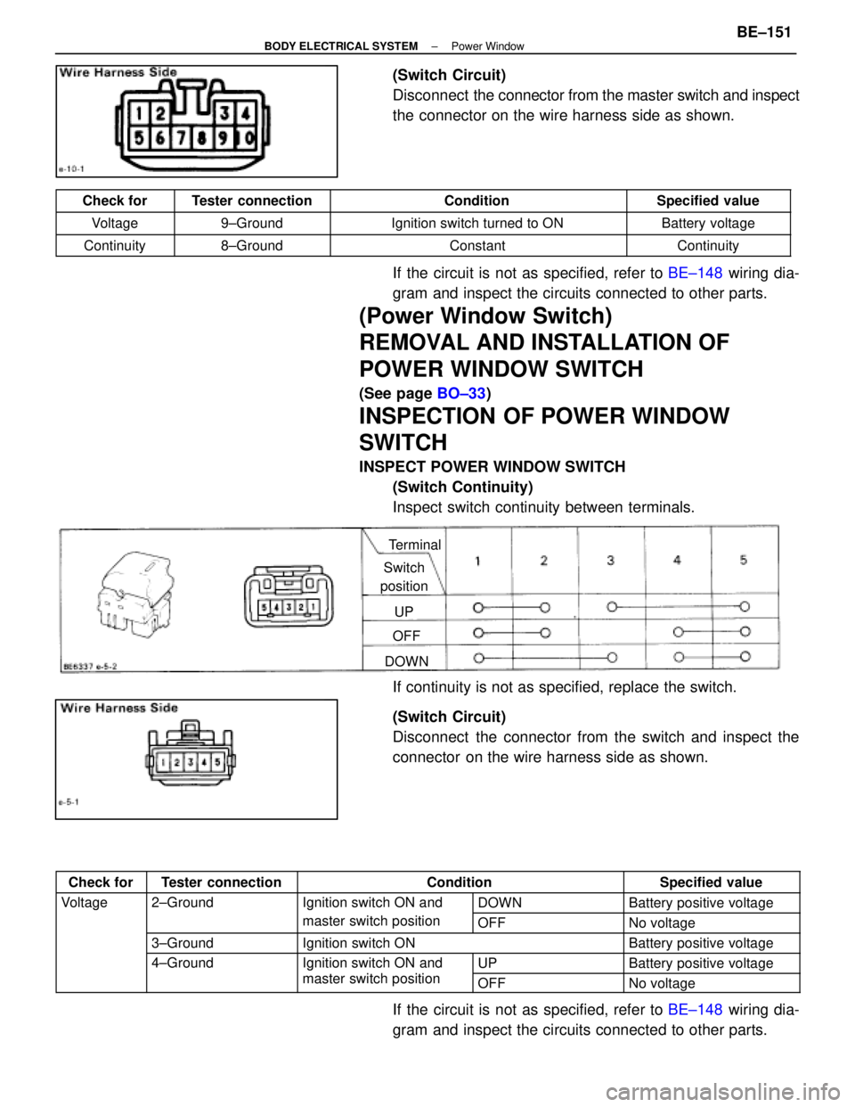
(Switch Circuit)
Disconnect the connector from the master switch and inspect
the connector on the wire harness side as shown.
Check forTester connectionConditionSpecified value
Voltage9±GroundIgnition switch turned to ONBattery voltage
Continuity8±GroundConstantContinuity
If the circuit is not as specified, refer to BE±148 wiring dia-
gram and inspect the circuits connected to other parts.
(Power Window Switch)
REMOVAL AND INSTALLATION OF
POWER WINDOW SWITCH
(See page BO±33)
INSPECTION OF POWER WINDOW
SWITCH
INSPECT POWER WINDOW SWITCH
(Switch Continuity)
Inspect switch continuity between terminals.
Terminal
Switch
position
UP
OFF
DOWN
If continuity is not as specified, replace the switch.
(Switch Circuit)
Disconnect the connector from the switch and inspect the
connector on the wire harness side as shown.
Check forTester connectionConditionSpecified value
Voltage2±GroundIgnition switch ON andDOWNBattery positive voltagegg
master switch positionOFFNo voltage
3±GroundIgnition switch ONBattery positive voltage
4±GroundIgnition switch ON and UPBattery positive voltageg
master switch positionOFFNo voltage
If the circuit is not as specified, refer to BE±148 wiring dia-
gram and inspect the circuits connected to other parts.
±
BODY ELECTRICAL SYSTEM Power WindowBE±151
WhereEverybodyKnowsYourName
Page 547 of 4087

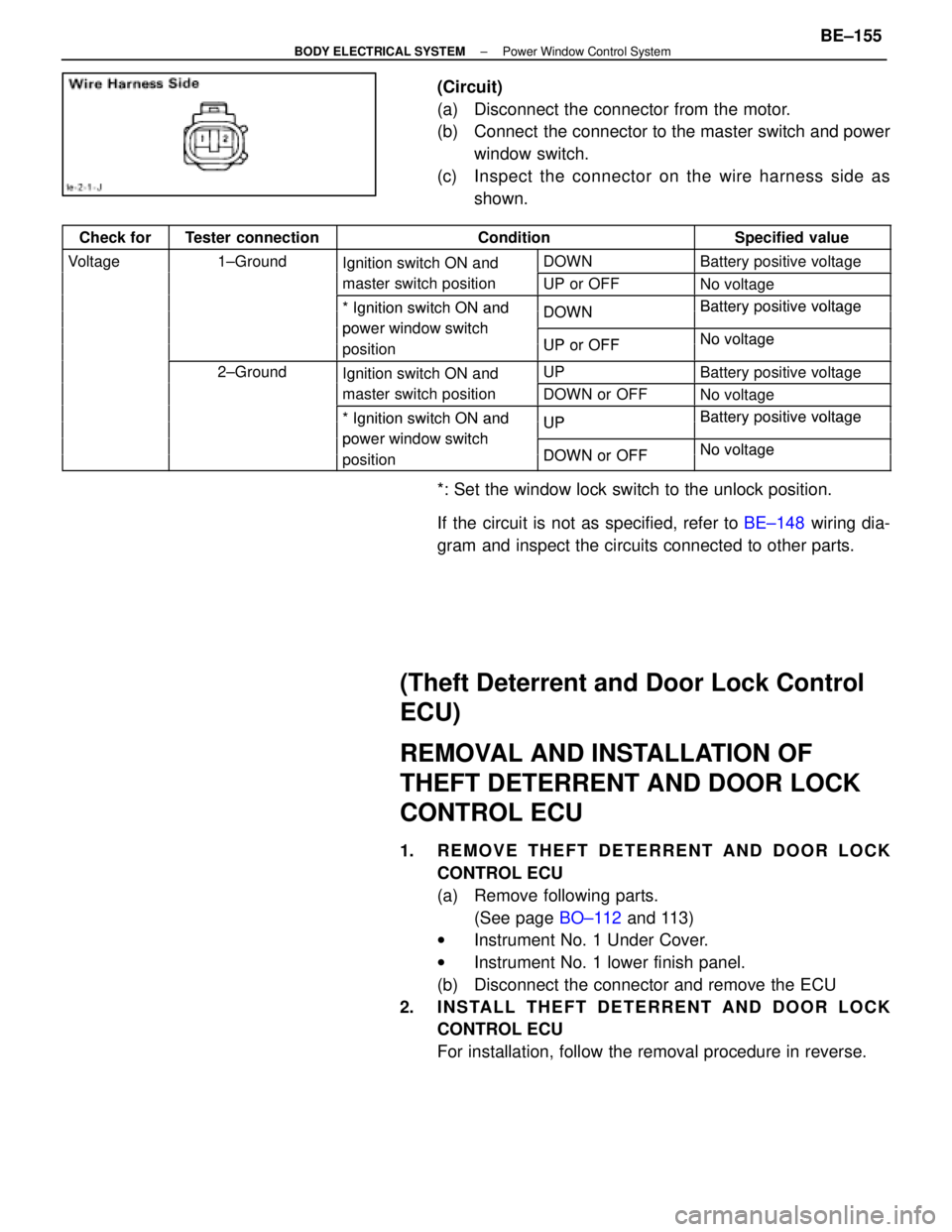
(Circuit)
(a) Disconnect the connector from the motor.
(b) Connect the connector to the master switch and powerwindow switch.
(c) Inspect the c onnector on the wire harness side as
shown.
Check forTester connectionConditionSpecified value
Voltage1±GroundIgnition switch ON andDOWNBattery positive voltagegIgnition switch ON and
master switch positionUP or OFFNo voltage
*Ignition switch ON andDOWNBatterypositive voltage* Ignition switch ON and
power window switch
DOWNBattery ositive voltage
power window switch
iti
UP or OFFNo voltagepositionUP or OFFNo voltage
2±GroundIgnition switch ON andUPBattery positive voltageIgnition switch ON and
master switch positionDOWN or OFFNo voltage
*Ignition switch ON andUPBatterypositive voltage* Ignition switch ON and
power window switch
UPBattery ositive voltage
power window switch
iti
DOWN or OFFNo voltagepositionDOWN or OFFNo voltage
*: Set the window lock switch to the unlock position.
If the circuit is not as specified, refer to BE±148 wiring dia-
gram and inspect the circuits connected to other parts.
(Theft Deterrent and Door Lock Control
ECU)
REMOVAL AND INSTALLATION OF
THEFT DETERRENT AND DOOR LOCK
CONTROL ECU
1. REMOVE THEFT DETERRENT AND DOOR LOCK CONTROL ECU
(a) Remove following parts.(See page BO±112 and 113)
w Instrument No. 1 Under Cover.
w Instrument No. 1 lower finish panel.
(b) Disconnect the connector and remove the ECU
2. INSTALL THEFT DETERRENT AND DOOR LOCK CONTROL ECU
For installation, follow the removal procedure in reverse.
±
BODY ELECTRICAL SYSTEM Power Window Control SystemBE±155
WhereEverybodyKnowsYourName
Page 551 of 4087
Wiring and Connector Diagrams
Parts Inspection
(Liquid Crystal Inner Mirror)
REMOVAL AND INSTALLATION OF
LIQUID CRYSTAL INNER MIRROR
(See page BO±44)
INSPECTION OF LIQUID CRYSTAL
INNER MIRROR
INSPECT LIQUID CRYSTAL INNER MIRROR
(a) Using a screw driver, pry out the cover.
(b) Remove two screws and center visor.
(Operation)
(a) Connect the positive (+) lead from the battery to terminal
1 and the negative (±) lead to terminal 2.
±
BODY ELECTRICAL SYSTEM Liquid Crystal Inner Mirror SystemBE±165
WhereEverybodyKnowsYourName
Page 552 of 4087

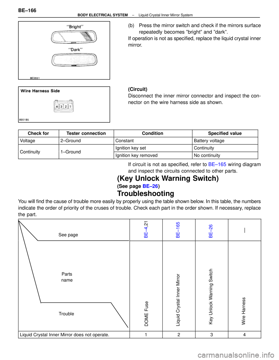
(b) Press the mirror switch and check if the mirrors surfacerepeatedly becomes ºbrightº and ºdarkº.
If operation is not as specified, replace the liquid crystal inner
mirror.
(Circuit)
Disconnect the inner mirror connector and inspect the con-
nector on the wire harness side as shown.
Check forTester connectionConditionSpecified value
Voltage2±GroundConstantBattery voltage
Continuity1 GroundIgnition key setContinuityContinuity1±GroundIgnition key removedNo continuity
If circuit is not as specified, refer to BE±165 wiring diagram
and inspect the circuits connected to other parts.
(Key Unlock Warning Switch)
(See page BE±26)
Troubleshooting
You will find the cause of trouble more easily by properly using the table \
shown below. In this table, the numbers
indicate the order of priority of the cruses of trouble. Check each part in the \
order shown. If necessary, replace
the part.
See pageBE±4,21BE±165BE±26 ±±
TroubleParts
name
DOME FuseLiquid Crystal Inner MirrorKey Unlock Warning SwitchWire Harness
Liquid Crystal Inner Mirror does not operate.1234
BE±166±
BODY ELECTRICAL SYSTEM Liquid Crystal Inner Mirror System
WhereEverybodyKnowsYourName